Dell UPS 10000R: instruction
Class: Computer Hardware
Type:
Manual for Dell UPS 10000R
Table of contents
- Notes and Warnings
- System Features
- Finding Information What are You Looking For? Find It Here
- Installation and Startup
- Unpacking the Cabinet To unpack the system: Using a forklift or pallet jack, move the shipping carton and pallet near the rack where you will install the UPS. Detach and remove the outer carton.
- Remove the two accessory boxes tucked into the channels in the top Styrofoam section. Open the accessory boxes and set them on a flat, stable surface nearby. Remove the top Styrofoam section and set it on a flat, stable surface nearby.
- Remove both retaining brackets from the UPS: Ensure all battery connectors are disconnected.
- Remove the battery trays from the UPS:
- With one person on each side, carefully lift the cabinet out of the styrofoam using the handles on the cardboard. Place the cabinet on a flat, stable surface in a protected area near the rack where you will install it.
- Rackmount Setup To install the UPS in a rack:
- Installing the Rails Remove the rails from the rail kit accessory box. Select the proper holes in the rail for positioning the cabinet in the desired location in the rack. Locate the rails at the bottom of the 5U space allocated for the UPS. Position the left and right rails as illustrated. Attach the the left and right rails to the rack:
- Installing and Securing the Cabinet Slide the cabinet onto the rails and into the rack. Secure the front of the cabinet to the rack using the four thumbscrews on the mounting brackets. Tighten the thumbscrews clockwise by hand; do not use power tools. Installing the Battery Trays Locate the battery trays you placed near the rack.
- Install the battery trays: Tuck the loop tabs into the plastic sleeve on the front of each battery tray to move them out of the way. Connecting Internal Battery Connectors Connect the internal battery connectors:
- Replacing the Battery Retaining Brackets Replace the left (L)and right (R) battery retaining brackets: Installing the UPS Front Cover
- Install the UPS front cover:
- Connecting the Equipment To install the UPS:
- Hardwiring the UPS Input
- Removing the Terminal Block Cover
- Manufacturer Type Rating
- Installing the Input and Ground Wires
- Starting the UPS To start up the UPS: Verify that the internal batteries are connected.
- Charge the batteries.
- Identifying the UPS Rear Panels 10 kW 208V UPS (DELL10KWOLHVUS)
- 10 kW 230V UPS (DELL10KWOLHV)
- 10 kW 230V UPS (DELL10KWOLHVB)

Dellt Online Rack UPS
10 kW
Getting Started With
Your System
Démarrer Avec Votre Système
Erste Schritte mit Ihrem System
Начало работы c системой
Cómo empezar con su sistema
系统使用 入门指南
系統使用 入門指南
사용자의 시스템 시작하기
はじめに システムについて
DELL10KWOLHVUS, DELL10KWOLHV, DELL10KWOLHVB
DELL10KWEBM
www.dell.com | www.support.dell.com | www.dellups.com


Dellt Online Rack UPS
10 kW
Getting Started
With Your System
DELL10KWOLHVUS, DELL10KWOLHV, DELL10KWOLHVB
DELL10KWEBM
www.dell.com | www.support.dell.com | www.dellups.com

Notes and Warnings
NOTE:
A NOTE indicates important information that helps you make better use of your software.
DANGER:
A DANGER indicates an imminently hazardous situation which, if not avoided, will result in death or
serious injury.
WARNING:
A WARNING indicates a potentially hazardous situation which, if not avoided, could result in death or
injury.
CAUTION:
A CAUTION indicates a potentially hazardous situation which, if not avoided, may result in minor or
moderate injury or in property damage incidents.
DANGER:
Observe the following instruction to help prevent an imminently hazardous situation which, if not
avoided, will result in death or serious injury:
S
The U PS contains LETHAL VOLTAGES. All repairs and service should be performed by
AUTHORIZED SERVICE PERSONNEL ONLY.ThereareNO USER SERVICEABLE PARTS
inside the UPS or EBM.
Information in this document is subject to change without notice.
E 2012 Dell Inc. All rights reserved.
Reproduction in any manner whatsoever without the written permission of Dell Inc. is strictly forbidden.
Trademarks used in this text: Dell and the DELL logo are trademarks of Dell Inc.; ENERGY STAR name is a registered trademark owned
by the U.S. Environmental Protection Agency.
Other trademarks and trade names may be used in this document to refer to either the entities claiming the marks and names or their
products. Dell Inc. disclaims any proprietary interest in trademarks and trade names other than its own.
December 2012

System Features
Providing outstanding performance and reliability, the UPS's unique benefits include:
S
Online UPS design with pure sine wave output.
S
True online double-conversion technology with high power density, utility frequency
independence, a nd generator compatibility.
S
Buck and Boost voltage regulation that ensures regulated voltage to your load by correcting voltage
fluctuations.
S
The UPS filters and regulates incoming AC power and provides consistent power to your
equipment without draining the battery.
S
Selectable High Efficiency mode of operation.
S
5U UPS height.
S
Start-on-battery capability for powering up the UPS even if utility power is not available.
S
Maintenance is simplified by allowing the safe replacement of batteries without powering down the
UPS.
S
Dell service tag information can be read from the front panel LCD display.
S
Extended runtime with an optional Extended Battery Module (EBM).
S
Emergency shutdown control through the Remote Emergency Power-off (REPO) ports.
S
Two standard communication ports (USB and RS-232 serial port).
S
Optional Dell Network Management Card (also known as the NMC) with enhanced
communication capabilities for increased power protection and control.
S
Optional Environmental Monitoring Probe (EMP) for collecting temperature and humidity
readings in the frame environment and monitoring the environmental data remotely. You can also
collect and retrieve the status of two user-provided contact devices.
S
Advanced power management with the Dellt Multi-UPS Management Console (MUMC) and
Dellt UPS Local Node Manager (ULNM) Web-based software applications for graceful
shutdowns and power monitoring.
S
Sequential shutdown and load management through separate receptacle groups called load
segments.
S
Firmware that is easily upgradable without a service call.
S
Backed by worldwide agency approvals.
®
S
ENERGY STAR
certified UPSs.
System Features
|
3

Finding Information
CAUTION:
The Safety, Environmental, and Regulatory Information document provides important safety and
regulatory information.
What are You Looking For?
Find It Here
S The user's guide for my UPS
Dell UPS Disc
S The user's guide for the Dell Network Management
Card
S Dell MUMC and Dell ULNM User's Guides
NOTE:
Documentation and software updates can be
found at www.support.dell.com and at
www.dellups.com.
S Specifications
Dell UPS User's Guide
S How to configure UPS settings
The user's guide is available on the Dell UPS disc and
S How to troubleshoot and solve problems
on www.support.dell.com.
S How to install REPO control
S Safety instructions
Safety, Environmental, and Regulatory Information
S Regulatory information
S Recycling information
S Warranty information
Dell Warranty and Support Information
S Terms and Conditions (U.S. only)
S End User License Agreement
S Support information Dell Support Website — www.support.dell.com
NOTE:
Select your region or business segment to view
the appropriate support site.
4
|
Finding Information
Installation and Startup
CAUTION:
Before performing the procedures in this document, read and follow the safety instructions and
important regulatory information in your Safety, Environmental, and Regulatory Information document.
CAUTION:
Unpacking the cabinet in a low-temperature environment may cause condensation to occur in and
on the cabinet. Do not install the cabinet until the inside and outside of the cabinet are absolutely dry (hazard
of electric shock).
CAUTION:
Installing or removing the battery trays should be performed or supervised by personnel
knowledgeable about batteries and the required precautions. Keep unauthorized personnel away from
batteries.
Installation and Startup
|
5
CAUTION:
The cabinet is heavy (99 kg/218 lb): Always remove both battery trays from the UPS before lifting
the cabinet. Lifting the cabinet into the rack requires a minimum of two people.
CAUTION:
The batteries are heavy (32 kg/71 lb). Use proper lifting techniques when removing the batteries.
NOTE:
Use care when moving and opening the carton. Leave the components packaged until ready to install.
This section describes the steps to set up your system for the first time.
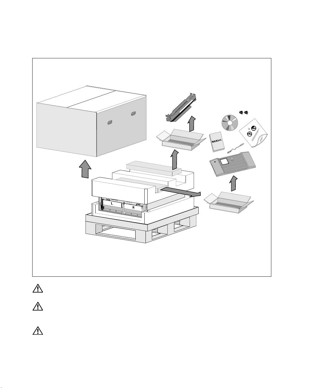
Unpacking the Cabinet
To unpack the system:
1
Using a forklift or pallet jack, move the shipping carton and pallet near the rack where you will
install the UPS.
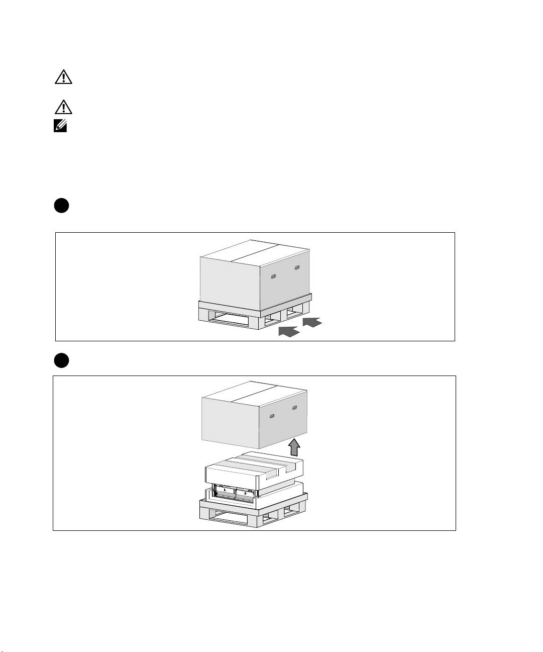
2
Detach and remove the outer carton.
6
|
Installation and Startup

3
Remove the two accessory boxes tucked into the channels in the top Styrofoam section.
4
Open the accessory boxes and set them on a flat, stable surface nearby.
NOTE:
The Dell Online Rack UPS 10 kW User's Guide provides unpacking and installation procedures. To refer
to it, remove it from the accessory box before you set the accessory boxes aside.
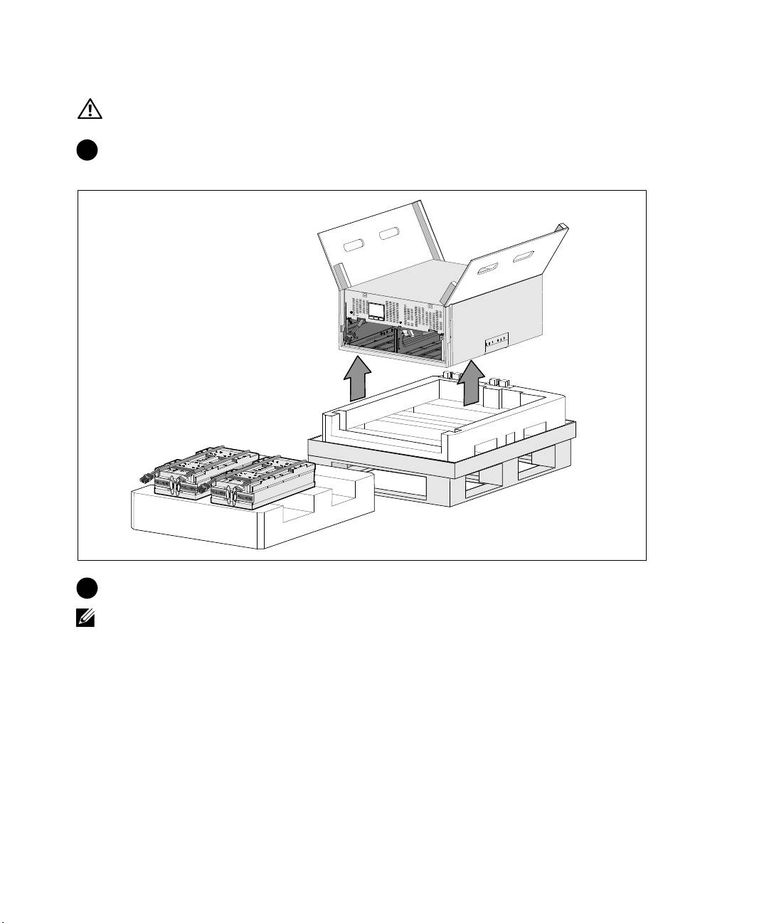
5
Remove the top Styrofoam section and set it on a flat, stable surface nearby.
Installation and Startup
|
7
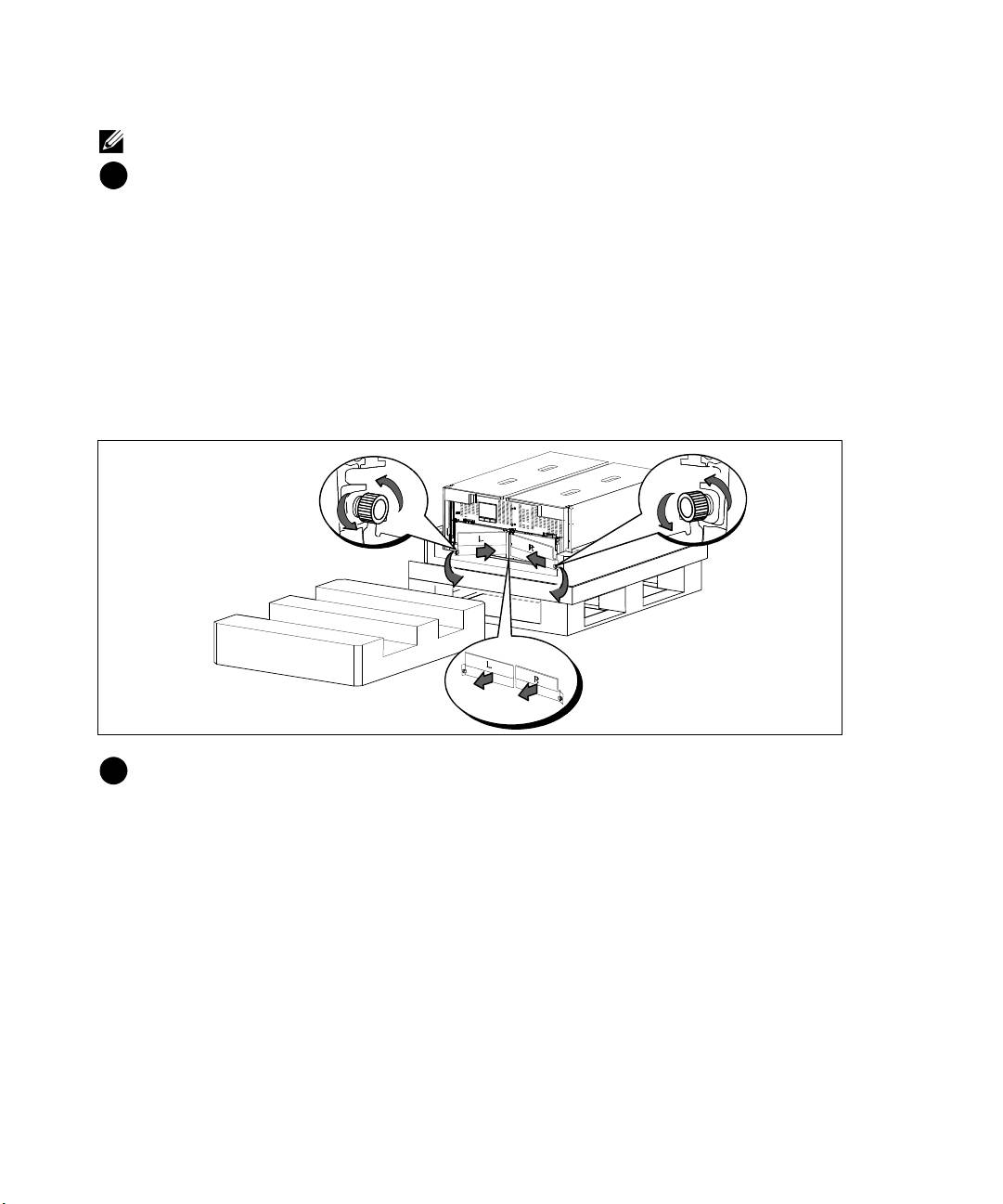
NOTE:
The battery retaining brackets are labeled L (Left) and R (Right) to indicate where they must be installed.
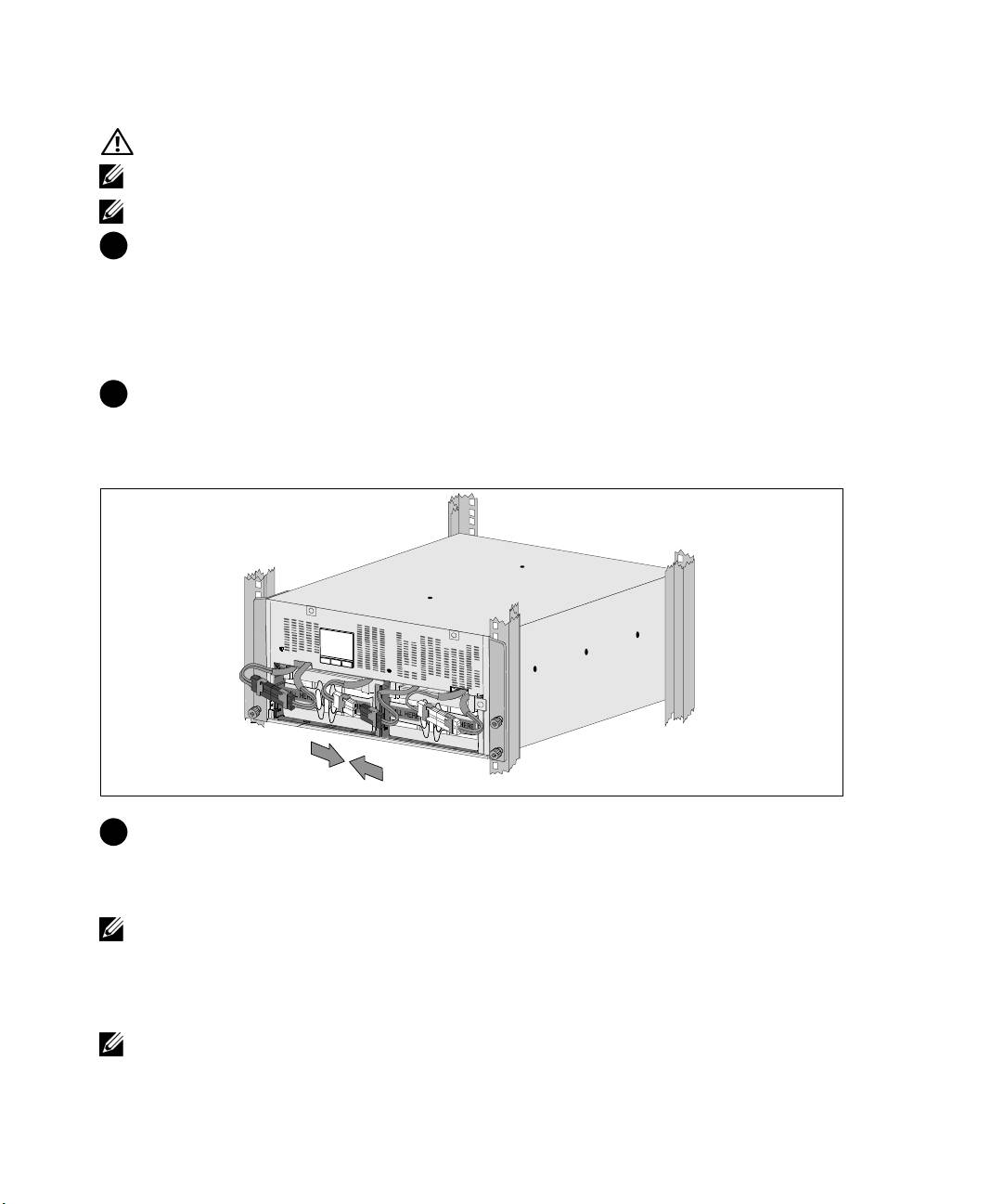
6
Remove both retaining brackets from the UPS:
Locate the left (labeled L) retaining bracket. On the left side of the chassis, turn the thumbscrew
counter-clockwise to release the left retaining bracket.
Push the bracket toward the center post to disengage it from the chassis. Swing the bracket toward
you and pull the bracket to the left to remove it. Set the bracket aside.
Locate the right (labeled R) retaining bracket. On the right side of the chassis, turn the
thumbscrew counter-clockwise to release the right retaining bracket.
Push the bracket toward the center post to disengage it from the chassis. Swing the bracket toward
you and pull the bracket to the right to remove it. Set the bracket aside.
7
Ensure all battery connectors are disconnected.
8
|
Installation and Startup
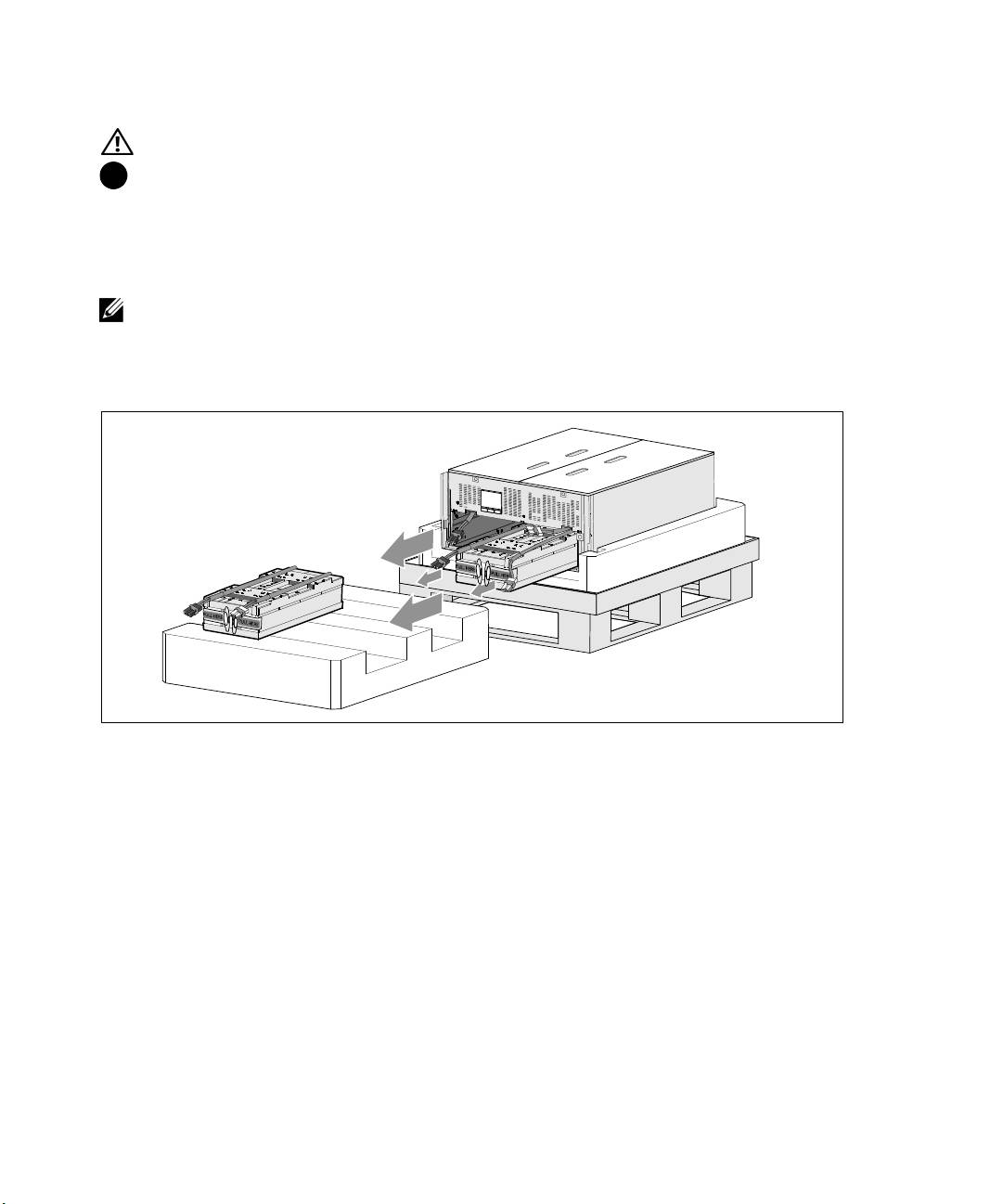
CAUTION:
The batteries are heavy (32 kg/71 lb). Use proper lifting techniques when removing the batteries.
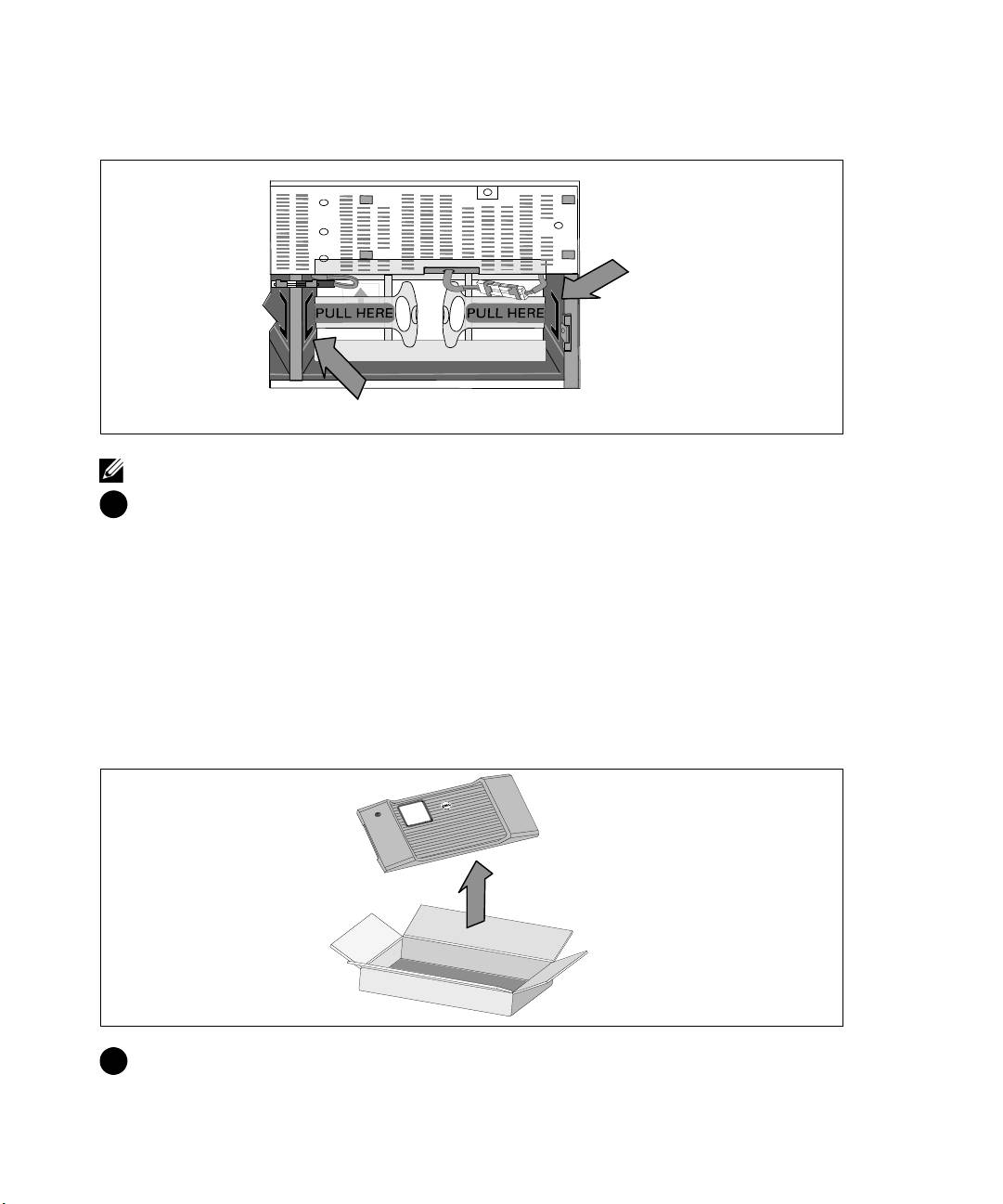
8
Remove the battery trays from the UPS:
Move the disconnected UPS battery connectors at the top of the battery compartment out of the
way.
Grip the two plastic loop tabs on the front of the battery tray. Pull the tray toward you to remove.
NOTE:
The orange PULL HERE labels indicate where to grasp the loop tabs.
Set the battery tray on the Styrofoam section you removed from the top of the UPS.
Repeat with the second battery tray.
Installation and Startup
|
9
CAUTION:
The cabinet is heavy (46 kg/101 lb) with the batteries removed. Lifting the cabinet from the
shipping carton requires a minimum of two people.
9
With one person on each side, carefully lift the cabinet out of the styrofoam using the handles on
the cardboard.
10
Place the cabinet on a flat, stable surface in a protected area near the rack where you will install it.
NOTE:
Ensure that the area has adequate airflow and is free of humidity, flammable gas, and corrosion.
10
|
Installation and Startup
Rackmount Setup
CAUTION:
The cabinet is heavy (99 kg/218 lb). Always remove both battery trays from the UPS before lifting
the cabinet and installing the UPS on the rails in the rack. Lifting the cabinets into the rack requires a
minimum of two people.
CAUTION:
Installing or removing the batteries should be performed or supervised by personnel
knowledgeable about batteries and the required precautions. Keep unauthorized personnel away from
batteries.
CAUTION:
The batteries are heavy (32 kg/71 lb). Use proper lifting techniques when removing the batteries.
CAUTION:
If installing an optional EBM, the EBM must be located below the UPS with no U space between
the UPS and EBM. This provides better weight distribution in the rack, easier access to the UPS control panel,
and easier routing for the battery cable connections. This also prevents strain between the EBM cord and the
UPS connection and possible connection failure.
WARNING:
For Rack-Mounted Systems: When installing multiple systems in a rack, complete all of the
procedures for the current system before attempting to install the next system.
NOTE:
Mounting rails are required for each individual cabinet.
NOTE:
The cabinet is shipped without the front cover bezel attached.
NOTE:
The following instructions are the same for square-hole racks and unthreaded, round-hole racks. The
rails fit both rack styles.
To install the UPS in a rack:
1
Ensure that the following are placed on a flat, stable surface near the rack where you will install
the UPS:
S
cabinet
S
two UPS accessory boxes
S
two battery trays (UPS only)
S
two battery retaining brackets (UPS only)
Installation and Startup
|
11
Installing the Rails
2
Remove the rails from the rail kit accessory box.
3
Select the proper holes in the rail for positioning the cabinet in the desired location in the rack.
Locate the rails at the bottom of the 5U space allocated for the UPS.
CAUTION:
If installing an optional EBM, make provision for installing the EBM directly below the UPS with
no U space between the UPS and EBM.
NOTE:
Observe the labels on the rails for right front (labeled RIGHT FRONT) and left front (labeled LEFT
FRONT). This is the way the rails should be positioned for installation.
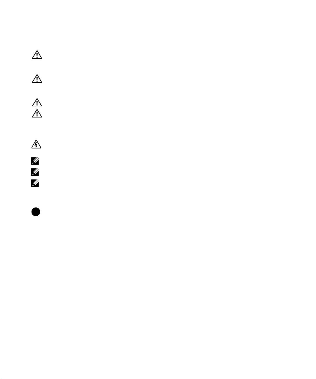
4
Position the left and right rails as illustrated. Attach the the left and right rails to the rack:
Engage the back end of the rail until it fully seats on the vertical rack flange and the hook latch
locks i n place.
Pulltherailjustpastthefrontoftherack.
Push the front end of the rail until it fully seats on the vertical rack flange and the hook latch locks
in place.
12
|
Installation and Startup
Installing and Securing the Cabinet
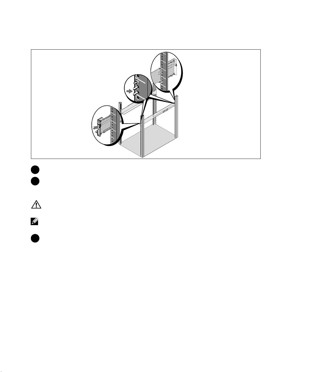
CAUTION:
The cabinet is heavy (46 kg/101 lb) with the batteries removed. Lifting the cabinet into the rack
requires a minimum of two people.
5
Slide the cabinet onto the rails and into the rack.
6
Secure the front of the cabinet to the rack using the four thumbscrews on the mounting brackets.
Tighten the thumbscrews clockwise by hand; do not use power tools.
Installing the Battery Trays
7
Locate the battery trays you placed near the rack.
Installation and Startup
|
13
CAUTION:
The batteries are heavy (32 kg/71 lb). Use proper lifting techniques when installing the batteries.
NOTE:
The battery trays can be installed in either battery compartment.
NOTE:
Insert the tray with the caution label arrow pointing upward.
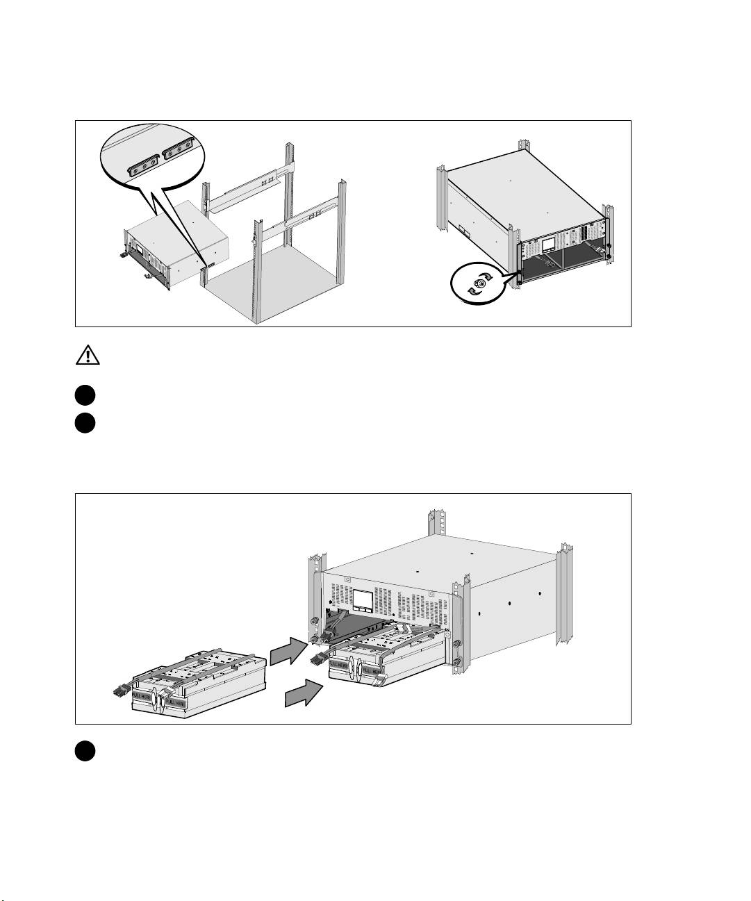
8
Install the battery trays:
Move the UPS battery connectors at the top of the battery compartment out of the way.
Slide the battery tray into the battery compartment completely.
Repeat to install the second battery tray.
9
Tuck the loop tabs into the plastic sleeve on the front of each battery tray to move them out of the
way.
Connecting Internal Battery Connectors
10
Connect the internal battery connectors:
Connect the far-left battery tray connector to the f ixed UPS connector. Connect the far-right
battery tray connector to the fixed UPS connector.
NOTE:
A small amount of arcing may occur when connecting the batteries. This is normal and does not
damage the unit or present any safety concern.
Locate and connect the battery jumpers located on either side of the center post. Place the
connectors on the small shelf at the top of the center post.
NOTE:
Connecting the center battery jumpers connects the two battery trays serially.
14
|
Installation and Startup
Replacing the Battery Retaining Brackets
Chassis Side Channel
Center Post Side Channel
NOTE:
The battery retaining brackets are labeled L (Left) and R (Right) to indicate where they must be installed.
11
Replace the left (L)and right (R) battery retaining brackets:
For the first battery retaining bracket, insert the bracket tab into the channel on the side of the
center post. Fit the connected battery cables snugly behind the retaining bracket.
Align the end of the battery retaining bracket wi th the channel on the side of the chassis. Push the
bracket until it is firmly seated into the side channel.
Turn the thumbscrew clockwise to secure the bracket.
Repeat to replace the second battery retaining bracket.
Installing the UPS Front Cover
12
Remove the front cover f rom the accessory box.
Installation and Startup
|
15
NOTE:
Keep the software CD, communication cable, and (if needed) REPO connectors in the accessory box
until you install the UPS.
1
2
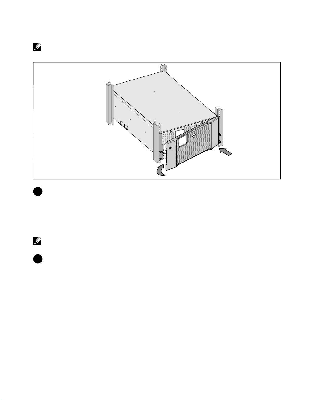
13
Install the UPS front cover:
Align the front cover with the front of the chassis.
Insert the right-side tabs on the front cover into tab openings on the right-side chassis.
Push the left side of the cover forward and snap it to the chassis.
NOTE:
Ensure that the LCD panel on the UPS chassis aligns with the LCD window on the front cover before
securing the cover to the chassis.
14
Discard or recycle the packaging in a responsible manner, or store it for future use.
16
|
Installation and Startup

Connecting the Equipment
To install the UPS:
1
If you plan to use Dell MUMC and Dell ULNM software, establish communication in one of the
following ways:
S
using the Dell Network Management Card (if installed)
S
using the supplied cable to connect your computer to the USB port
NOTE:
For more information about communication options, refer to the Dell Online Rack UPS 10 kW User's
Guide.
2
If your rack has conductors for grounding or bonding of ungrounded metal parts, connect the
ground cable (not supplied) to the ground bonding screw. See “UPS Rear Panels” on page 24 for
the l ocation of the ground bonding screw for each of the three models.
3
If an emergency power-off (disconnect) switch isrequiredbylocalcodes, refer to “Installing
Remote Emergency Power-off” in the Dell Online Rack UPS 10 kW User's Guide.
4
If you are installing an optional EBM, refer to the Dell Online Rack EBM 10 kW Getting Started
Guide for installation instructions.
CAUTION:
If the UPS is stored or used without an EBM, the battery connector cover on the rear panel of the
UPS must be installed as a safety precaution.
5
Plug the equipment to be protected into the UPS output receptacles, but do not turn on the
protected equipment.
6
Make any necessary provisions for cord retention and strain relief.
NOTE:
Verify that the total equipment ratings do not exceed the UPS capacity to prevent an overload alarm.
Installation and Startup
|
17
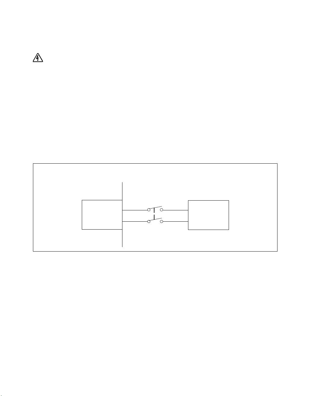
Hardwiring the UPS Input
WARNING:
Risk of electrical shock. Only qualified service personnel (such as a licensed electrician) shall
perform the electrical installation.
The Dell Online Rack hardwired models require a dedicated branch circuit that meets the following
requirements:
S
Protection device requires a two-pole disconnection device between the UPS input and the mains
S
Breaker must be wall-mounted and be readily accessible to the operator
S
For Europe. Breaker must meet the IEC/EN 60934 standard and at least 3 mm contact air gap
S
200–240 Vac
S
Single-phase
S
50/60 Hz
S
Flexible metal conduit (recommended for ease of service and maintenance)
Wall
2-pole
Breaker
Line
AC Mains
UPS
Neutral/L2
18
|
Installation and Startup
