Dell PowerEdge C8000: instruction
Class: Computer Hardware
Type:
Manual for Dell PowerEdge C8000
Table of contents
- Notes, Cautions, and Warnings
- CAUTION: Restricted Access Location Installation and Configuration Recommended Tools Unpacking the System
- Installing the Tool-Less Rail Solution Determine where to place the rails in the rack. Make sure there is enough space in the rack for the 4U chassis. In a standard rack, the height of a 4U chassis will span 12 rack post holes. Use the marking indicated on the left and right sides of the rail to orient the rail correctly to the rack posts. Attach the left rail and stopping bracket to the rack. a
- e f g
- h i
- 4 Attach the right rail and stopping bracket to the rack. Installing the System Emptying the System
- • To remove a • To remove a
- • To remove a power sled, pull up on the release latch • To remove a double-wide sled blank, squeeze and hold the release latches
- • To remove a single-wide sled blank, pull up on the release latch
- Install the System Into the Rack 1
- 2
- Sled Bay Numbering Sled Bays Sled module type
- Populating the System
- Install the External PDU Into the Rack 1 2
- 3 4
- 5 a
- d e
- 6
- Rack Configuration
- Connecting the Keyboard, Mouse, and Monitor
- Connecting the Power Cables Server Enclosure with Internal Power Source
- Server Enclosure with External Power Source
- Connecting the Server Enclosure to a Rack PDU To connect a single server enclosure to the PDU:
- To connect multiple server enclosures to the PDU:
- Close the cable cover and secure to the PDU.
- Connecting the PDU to the Network 1 a b
- c
- Powering Up the Systems Turning on the PDU 1 a b 2
- 3 4 Turning On the Server Enclosure
- Turning On the Sleds
- Complete the Operating System Setup Supported Operating Systems
- Other Information You May Need
- NOM Information PowerEdge C8000 PowerEdge C8220
- PowerEdge C8220X PowerEdge C8000XD
- Technical Specifications Compute Sled Specifications (Per Sled) System chipset Memory Storage device
- Compute Sled Specifications (Per Sled)(continued) Graphics card Expansion slots Interfaces Power
- Storage Sled Specifications (Per Sled) Storage device Interface Power Sled Specifications (Per Sled) Interfaces Power supply module (per power supply)
- Server Enclosure Specifications Physical Sled Support Interfaces System fans Power
- Environmental
- Environmental(continued)
Dell PowerEdge
C8000, C8220, C8220X,
and C8000XD
Getting Started
With Your System
Začínáme se systémem
Mise en route de votre système
Erste Schritte mit dem System
Τα πρώτα βήματα με το σύστημά σας
Rozpoczęcie pracy z systemem
Начало работы с системой
Introducción al sistema
Sisteminizi Kullanmaya Başlarken
FILE LOCATION: J:\DL\DL133449\DTP\NJK8Nfc4.fm
Regulatory Model: B10S, B05B, and B06B
Regulatory Type: B10S001, B05B001,
B06B001, and B06B002

FILE LOCATION: J:\DL\DL133449\DTP\NJK8Nfc4.fm

Dell PowerEdge
C8000, C8220, C8220X,
and C8000XD
Getting Started
With Your System
FILE LOCATION: J:\DL\DL133449\DTP\NJK8Netp4.fm
Regulatory Model: B10S, B05B, and B06B
Regulatory Type: B10S001, B05B001,
B06B001, and B06B002
FILE LOCATION: J:\DL\DL133449\DTP\NJK8Netp4.fm
Notes, Cautions, and Warnings
NOTE:
A NOTE indicates important information that helps you make better use of
your computer.
CAUTION:
A CAUTION indicates potential damage to hardware or loss of data if
instructions are not followed.
WARNING:
A WARNING indicates a potential for property damage, personal
injury, or death.
____________________
Information in this publication is subject to change without notice.
© 2013 Dell Inc. All rights reserved.
Reproduction of these materials in any manner whatsoever without the written permission of Dell Inc.
is strictly forbidden.
Trademarks used in this text: Dell™, the DELL logo, Dell Precision™, OptiPlex™, Latitude™,
PowerEdge™, PowerVault™, PowerConnect™, OpenManage™, EqualLogic™, KACE™,
®
®
®
®
FlexAddress™ and Vostro™ are trademarks of Dell Inc. Intel
, Pentium
, Xeon
, Core™, Celeron
and Xeon Phi™ are registered trademarks of Intel Corporation in the U.S. and other countries.
®
®
®
®
®
Microsoft
, Windows
, Windows Server
, MS-DOS
and Windows Vista
are either trademarks or
®
registered trademarks of Microsoft Corporation in the United States and/or other countries. Red Hat
®
®
and Red Hat
Enterprise Linux
are registered trademarks of Red Hat, Inc. in the United States and/
®
or other countries. Novell
is a registered trademark and SUSE ™ is a trademark of Novell Inc. in
®
the United States and other countries. Oracle
is a registered trademark of Oracle Corporation and/
®
®
®
®
or its affiliates. Citrix
, Xen
, XenServer
and XenMotion
are either registered trademarks or
®
trademarks of Citrix Systems, Inc. in the United States and/or other countries. VMware
, Virtual
®
®
®
®
SMP
, vMotion
, vCenter
, and vSphere
are registered trademarks or trademarks of VMWare, Inc.
in the United States or other countries. NVIDIA and Tesla™ are trademarks and/or registered
trademarks of NVIDIA Corporation.Ubuntu is a registered trademark of Canonical Ltd.
Other trademarks and trade names may be used in this publication to refer to either the entities claiming
the marks and names or their products. Dell Inc. disclaims any proprietary interest in trademarks and
trade names other than its own.
Regulatory Model: B10S, B05B, and B06B
Regulatory Type: B10S001, B05B001, B06B001, and B06B002
2013 - 07 P/N NJK8N Rev. A04
CAUTION:
Restricted Access Location
This server is intended for installation only in restricted access locations as
defined where both these conditions apply:
• Access can only be gained by service persons or by users who have been
instructed about the reasons for the restrictions applied to the location
and about any precautions that shall be taken.
• Access is through the use of a tool or lock and key, or other means of
security, and is controlled by the authority responsible for the location.
Installation and Configuration
WARNING:
Before performing the following procedure, review and follow the
safety instructions that came with the system.
The PowerEdge C8000 server enclosure is a flexible and scalable 4U
rackmount chassis. PowerEdge C8000 features ten vertically aligned sled bays
that support a full sled or a mixed sled enclosure. A full sled enclosure can
include up to five C8220X double-wide compute sleds, ten C8220 single-wide
compute sleds, or five C8000XD storage sleds. A mixed sled enclosure can
support a mixture of differing sled types.
Recommended Tools
Before you begin the installation tasks, ensure that you have the following
items:
• #1 Phillips screwdriver
• #2 Phillips screwdriver
• Wrist grounding strap connected to ground
• Antistatic mat or antistatic foam
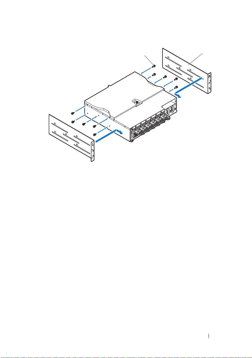
Unpacking the System
WARNING:
Whenever you need to lift the system, get others to assist you. To
avoid injury, do not attempt to lift the system by yourself.
CAUTION:
Wear a wrist grounding strap when handling system components.
1
Prepare an
antistatic mat or antistatic foam
to set the PowerEdge C8000
server enclosure on.
2
Unpack and place your enclosure on an
antistatic mat or antistatic foam
.
3
Save the cardboard containers for future use.
Template Last Updated - 2/7/2007 Getting Started With Your System
3
Installing the Tool-Less Rail Solution
WARNING:
Whenever you need to lift the system, get others to assist you. To
avoid injury, do not attempt to lift the system by yourself.
WARNING:
The system is not fixed to the rack or mounted on the rails. To avoid
personal injury or damage to the system, you must adequately support the system
during installation and removal.
WARNING:
To avoid a potential electrical shock hazard, a third wire safety
grounding conductor is necessary for the rack installation. The rack equipment
must provide sufficient airflow to the system to maintain proper cooling.
CAUTION:
The rail pegs must be flush with the rack posts to install
properly.
NOTE:
The rack rails are marked LEFT and RIGHT. The rail marked "LEFT" attaches
to the left rack posts and the rail marked "RIGHT" attaches to the right rack posts
when facing the front of the rack.
1
Determine where to place the rails in the rack. Make sure there is enough
space in the rack for the 4U chassis. In a standard rack, the height of a 4U
chassis will span 12 rack post holes.
2
Use the marking indicated on the left and right sides of the rail to orient
the rail correctly to the rack posts.
3
Attach the left rail and stopping bracket to the rack.
a
Position left rail marked "
LEFT
" to align with its mounting holes on the
rack posts.
b
Press and hold the rail release button
to open the latch on the front
end of the left rail.
c
Align the three pegs
with the mounting holes on the front rack post.
d
Release the button
when it engages to the front rack post.
NOTE:
Make sure the rail release button is engaged correctly.
NOTE:
The rails can be used in both square-hole and round-hole racks.
4
Getting Started With Your System
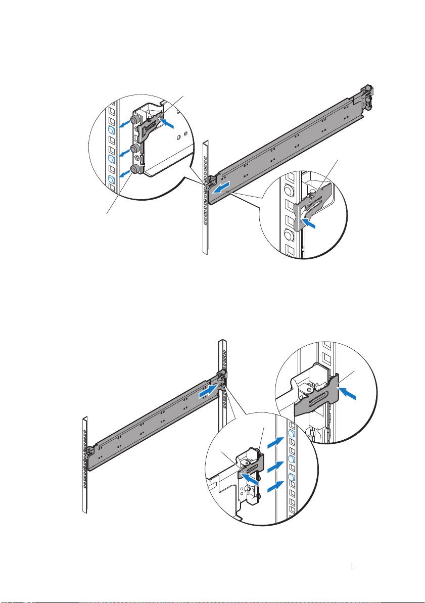
e
Press and hold the rail release button
to open the latch on the back
end of the rail.
f
Align the three pegs
with the mounting holes on the back rack post.
g
Release the button
when it engages to the back rack post.
Getting Started With Your System
5
1
3
2
3
2
1
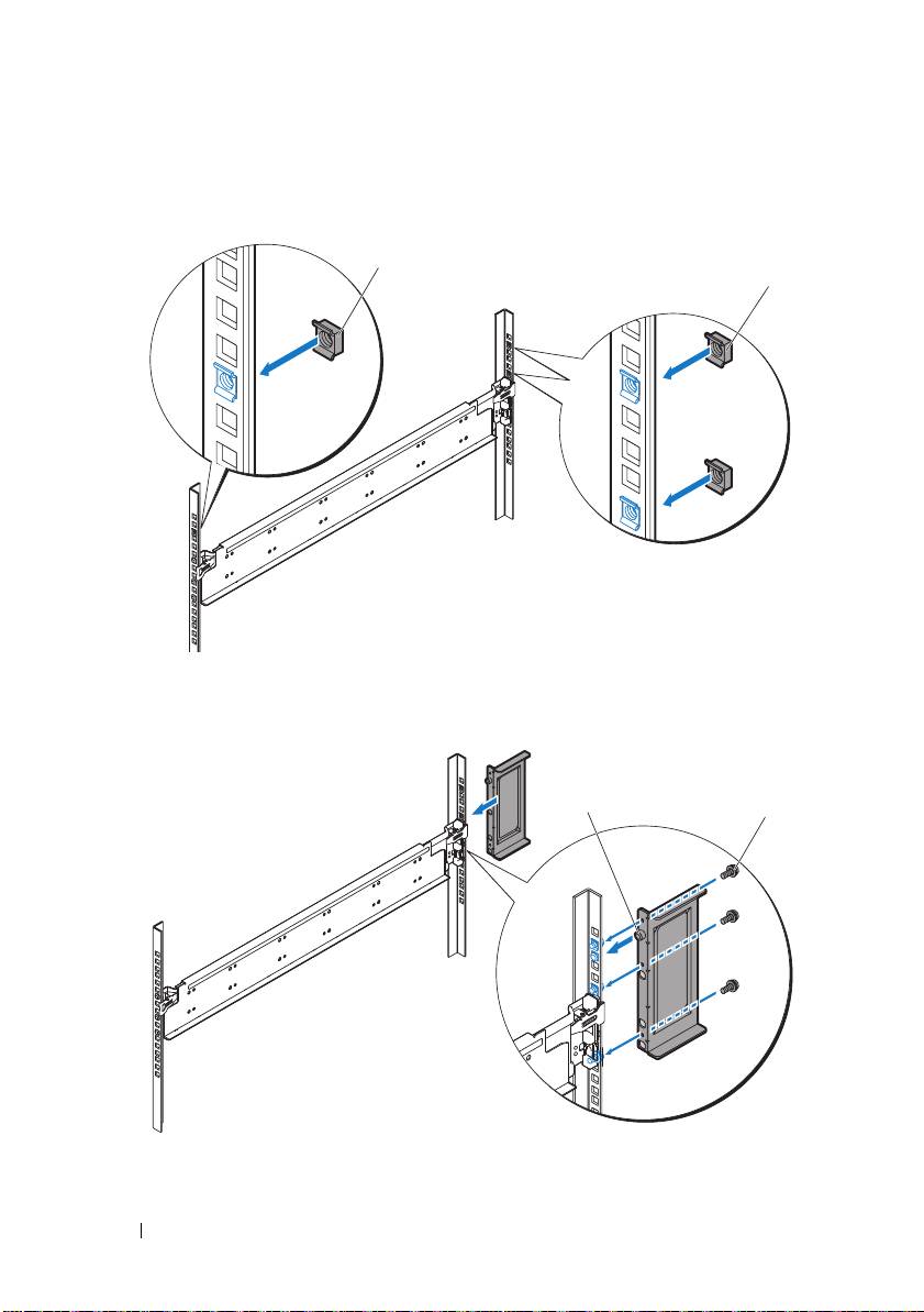
h
Install one cage nut
to the front rack post and two cage nuts
to
the back rack post.
i
Align the stopping bracket
to the back rack post and secure with the
three 10-32 screws
. Apply 35 in-lbs of torque to the screws.
6
Getting Started With Your System
1
2
1
2
4
Attach the right rail and stopping bracket to the rack.
Use the same procedure to install the right rail and stopping bracket to the
right rack posts.
NOTE:
To remove the rails, press and hold on the rail release button on the end
piece midpoint and unseat each rail.
Installing the System
This section includes the following subsections:
• Emptying the System
• Install the System Into the Rack
• Sled Bay Numbering
• Populating the System
• Install the External PDU Into the Rack
• Rack Configuration
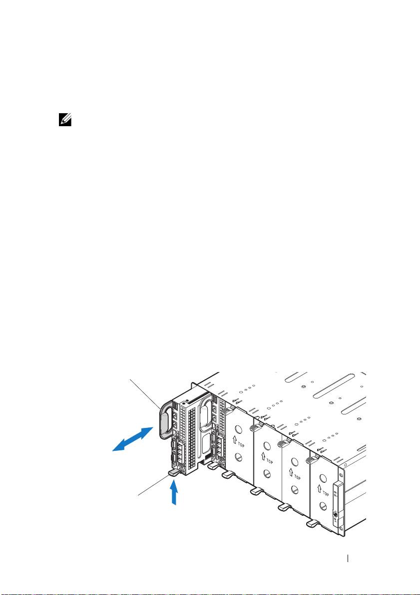
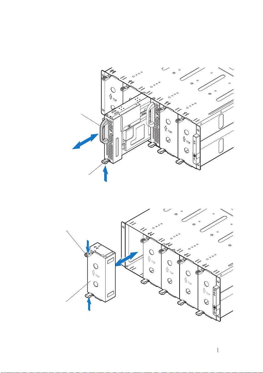
Emptying the System
Before you install a PowerEdge C8000 server enclosure into a rack, remove all
sled modules from the enclosure to reduce system weight and avoid injury.
Place all sled modules on an antistatic mat or antistatic foam.
• To remove a
C8220 single-wide compute sled, pull up on the
release latch
and using the handle
slide the sled out of the enclosure.
Getting Started With Your System
7
2
1
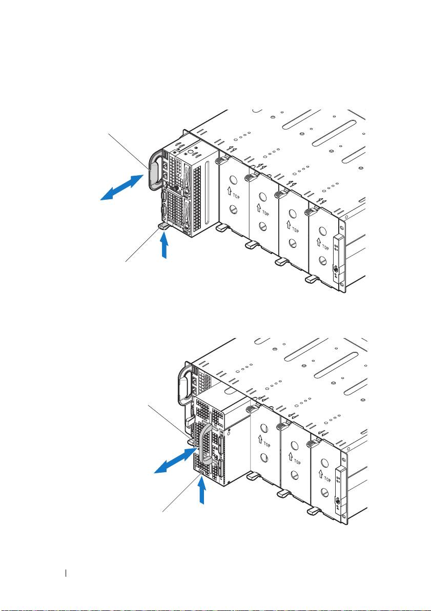
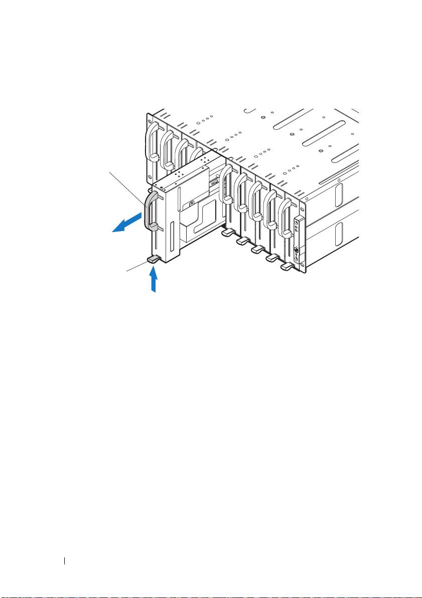
• To remove a
C8220X double-wide compute sled, pull up on the
release
latch
and using the handle
slide the sled out of the enclosure.
• To remove a
C8000XD storage sled, pull and hold the
release tab
and
using the handle
slide the sled out of the enclosure.
8
Getting Started With Your System
2
1
2
1
• To remove a power sled, pull up on the release latch
and using the
handle
slide the sled out of the enclosure.
• To remove a double-wide sled blank, squeeze and hold the release latches
and pull the sled blank out of the enclosure
.
Getting Started With Your System
9
2
1
1
2
• To remove a single-wide sled blank, pull up on the release latch
and
using the handle
slide the blank out of the enclosure.
10
Getting Started With Your System
2
1
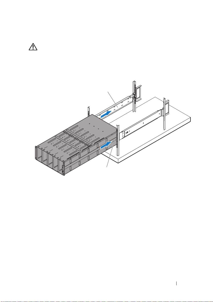
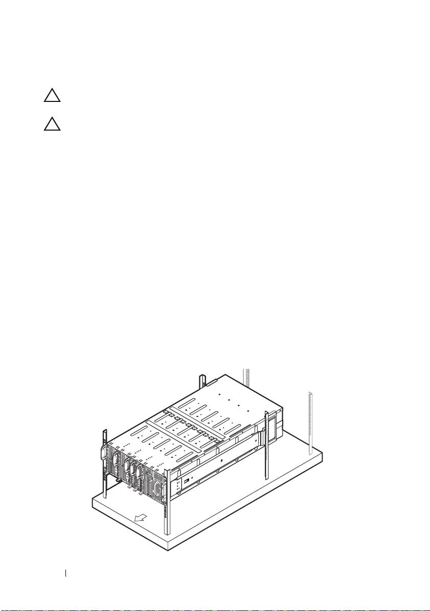
Install the System Into the Rack
WARNING:
Whenever you need to lift the system, get others to assist you. To
avoid injury, do not attempt to lift the system by yourself.
1
With assistance, align the server enclosure
with the rails
and push it
fully into the rack.
Getting Started With Your System
11
2
1
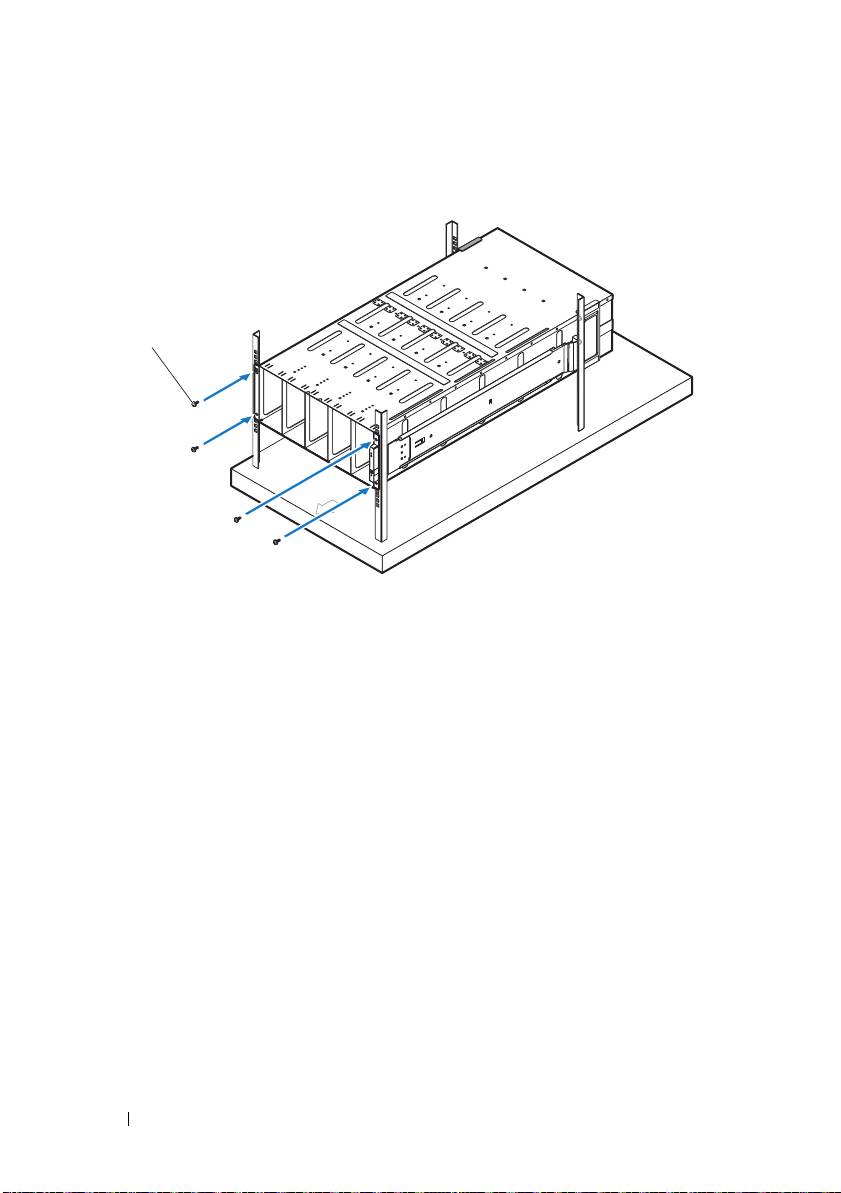
2
Secure the front of the enclosure to the left and right rack posts with the
four 10-32 screws
.
12
Getting Started With Your System
1
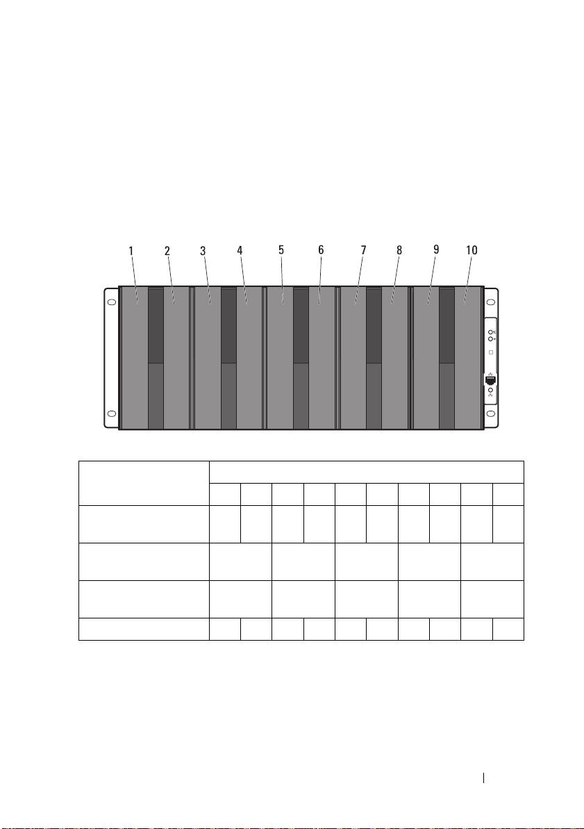
Sled Bay Numbering
The PowerEdge C8000 server enclosure is divided into ten vertical bays. A
C8220 single-wide compute sled occupies one sled bay in the server enclosure
and a C8220X double-wide compute sled or C8000XD storage sled occupies
two sled bays in the server enclosure. When installing a sled module into the
server enclosure, you should install the sled module in sled bay 1 first, then
work toward the right of the enclosure.
Sled Bays
Sled module type
a
a
12345
6
78910
C8220 single-wide
√√√√√√√√√√
compute sled
C8220X double-wide
√√√√√
compute sled
C8000XD storage
√√√√√
b
sled
c
Power sled
⎯⎯
⎯
⎯
√
√
⎯
⎯
⎯
⎯
a. Sled bays 5 and 6 support installation of two power sleds or two C8220 compute sleds or a
combination of the two sled types.
b. For server enclosure with internal power source, install C8000XD storage sleds in sled bays 3 to 10
only.
c. Install power sleds in sled bays 5 and 6 only.
Getting Started With Your System
13
Populating the System
CAUTION:
To ensure proper operation and cooling, all bays in the enclosure must
be populated at all times with either a sled or with a sled blank.
CAUTION:
To maintain proper system cooling, all empty hard-drive slots must
have hard-drive blanks installed.
Install all components into the PowerEdge C8000 server enclosure.
• To install a
C8220 single-wide
compute sled, slide the new sled into the
enclosure until the sled is fully seated and the release latch snaps into
place.
• To install a
C8220X double-wide compute sled, slide the new sled into
the enclosure until the sled is fully seated and the release latch snaps
into place.
• To install a
C8000XD storage sled, slide the new sled into the enclosure
until the sled is fully seated and the release tab snaps into place.
• To install a power sled, slide the new sled into the enclosure until the sled
is fully seated and the release latch snaps into place.
• To install a double-wide sled blank, slide the blank into the enclosure until
it is fully seated and the release latches snap into place.
• To install a single-wide sled blank, slide the blank into the enclosure until
it is fully seated and the release latch snaps into place.
14
Getting Started With Your System
Install the External PDU Into the Rack
WARNING:
Whenever you need to lift the system, get others to assist you. To
avoid injury, do not attempt to lift the system by yourself.
NOTE:
The PDU device illustrations are provided as reference only. See PDU
device documentation for more information about the PDU device.
NOTE:
The PDU mounting brackets are marked L and R. The rail marked "L"
attaches to the left of the PDU device and the rail marked "R" attaches to the right of
the PDU device.
WARNING:
Do not connect or disconnect power cables to the PDU device while
the PDU is energized.
WARNING:
Turn off the PDU breaker switches to avoid potentially serious or
fatal electric shock.
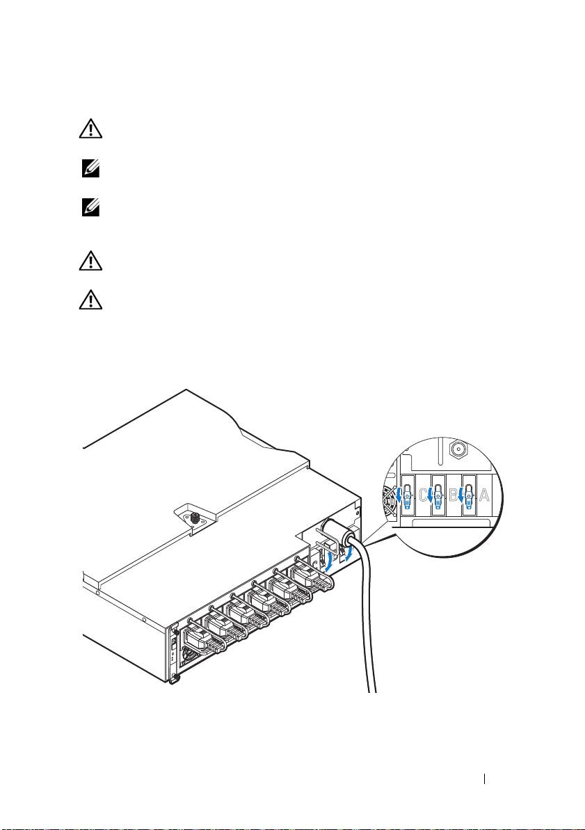
1
Turn off the PDU breaker switches by moving the A, B, and C breaker
switches to the "OFF" position.
2
Disconnect the PDU from the power source.
Getting Started With Your System
15
OFFOFFOFF
3
Remove the power cable interface box (PCIB) module.
a
Remove the two screws
securing the PCIB module.
b
Grasp the PCIB handle and pull it out of it’s bay
.
4
Attach the mounting brackets to the sides of the PDU.
a
Affix the ten screws
to the left and right sides of the PDU.
b
Position the left mounting bracket marked "L" to align the screw holes
with the screws on the PDU and slide the mounting bracket toward
the back of the PDU until it locks into place
.
c
Position the right mounting bracket marked "R" to align the screw
holes with the screws on the PDU and slide the mounting bracket
toward the back of the PDU until it locks into place
.
16
Getting Started With Your System
1
2
5
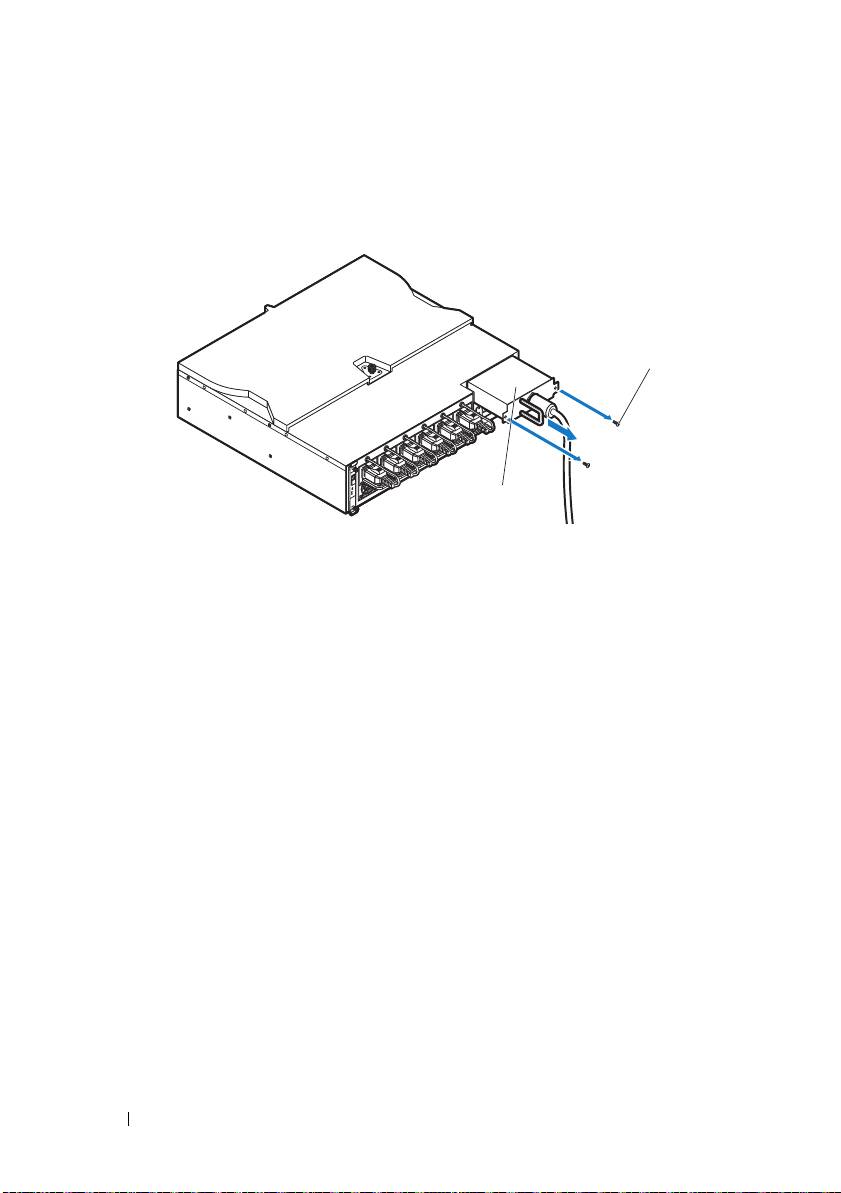
Install the snorkel to the PDU.
a
Remove the air duct from the snorkel.
b
Align the air duct
with the front of the PDU.
c
Secure the air duct to the front of the PDU with the two screws
.
Getting Started With Your System
17
2
1
d
Align the snorkel with the rack posts.
e
Secure the snorkel to the rack posts with the four screws
.
18
Getting Started With Your System
1
2
1
FRONT
