Dell PowerEdge C5230: instruction
Class: Household, kitchen appliances, electronics and equipment
Type: Computer
Manual for Dell PowerEdge C5230
Table of contents
- Notes, Cautions, and Warnings
- CAUTION: Restricted Access Location Installation and Configuration Unpacking the System Installing the Tool-Less Rail Solution
- Figure 1-1. Unlocking the Rail Latches Figure 1-2. Aligning the Rails on the Rack
- Installing the System Empting the System Chassis Figure 1-3. Unplugging the Power Cable from the Power Supply Unit Figure 1-4. Releasing the Power Supply Unit Handle
- Figure 1-5. Removing the Power Supply Unit Figure 1-6. Removing the Sled
- Figure 1-7. Securing the Chassis on the Rails
- Populating the System Figure 1-8. Installing the Power Supply Unit Figure 1-9. Securing the Power Supply Unit Handle
- Figure 1-10. Connecting the Power Cable to the Power Supply Unit Figure 1-11. Locating the Power Supply Unit Sockets
- Figure 1-12. Installing the Sled Connecting the Keyboard, Mouse, and Monitor Figure 1-13. Connecting Perhipherals
- Connecting the Power Cables Figure 1-14. Connecting Power Cables Turning On the System Complete the Operating System Setup
- Other Information You May Need NOM Information (Mexico Only)
- Technical Specifications Processor (Per System Board) Memory (Per System Board) Drives (Per System Board) Connectors (Per System Board) Video
- Power Heat Dissipation Physical
- Environmental
- Environmental (continued) Acoustics
Dell PowerEdge C5230
Getting Started
With Your
System
Začínáme se systémem
Mise en route de votre système
Erste Schritte mit dem System
Τα πρώτα βήματα με το σύστημά σας
Rozpoczęcie pracy z systemem
Начало работы с системой
Introducción al sistema
www.dell.com | support.dell.com
תכרעמה םע הדובעה תליחת


Dell PowerEdge C5230
Getting Started
With Your
System
Regulatory Model B04S
www.dell.com | support.dell.com
Notes, Cautions, and Warnings
NOTE:
A NOTE indicates important information that helps you make better use of
your system.
CAUTION:
A CAUTION indicates potential damage to hardware or loss of data if
instructions are not followed.
WARNING:
A WARNING indicates a potential for property damage, personal
injury, or death.
____________________
© 2013 Dell Inc.
Trademarks used in this text: Dell™, the DELL logo, and PowerEdge™ are trademarks of Dell Inc.
®
®
®
Intel
and Intel
Xeon
are registered trademarks of Intel Corporation in the U.S. and other countries.
®
®
Microsoft
and Windows
are either trademarks or registered trademarks of Microsoft Corporation
®
®
in the United States and/or other countries. Red Hat
and Red Hat Enterprise Linux
are registered
trademarks of Red Hat, Inc. in the United States and/or other countries. SUSE™ is a trademark of
®
®
®
Novell Inc. in the United States and other countries. Citrix
, Xen
, and XenServer
are either
registered trademarks or trademarks of Citrix Systems, Inc. in the United States and/or other countries.
®
VMware
is a registered trademarks or trademarks of VMWare, Inc. in the United States or other
countries.
Regulatory Model B04S
2013 - 09 P/N VP70D Rev. A00
CAUTION:
Restricted Access Location
This server is intended for installation only in restricted access locations as
defined in Cl. 1.2.7.3 of IEC 60950-1: 2001 where both these conditions
apply:
• Access can only be gained by service persons or by users who have been
instructed about the reasons for the restrictions applied to the location and
about any precautions that shall be taken.
• Access is through the use of a tool or lock and key, or other means of
security, and is controlled by the authority responsible for the location.
Installation and Configuration
WARNING:
Before performing the following procedure, review and follow the
safety instructions that came with the system.
Unpacking the System
Unpack your system and identify each item.
Installing the Tool-Less Rail Solution
WARNING:
Whenever you need to lift the system, get others to assist you. To
avoid injury, do not attempt to lift the system by yourself.
WARNING:
The system is not fixed to the rack or mounted on the rails. To avoid
personal injury or damage to the system, you must adequately support the system
during installation and removal.
WARNING:
To avoid a potential electrical shock hazard, a third wire safety
grounding conductor is necessary for the rack installation. The rack equipment
must provide sufficient airflow to the system to maintain proper cooling.
CAUTION:
When installing rails in a square-hole rack it is important to ensure
that the square peg slides through the square holes.
CAUTION:
Square studs must be flush with the rack posts to install properly.
Installation and Configuration
3
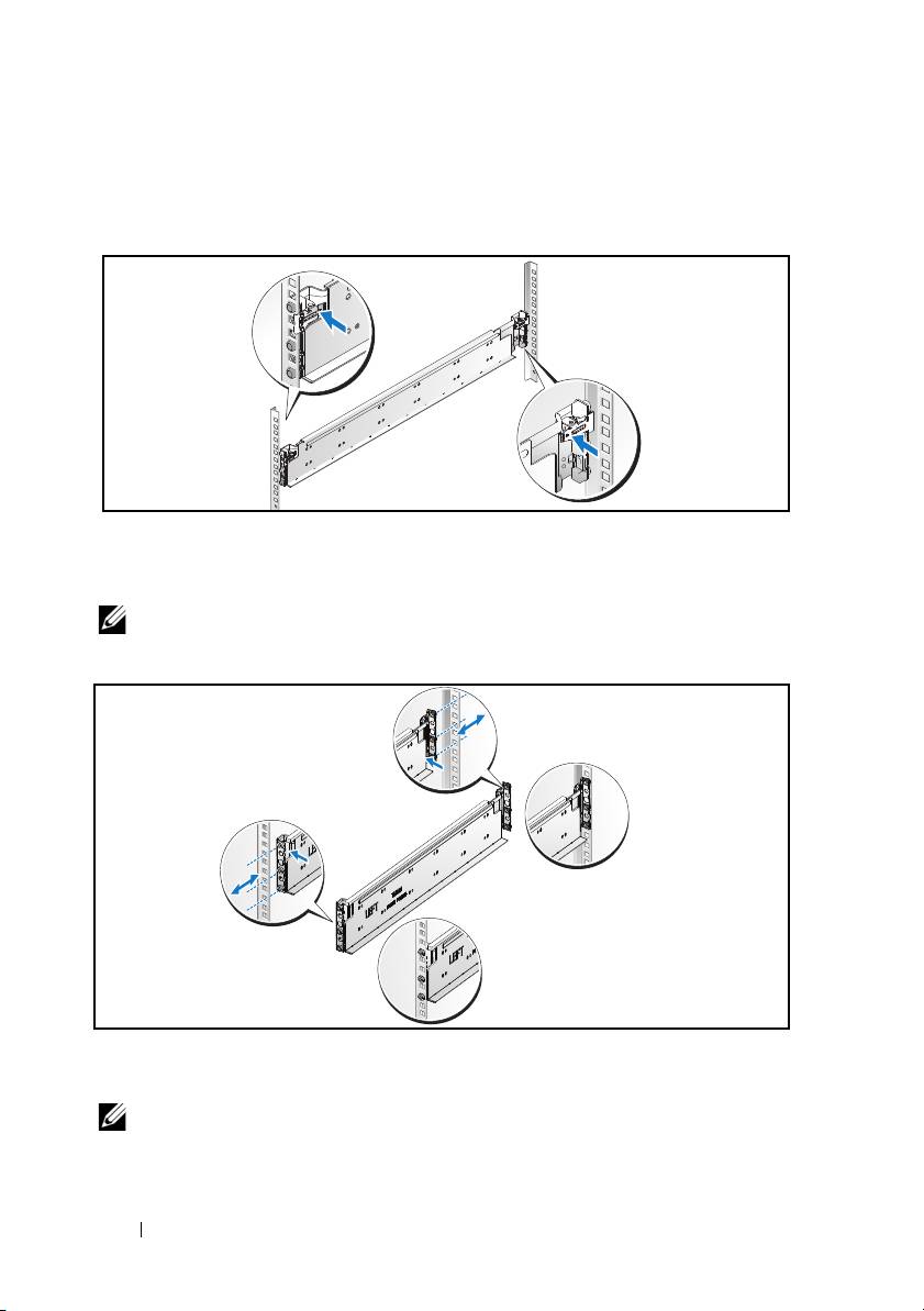
1
Pull on the latch release buttons on the end piece midpoints to open the
rail latches.
Figure 1-1. Unlocking the Rail Latches
2
Align the end pieces of the rails on the vertical rack flanges to seat the pegs
in the bottom hole of the first U and the top hole of the second U. Engage
the back end of the rail until the latch locks in place.
NOTE:
The rails can be used in both square-hole and round-hole racks.
Figure 1-2. Aligning the Rails on the Rack
3
Repeat steps 1 and 2 to position and seat the front end piece on the
vertical flange.
NOTE:
To remove the rails, pull on the latch release button on the end piece
midpoint and unseat each rail.
4
Installation and Configuration
Back
Front
Installing the System
Empting the System Chassis
WARNING:
Before installation, it is recommended that you remove the sleds and
power supplies from the system to reduce weight.
1
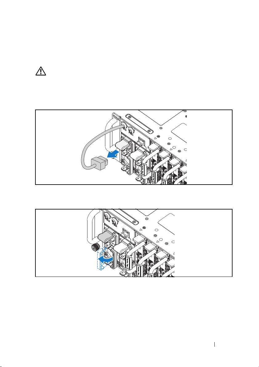
Unplug the power cable from the power supply unit.
Figure 1-3. Unplugging the Power Cable from the Power Supply Unit
2
Pull out the power supply unit handle.
Figure 1-4. Releasing the Power Supply Unit Handle
3
Press down on the release latch
.
Installation and Configuration
5
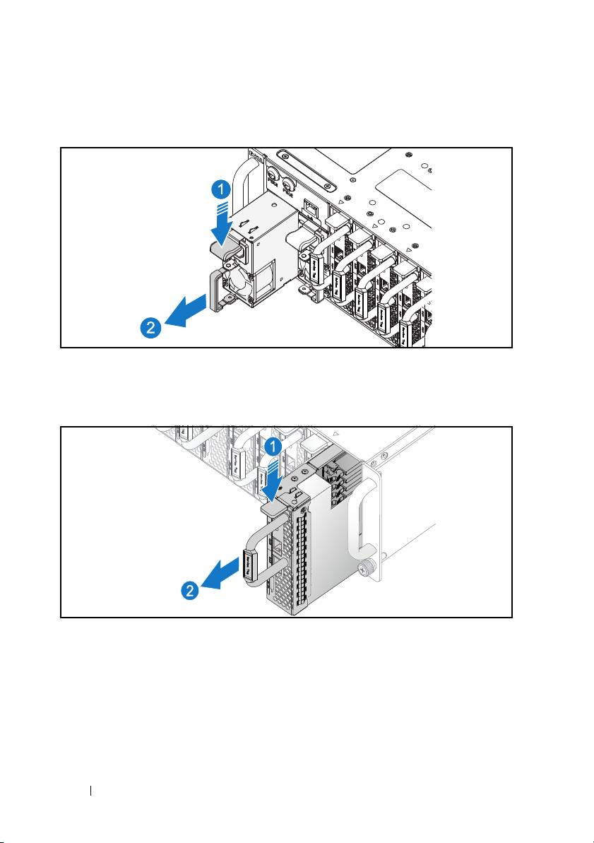
4
Pull the power supply unit out of the system
.
Figure 1-5. Removing the Power Supply Unit
5
Press the release latch down
.
6
Pull the sled out of the system
.
Figure 1-6. Removing the Sled
6
Installation and Configuration
Installing the System Into the Rack
WARNING:
Whenever you need to lift the system, get others to assist you. To
avoid injury, do not attempt to lift the system by yourself.
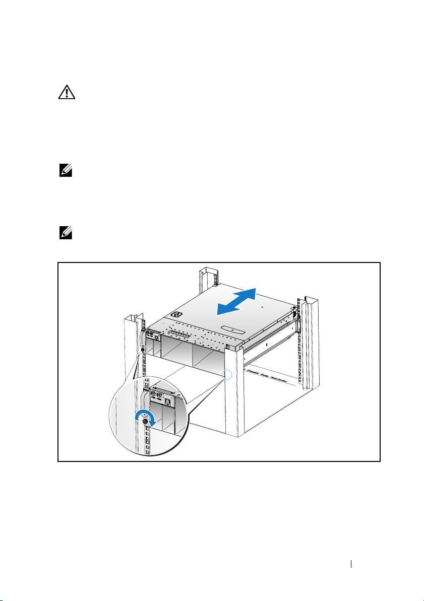
1
Slide the system into the rack.
2
If present, remove the chassis stabilizer shipping bracket (optional) from
the rack.
NOTE:
To transport systems already installed in the rack, ensure that the two
chassis stabilizer shipping brackets (optional) are in place.
3
Tighten the captive thumbscrews to secure the ears of the system to the
front of the rack.
NOTE:
Make sure the latch release mechanism is engaged correctly.
Figure 1-7. Securing the Chassis on the Rails
Installation and Configuration
7
Populating the System
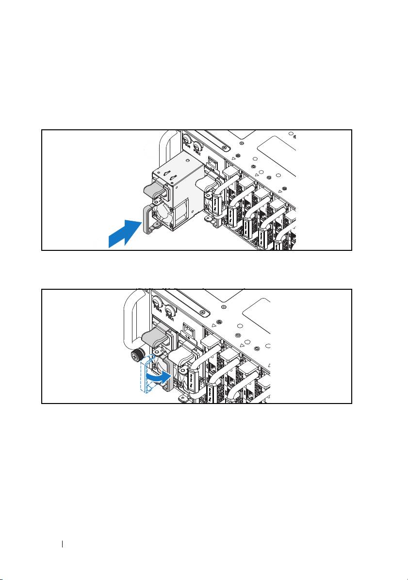
1
Push the power supply unit into the system until flush with the case and
the release latch locks.
Figure 1-8. Installing the Power Supply Unit
2
Close the power supply unit handle.
Figure 1-9. Securing the Power Supply Unit Handle
3
Plug the chassis power cable into the power supply unit.
8
Installation and Configuration
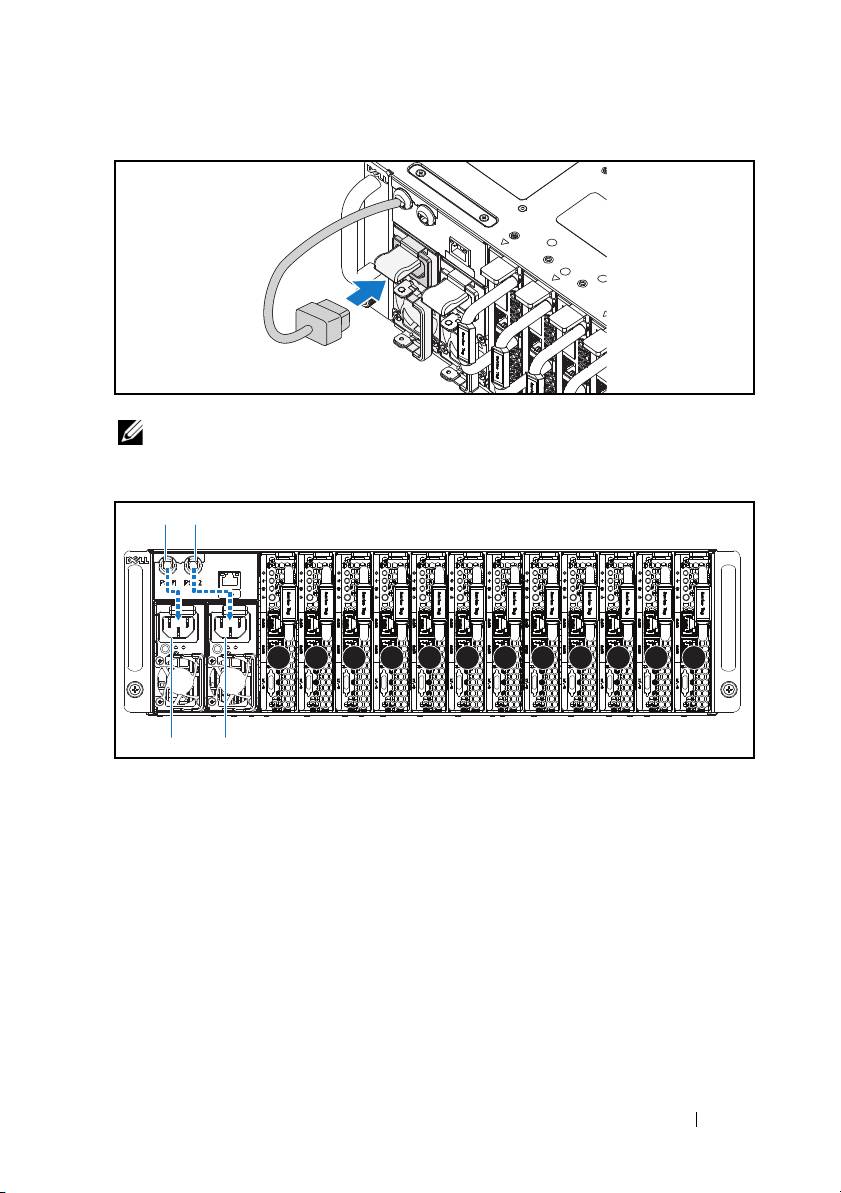
Figure 1-10. Connecting the Power Cable to the Power Supply Unit
NOTE:
The correct configuration of the integral chassis AC power cables to the
power supply unit sockets is shown in the following illustration.
Figure 1-11. Locating the Power Supply Unit Sockets
4
Push the sled into the system until flush with the case and the release latch
locks.
Installation and Configuration
9
PSU1 PSU2
1 2 3 4 5 6 7 8 9 10 11 12
PSU1 PSU2
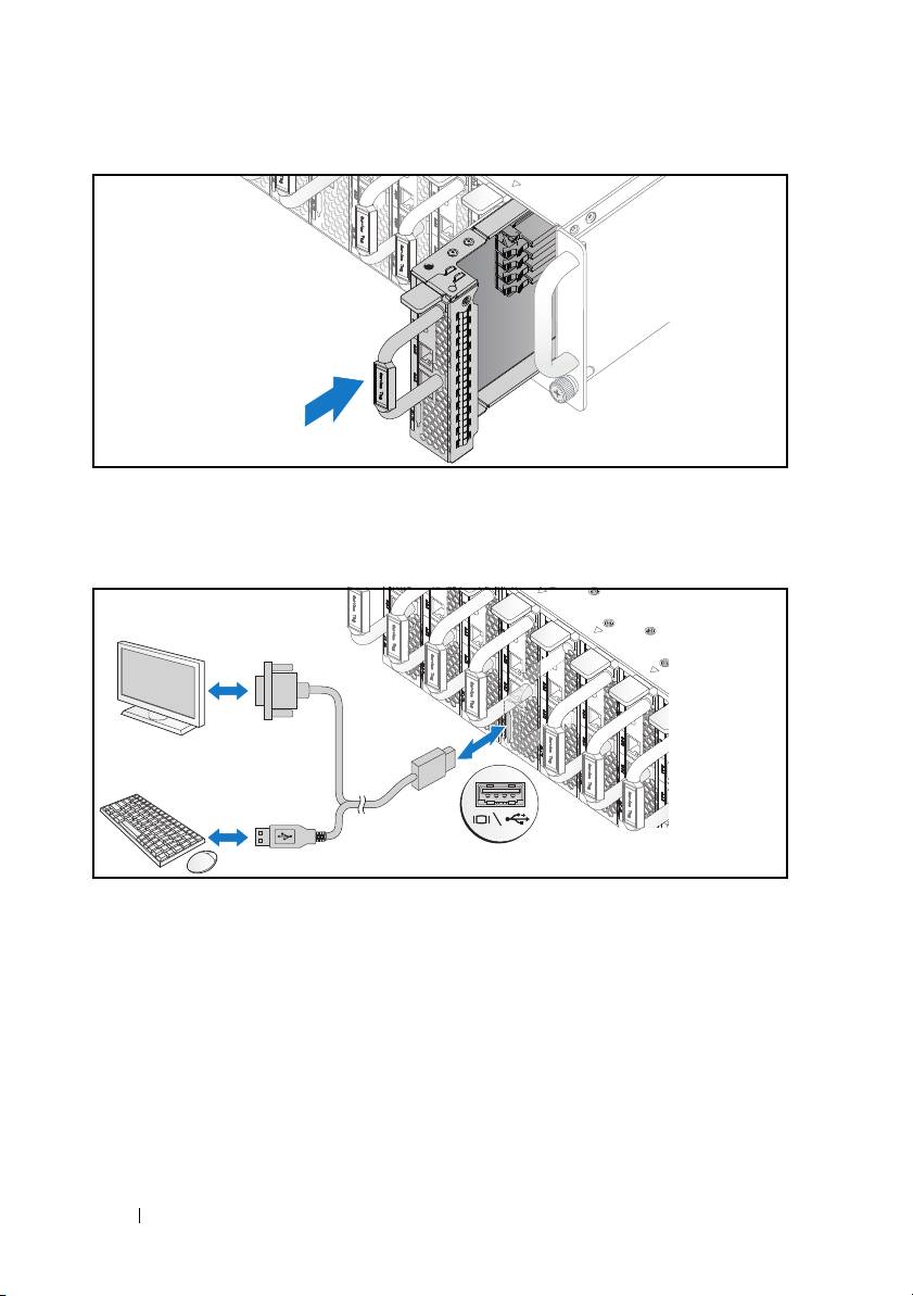
Figure 1-12. Installing the Sled
Connecting the Keyboard, Mouse, and Monitor
Figure 1-13. Connecting Perhipherals
The connector on the front of your system has an icon indicating which cable
to plug in. You can connect a keyboard, mouse, or monitor (optional).
10
Installation and Configuration
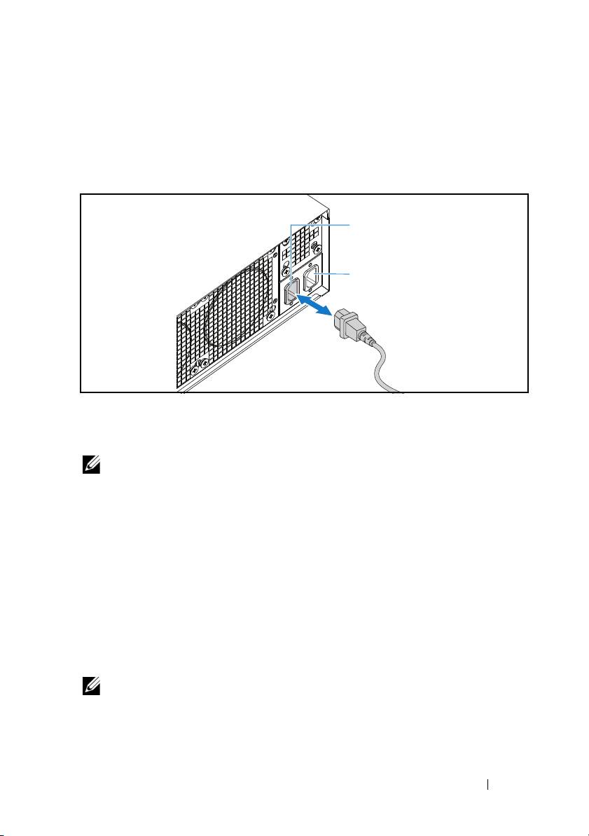
Connecting the Power Cables
1
On the back of the system, connect the main power cable to the system’s
power socket.
Figure 1-14. Connecting Power Cables
2
Plug the other end of the power cable into a grounded electrical outlet or a
separate power source such as an uninterrupted power supply or a power
distribution unit.
NOTE:
AC Port 1 provides power to PSU1, AC Port 2 provides power to PSU2. For
more information, see step 3 of Populating the System.
Turning On the System
When connected to a power source the system automatically powers on.
Complete the Operating System Setup
To install an operating system for the first time, see the installation and
configuration documentation for your operating system. Be sure the
operating system is installed before installing hardware or software not
purchased with the system.
NOTE:
For the latest information on supported operating systems, see
dell.com/ossupport.
Installation and Configuration
11
AC Port 2
AC Port 1

Other Information You May Need
WARNING:
See the safety and regulatory information that shipped with your
system. Warranty information may be included within this document or as a
separate document.
See the Hardware Owner’s Manual at dell.com/support/manuals for
information about system features, troubleshooting, and component
replacement.
Dell systems management application documentation provides information
about installing and using the systems management software. This document
is available online at dell.com/support/manuals.
NOTE:
Always check for updates on dell.com/support/manuals and read the
updates first because they often supersede information in other documents.
NOM Information (Mexico Only)
The following information is provided on the device described in this
document in compliance with the requirements of the official Mexican
standards (NOM):
Importer Dell Inc. de México, S.A. de C.V.
Paseo de la Reforma 2620-11° Piso
Col. Lomas Atlas
11950 México, D.F.
Model number B04S
Supply voltage 200-240 VAC
Frequency 50/60 Hz
Current consumption 9A for each power inlet
12
Installation and Configuration

Technical Specifications
Processor (Per System Board)
Processor type Intel Xeon Processor E3-1240v3, E3-
1280v3
Memory (Per System Board)
Architecture Dual Channel Unbuffered DDR3 1600
Memory module sockets 4
Memory module capacities
Minimum RAM 2 GB
Maximum RAM 32 GB
Drives (Per System Board)
Option 1: 2.5" hard drives
SATA 6 Gb (4 channels)
Option 2: 3.5" hard drives
SATA 6 Gb (2 channels)
Connectors (Per System Board)
Front
NIC 10/100/1G (RJ45)
2
USB 2.0 (through optional Y-cable)
2
Video (through optional Y-cable)
1
Video
Video type AST2300
Video memory 8 MB DDR3 SDRAM
Technical Specifications
13

Power
AC power supply (per power supply)
Wa tt ag e
1400 W
Voltage
200-240 VAC, 50/60 Hz
Heat dissipation
572.88 BTU/hr. max.
Maximum inrush current
55 A max.
Heat Dissipation
System chassis
12-sled
7.2 K BTU/hr. max.
Physical
Height 13 cm (5.1 in)
Width 44.7 cm (17.6 in)
Depth 75 cm (29.5 in)
Weight (loaded: maximum weight)
48.13 kg (106.11 lbs.)
12 sled configuration
Weight (empty)
32.02 kg (70.59 lbs.)
12 sled configuration
14
Technical Specifications

Environmental
NOTE:
For additional information about environmental measurements for specific
system configurations, see www.dell.com/environmental_datasheets.
Temperature
Operating
10°C to 35°C (50°F to 95°F) with a
maximum temperature gradation of 10°C
(per hour)
NOTE:
For altitudes above 2,950 feet, the
maximum operating temperatures derated to
1°F/550 ft.
Storage
–40°C to 65°C (-40°F to 149°F) with a
maximum temperature gradation of 20°C
per hour
Relative Humidity
Operating
20% to 80% (noncondensing) with a
maximum humidity gradation of 10% per
hour
Storage
5% to 85% (noncondensing)
Maximum vibration
Operating
0.26 Grms at 5–350 Hz
Storage
1.87 Grms at 10–500 Hz for 15 minutes
Maximum shock
Operating
One shock pulse in the positive z axis (one
pulse on each side of the system) of 31 G for
2.6 ms in the operational orientation
Storage
Six consecutively executed shock pulses in
the positive and negative x, y, and z axes
(one pulse on each side of the system) of
71 G for up to 2 ms.
Six consecutively executed shock pulses in
the positive and negative x, y, and z axes
(one pulse on each side of the system) of
22 G faired square wave pulse with velocity
change at 200 inches/second
Technical Specifications
15

Environmental (continued)
Altitude
Operating
-16 to 3,048 m (-50 to 10,000 ft.)
Storage
-16 to 10,600 m (-50 to 35,000 ft.)
Airborne Contaminant Level
Class
G1 as defined by ISA-S71.04-1985
Acoustics
Sound Power (Units: LwAd-UL,bels)
Idle in 23 ± 2
°
C ambient
<= 7.0
CPU with 50% loading & HDD stress
<= 7.5
in 23 ± 2
°
C ambient
NOTE:
LwAd-UL is the upper limit sound power level (LwAd) calculated by ISO 9296
(1988) and measured in accordance with ISO7779 (1999).
16
Technical Specifications

Dell PowerEdge
C5230
Začínáme
se systémem
Směrnicový model B04S
www.dell.com | support.dell.com

Poznámky a upozornění
POZNÁMKA:
POZNÁMKA označuje důležité informace, které pomáhají lepšímu využití
systému.
UPOZORNĚNÍ:
UPOZORNĚNÍ označuje nebezpečí poškození hardwaru nebo ztráty
dat v případě nedodržení pokynů.
VAROVÁNÍ:
VAROVÁNÍ upozorňuje na potenciální nebezpečí poškození majetku,
úrazu nebo smrti.
____________________
© 2013 Dell Inc.
Ochranné známky použité v tomto textu: Dell™, logo DELL a PowerEdge™ jsou ochranné známky
®
®
®
společnosti Dell Inc. Intel
a Intel
Xeon
jsou registrované ochranné známky společnosti Intel
®
®
Corporation v USA a dalších zemích. Microsoft
a Windows
jsou ochranné známky nebo
registrované ochranné známky společnosti Microsoft Corporation v USA a dalších zemích.
®
®
Red Hat
a Red Hat Enterprise Linux
jsou registrované ochranné známky společnosti Red Hat,
Inc. v USA a dalších zemích. SUSE™ je ochranná známka společnosti Novell Inc. v USA a dalších
®
®
®
zemích. Citrix
, Xen
a XenServer
jsou registrované ochranné známky nebo ochranné známky
®
společnosti Citrix Systems, Inc. v USA a dalších zemích. VMware
je registrovaná ochranná známka
společnosti VMware, Inc. v USA a dalších zemích.
Směrnicový model B04S
2013 - 09 Č. dílu VP70D Rev. A00
