Dell PowerVault DP600: instruction
Class: Computer Hardware
Type:
Manual for Dell PowerVault DP600
Table of contents
- Notes, Notices, and Cautions
- Contents
- System Features
- The system board includes the following features:
- Supported Operating Systems Other Information You May Need Obtaining Technical Assistance
- Installation and Configuration Unpacking the System
- Installing the Rails and System in a Rack
- Connecting the Keyboard, Mouse, and Monitor Connecting the Power
- Installing the Power Cord Retention Bracket Turning on the System
- Installing the Bezel Complete the 0perating System Setup Technical Specifications Processor Expansion Bus
- Memory Drives Connectors
- Connectors (continued) Video Power Physical
- Physical (continued) Environmental

Dell™ PowerVault™
600 Systems
Getting Started
With Your System
Začínáme se systémem
Guide de mise en route
Erste Schritte mit dem System
Τα πρώτα βήµατα Με το σύστηµά σας
Rozpoczęcie pracy z systemem
Начало работы с системой
Procedimientos iniciales con el sistema
תכרעמה ע הדובעה תליחת
Model MVT01


Dell™ PowerVault™ 600
Systems
Getting Started
With Your System
Model MVT01

Notes, Notices, and Cautions
NOTE: A NOTE indicates important information that helps you make better use of
your computer.
NOTICE: A NOTICE indicates either potential damage to hardware or loss of data
and tells you how to avoid the problem.
CAUTION: A CAUTION indicates a potential for property damage, personal injury,
or death.
____________________
Information in this document is subject to change without notice.
© 2007 Dell Inc. All rights reserved.
Reproduction in any manner whatsoever without the written permission of Dell Inc. is strictly
forbidden.
Trademarks used in this text: Dell, the DELL logo, and PowerVault, are trademarks of Dell Inc.;
Intel Core and Core 2 Duo are trademarks and Intel, Pentium and Xeon are registered trademarks of
Intel Corporation in the U.S. and other countries; Microsoft, Windows, and Windows Storage Server
are either trademarks or registered trademarks of Microsoft Corporation in the United States and/or
other countries.
Other trademarks and trade names may be used in this document to refer to either the entities claiming
the marks and names or their products. Dell Inc. disclaims any proprietary interest in trademarks and
trade names other than its own.
Model MVT01
September 2007 P/N CX202 Rev. A00

Contents
System Features . . . . . . . . . . . . . . . . . . . . . . 5
Supported Operating Systems
. . . . . . . . . . . . . . . 7
Other Information You May Need
. . . . . . . . . . . . . 7
Obtaining Technical Assistance
. . . . . . . . . . . . . 7
Installation and Configuration
. . . . . . . . . . . . . . . 8
Unpacking the System
. . . . . . . . . . . . . . . . 8
Installing the Rails and System in a Rack
. . . . . . 9
Connecting the Keyboard, Mouse, and Monitor
. . 10
Connecting the Power
. . . . . . . . . . . . . . . 10
Installing the Power Cord Retention Bracket
. . . 11
Turning on the System
. . . . . . . . . . . . . . . 11
Installing the Bezel
. . . . . . . . . . . . . . . . . 12
Complete the 0perating System Setup
. . . . . . . . . . 12
Technical Specifications
. . . . . . . . . . . . . . . . 12
Index . . . . . . . . . . . . . . . . . . . . . . . . . . . . . . . 17
Contents 3

4 Contents

System Features
The major hardware and software features of your system include:
®
®
• One or two Dual-Core Intel
Xeon
Processors 5000 Sequence.
• Support for symmetric multiprocessing (SMP), which is available on systems
with two Intel Xeon processors. SMP greatly improves overall system
performance by dividing processor operations between independent
processors. To take advantage of this feature, you must use an operating
system that supports multiprocessing.
NOTE: If you decide to upgrade your system by installing a second processor,
you must order the processor upgrade kits from your supplier. Not all versions
of the Intel Xeon processor will work properly as additional processors. The
upgrade kit contains the correct version of the processor, heat sink, and fan
as well as the instructions for performing the upgrade.
• A minimum of 512 MB of 533 or 667 MHz (when available), Fully
Buffered DIMMs (FBD), upgradable to a maximum of 48 GB by installing
combinations of 256-MB, 512-MB, 1-GB, 2-GB, or 4-GB memory modules
in the twelve memory module sockets on the system board.
The system also features redundant memory, which provides memory
sparing or memory mirroring. Either feature is available if eight or twelve
identical memory modules are installed.
• Support for up to ten 3.5-inch, internal hot-pluggable Serial-Attached
SCSI (SAS) or SATA hard drives (eight 3.5-inch internal hard drives with
hot-pluggable backplane board, and support for two additional
hot-pluggable 3.5-inch drives in the peripheral bay using the optional
1x2 flexbay backplane board).
• Peripheral bay provides support for an optional optical drive and an
optional half-height tape backup unit (TBU). A full-height TBU is
supported with the 1x2 flexbay bracket removed.
• An optional single, 1.44-MB, 3.5-inch diskette drive.
• An optional CD, DVD, or combination CD-RW/DVD drive.
NOTE: DVD devices are data only.
• An intrusion switch that signals the appropriate systems management
software if the top cover is opened.
• Up to two hot-pluggable, 930-W power supplies in a 1 + 1 redundant
configuration.
• Six hot-pluggable system cooling fans.
Getting Started With Your System 5

The system board includes the following features:
• Six PCI slots located in an expansion-card cage. Slots 1 and 2 are 3.3-V,
64-bit, 133-MHz PCI-X slots; slot 3 is a 3.3-V, PCIe x8 lane; slots 4 through 6
are 3.3-V, PCIe x4 lanes. Expansion-card slots accommodate full-height,
full-length expansion cards. PCIe slots accommodate up to x8 expansion
cards.
• Dedicated PCI slot for an integrated SAS host bus adapter or an optional
integrated RAID controller card with 256 MB of cache memory and a
RAID battery.
NOTE: System boot is not supported from an external device attached to a
SAS or SCSI adapter, including SAS 5/E, PERC 5/E, or PERC 4e/DC. Contact
your technical support provider for the latest support information about
booting from external devices.
• Two integrated Gigabit Ethernet NICs, capable of supporting 10-Mbps,
100-Mbps, and 1000-Mbps data rates.
• Six USB 2.0-compliant connectors (two on the front and four on the back)
capable of supporting a diskette drive, a CD-ROM or DVD-ROM drive,
a keyboard, a mouse, or a USB flash drive.
• Optional remote access controller (RAC) for remote systems management.
• An integrated VGA-compatible video subsystem with an ATI ES1000,
33-MHz PCI video controller. This video subsystem contains 16 MB of
DDR SDRAM video memory (nonupgradable). Maximum resolution is
1600 x 1200 with 64 K colors; true-color graphics are supported in the
following resolutions: 640 x 480, 800 x 600, 1024 x 768, 1152 x 864, and
1280 x 1024. When the optional RAC is installed, the video resolution
is 1024 X 768.
• Systems management circuitry that monitors operation of the system fans
as well as critical system voltages and temperatures. The systems
management circuitry works in conjunction with the systems management
software.
• Standard baseboard management controller with serial access.
• Back-panel connectors include one serial, one video, four USB, and
two NIC connectors.
6 Getting Started With Your System

• Front-panel connectors include a video and two USB connectors.
• Front-panel 1x5 LCD for system ID and error messaging.
• System ID button on the front and back panels.
For more information about specific features, see "Technical Specifications"
on page 12.
Supported Operating Systems
®
• Microsoft
Windows Storage Server™ 2003 R2 Express Edition (x64)
• Microsoft
Windows Storage Server 2003 R2 Workgroup Edition (x64)
Other Information You May Need
CAUTION: The Product Information Guide provides important safety and
regulatory information. Warranty information may be included within this
document or as a separate document.
• The
Rack Installation Instructions
or
Rack Installation Guide
included
with your rack solution describes how to install your system into a rack.
• The
Hardware Owner’s Manual
provides information about system
features and describes how to troubleshoot the system and install or
replace system components. The
Hardware Owner’s Manual
is available
on the CDs that came with your system or from your technical provider.
• CDs included with your system provide documentation and tools for
configuring and managing your system.
• Release notes or readme files may be included to provide last-minute
updates to the system or documentation or advanced technical reference
material intended for experienced users or technicians.
Obtaining Technical Assistance
If you do not understand a procedure in this guide or if the system does not
perform as expected, see your Hardware Owner’s Manual.
Getting Started With Your System 7
Installation and Configuration
CAUTION: Before performing the following procedure, read and follow the
safety instructions and important regulatory information in your Product
Information Guide.
This section describes the steps to set up your system for the first time. The
illustrations that follow show a rack-mounted system, but the installation
procedure applies in large part to a stand-alone tower system. In place of the
rack installation in step 2, refer to the documentation included with your
system on installing the stabilizer feet on your system.
CAUTION: Installing the feet on a stand-alone tower system is necessary to
provide a stable foundation for the system. Failure to install the feet poses the
risk of having the system tip over, possibly causing bodily injury or damage to
the system.
CAUTION: Whenever you need to lift the system, get others to assist you. To avoid
injury, do not attempt to lift the system by yourself.
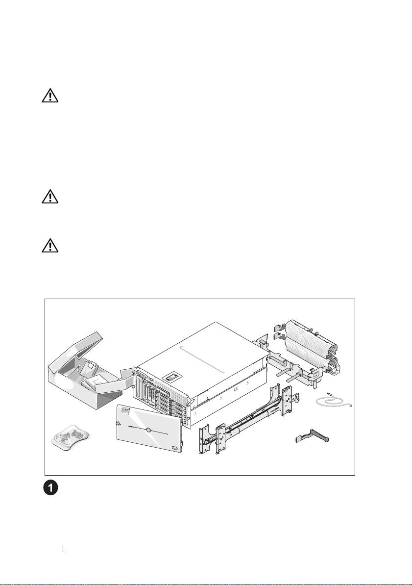
Unpacking the System
Unpack your system and identify each item.
Keep all shipping materials in case you need them later.
8 Getting Started With Your System
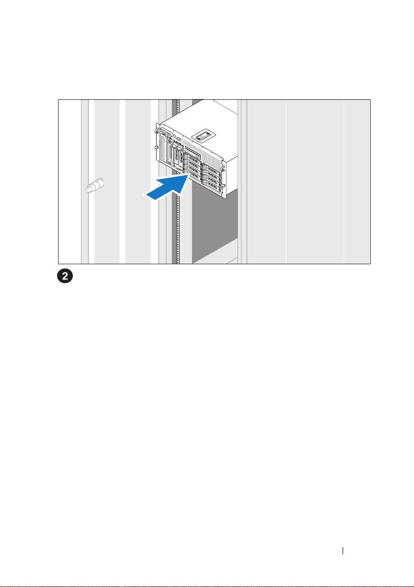
Installing the Rails and System in a Rack
Once you have read the "Safety Instructions" located in the rack installation
documentation for your system, install the rails and the system in the rack.
See your rack installation documentation for instructions on installing
your system in a rack.
For a tower system, see the documentation included with your system on
installing the system stabilizer feet.
Getting Started With Your System 9
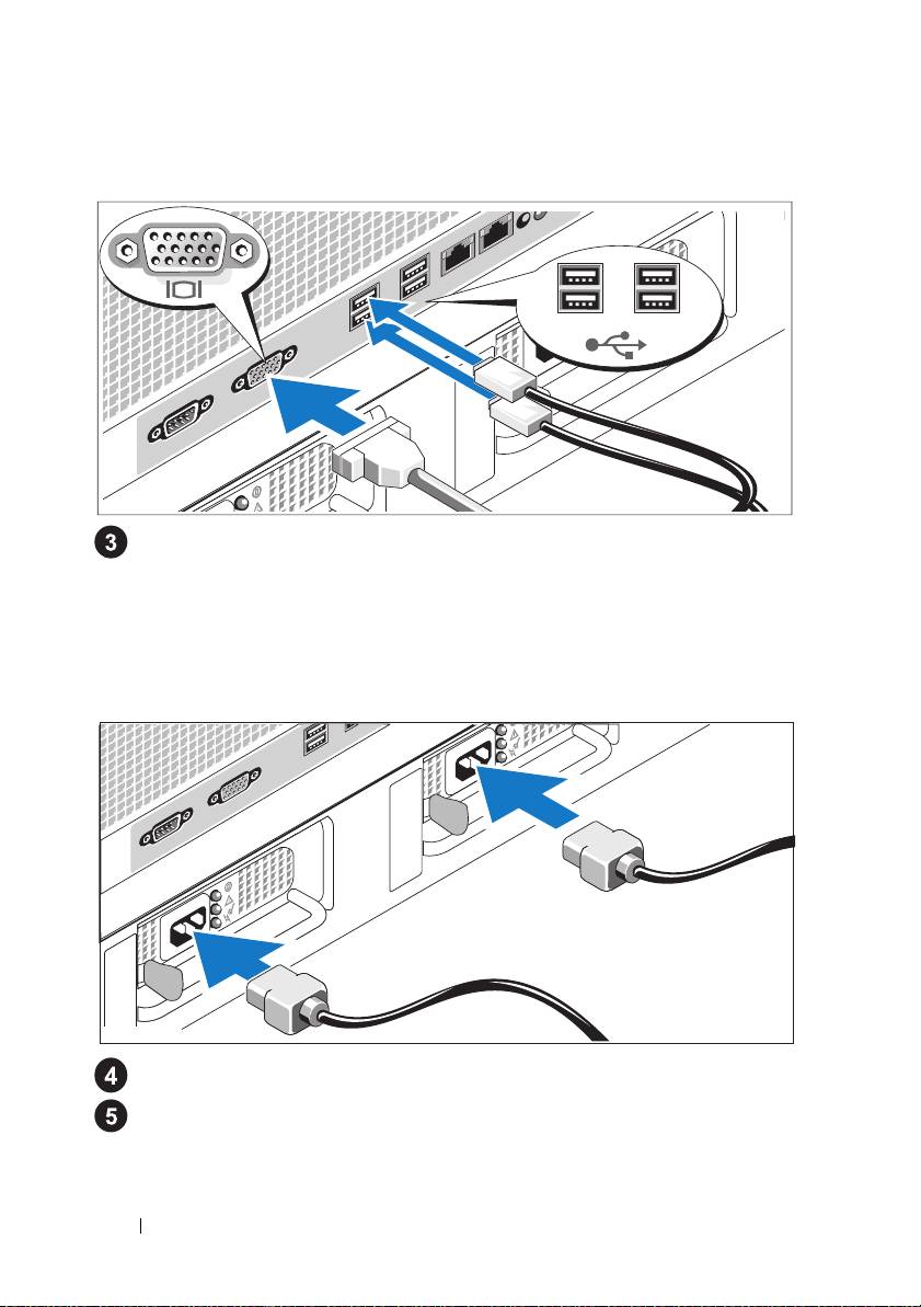
Connecting the Keyboard, Mouse, and Monitor
Connect the keyboard, mouse, and monitor (optional).
The connectors on the back of your system have icons indicating which cable
to plug into each connector. Be sure to tighten the screws (if any) on the
monitor's cable connector.
Connecting the Power
Connect the system’s power cable(s) to the system.
Plug the other end of the cable into a grounded electrical outlet or a
separate power source such as an uninterrupted power supply (UPS) or a
power distribution unit (PDU).
10 Getting Started With Your System
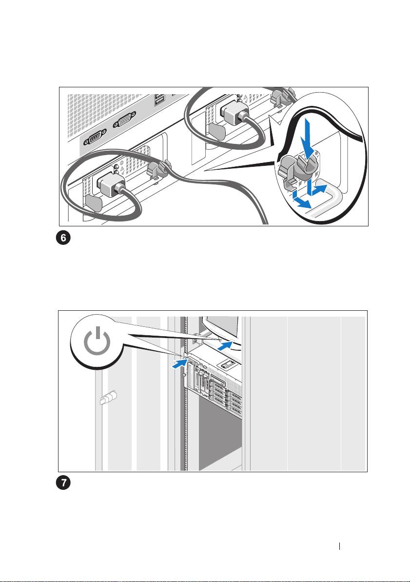
Installing the Power Cord Retention Bracket
Attach the power cord retention bracket on the right bend of the power
supply handle. Bend the system power cable into a loop as shown in the
illustration and attach to the bracket’s cable clasp. Repeat the procedure
for the second power supply.
Turning on the System
Turn on the system and monitor (optional).
Press the power button on the system and the monitor. The power
indicators should light. Adjust the monitor’s controls until the displayed
image is satisfactory.
Getting Started With Your System 11
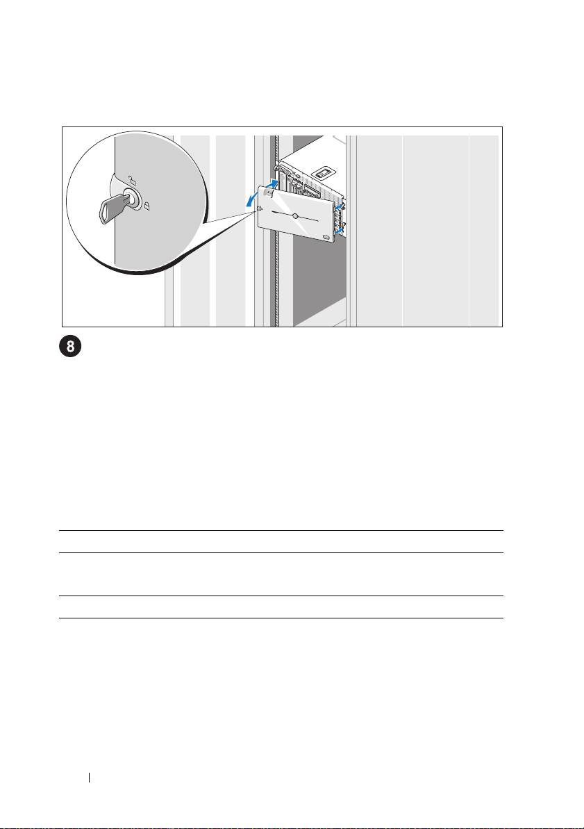
Installing the Bezel
Install the bezel (optional).
Complete the 0perating System Setup
If you purchased a preinstalled operating system, see the operating system
documentation that ships with your system. To install an operating system for the
first time, see the
Quick Installation Guide
. Be sure the operating system is installed
before installing hardware or software not purchased with the system.
Technical Specifications
Processor
Processor type One or two Dual-Core Intel Xeon Processors 5000
Sequence
Expansion Bus
Bus type PCI, PCI-X, PCIe
Expansion slots
PCI-X
two full-height, full-length 3.3-V, 64-bit, 133-MHz
(slots 1 and 2)
PCIe
one x8 lane, 3.3-V (slot 3)
three x4 lanes, 3.3-V (slots 4 through 6)
12 Getting Started With Your System

Memory
Architecture 533 or 667 MHz (when available) Fully Buffered
DIMMs (FBD)
Memory module sockets twelve 240-pin
Memory module capacities 256 MB, 512 MB, 1 GB, 2 GB, or 4 GB
Minimum RAM 512 MB (two 256-MB module)
Maximum RAM 48 GB
Drives
Hard drives up to ten 3.5-inch, internal, hot-plug SAS or
SATA
• eight drives in the internal drive bay
• two drives in the optional 1x2 flexbay
backplane expansion
Diskette drive one optional 3.5-inch, 1.44-MB
external optional USB 3.5-inch, 1.44-MB
Optical drive one optional
CD, DVD, or combination
CD-RW/DVD
NOTE:
DVD devices are data only.
external optional USB CD-ROM
external optional USB DVD-ROM
Flash drive external optional USB
Connectors
Back
NIC
Two TOE-capable RJ-45 (for integrated 1-GB
NICs)
Serial
9-pin, DTE, 16550-compatible
USB
Four 4-pin, USB 2.0-compliant
Video
15-pin VGA
Getting Started With Your System 13

Connectors (continued)
Front
Video
15-pin VGA
USB
Two 4-pin, USB 2.0-compliant
Video
Video type ATI ES1000 video controller; VGA connectors
Video memory 16 MB of DDR SDRAM
Power
AC power supply (per power supply)
Wa tt ag e
930 W
Voltage
90–264 VAC, autoranging, 47–63 Hz
Heat dissipation
2697 BTU/hr maximum
Maximum inrush current
Under typical line conditions and over the entire
system ambient operating range, the inrush
current may reach 55 A per power supply for
10 ms or less
Batteries
System battery
CR 2032 3.0-V lithium ion coin cell
RAID battery (optional)
4.1-V lithium ion
Physical
Rack
Height
21.77 cm (8.57 in)
Width
44.27 cm (17.43 in) chassis only
48.27 cm (19 in) with rack flanges
Depth
66.13 cm (26.04 in) does not include control panel or
bezel; control panel adds an additional 1.3 cm (.51 in)
Weight (maximum
45.36 kg (100 lb)
configuration)
14 Getting Started With Your System

Physical (continued)
Tower (without bezel)
Height
47.89 cm (18.85 in) with feet, no casters
Width
22.66 cm (8.92 in)
Depth
66.13 cm (26.04 in) does not include control panel or
bezel; control panel adds an additional 1.3 cm (.51 in)
Weight (maximum
49.9 kg (110 lb)
configuration)
Environmental
NOTE: For additional information about environmental measurements for specific
system configurations, contact your technical support provider.
Temperature
Operating
10° to 35°C (50° to 95°F)
Storage
–40° to 65°C (–40° to 149°F)
Relative humidity
Operating
20% to 80% (noncondensing) with a maximum
humidity gradation of 10% per hour
Storage
5% to 95% (noncondensing)
Maximum vibration
Operating
0.26 G from 5–350Hz for 2 min in the Z axis
Storage
1.54 G from 10–250 Hz for 15 min in all
orientations
Maximum shock
Operating
One shock pulse in the positive z axis (one pulse
on each side of the system) of 41 G for up to 2 ms
Storage
Six consecutively executed shock pulses in the
positive and negative x, y, and z axes (one pulse
on each side of the system) of 71 G for up to 2 ms
Altitude
Operating
–16 to 3048 m (–50 to 10,000 ft)
Storage
–16 to 10,600 m (–50 to 35,000 ft)
Getting Started With Your System 15

16 Getting Started With Your System

Index
C
R
combination CD-RW/DVD, 5
remote access controller
remote systems management, 6
remote access controller card, 6
E
remote systems management
expansion-card cage, 6
remote access controller card, 6
I
S
installation and configuration, 8
supported Operating Systems, 7
integrated RAID controller, 6
symmetric multiprocessing
(SMP), 5
system features, 5
M
CD drive, 5
diskette drive, 5
memory, 5
DVD drive, 5
interleaving, 5
memory, 5
NICs, 6
power supply, 5
N
processors, 5
NICs, 6
remote access controller card, 6
symmetric multiprocessing
(SMP), 5
P
USB, 6
video controller, 6
processors, 5
Index 17

T
technical assistance, 7
technical specifications, 12
V
video controller, 6
18 Index
