Dell UPS 10000R: Manufacturer Type Rating
Manufacturer Type Rating: Dell UPS 10000R
Table of contents
- Notes and Warnings
- System Features
- Finding Information What are You Looking For? Find It Here
- Installation and Startup
- Unpacking the Cabinet To unpack the system: Using a forklift or pallet jack, move the shipping carton and pallet near the rack where you will install the UPS. Detach and remove the outer carton.
- Remove the two accessory boxes tucked into the channels in the top Styrofoam section. Open the accessory boxes and set them on a flat, stable surface nearby. Remove the top Styrofoam section and set it on a flat, stable surface nearby.
- Remove both retaining brackets from the UPS: Ensure all battery connectors are disconnected.
- Remove the battery trays from the UPS:
- With one person on each side, carefully lift the cabinet out of the styrofoam using the handles on the cardboard. Place the cabinet on a flat, stable surface in a protected area near the rack where you will install it.
- Rackmount Setup To install the UPS in a rack:
- Installing the Rails Remove the rails from the rail kit accessory box. Select the proper holes in the rail for positioning the cabinet in the desired location in the rack. Locate the rails at the bottom of the 5U space allocated for the UPS. Position the left and right rails as illustrated. Attach the the left and right rails to the rack:
- Installing and Securing the Cabinet Slide the cabinet onto the rails and into the rack. Secure the front of the cabinet to the rack using the four thumbscrews on the mounting brackets. Tighten the thumbscrews clockwise by hand; do not use power tools. Installing the Battery Trays Locate the battery trays you placed near the rack.
- Install the battery trays: Tuck the loop tabs into the plastic sleeve on the front of each battery tray to move them out of the way. Connecting Internal Battery Connectors Connect the internal battery connectors:
- Replacing the Battery Retaining Brackets Replace the left (L)and right (R) battery retaining brackets: Installing the UPS Front Cover
- Install the UPS front cover:
- Connecting the Equipment To install the UPS:
- Hardwiring the UPS Input
- Removing the Terminal Block Cover
- Manufacturer Type Rating
- Installing the Input and Ground Wires
- Starting the UPS To start up the UPS: Verify that the internal batteries are connected.
- Charge the batteries.
- Identifying the UPS Rear Panels 10 kW 208V UPS (DELL10KWOLHVUS)
- 10 kW 230V UPS (DELL10KWOLHV)
- 10 kW 230V UPS (DELL10KWOLHVB)
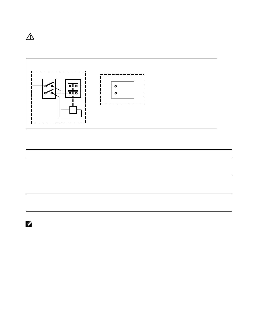
CAUTION:
If the UPS does not have an automatic protection device against current backfeed, install an
external isolating device. After the device is installed, you must add a warning label with the following
wording or the equivalent on the external AC contactor: RISK OF VOLTAGE BACKFEED. Isolate the UPS before
operating on this circuit, then check for hazardous voltage between all terminals.
External Distribution Panel
UPS
Legend
QT
B
Coil Remote Switch
Q
Magneto-Thermal Input
L/L1
L/L1
Main Switch
N/L2
N/L2
T
AC Contactor
N/L2
Neutral/L2
L/L1
L1 Line Input
B
The following table lists backfeed protection devices (AC contactors) that can be used as an external
isolating device for backfeed protection. Only use AC contactors listed in the table.
Manufacturer Type Rating
ABB France (E12527)
220–240 Vac, 105A
A75-30
25 HP at 208V, 30HP at
240V
Tianshui 213 Electrical Apparatus Co., Ltd.
220–240 Vac, 68A
(E203071)
GSC1(CJX4-d)-6511
25 HP
(alternative)
Tianshui 213 Electrical Apparatus Co., Ltd.
220–240 Vac, 80A
(E203071)
GSC1(CJX4-d)-8011
30 HP
(alternative)
NOTE:
Although the UPS does not contain anti-backfeed (ABF) relays, some backfeed protection is provided.
For example, if some components are damaged in battery mode, the output voltage may feed back to the input.
In this case, a current transformer (CT) is used to detect the bypass current feedback voltage. If a current
backfeed fault condition is detected, the UPS will terminate the inverter output to avoid the personal injury.
20
|
Installation and Startup
