Dell POWEREDGE M1000E: Figure 1-2. Installing the Pass-Through Module 2. Attach a Fiber Optic Cable (Optional)
Figure 1-2. Installing the Pass-Through Module 2. Attach a Fiber Optic Cable (Optional): Dell POWEREDGE M1000E
Table of contents
- Notes, Cautions, and Warnings
- 1. Install the Pass-Through Module Figure 1-1. Removing the Pin Cover
- Figure 1-2. Installing the Pass-Through Module 2. Attach a Fiber Optic Cable (Optional)
- 3. View Status LEDs Table 1-1. Port Status LED – Emulex Yellow LED Green LED State
- Table 1-1. Port Status LED – Emulex (continued) Yellow LED Green LED State Table 1-2. Port Status LED – QLogic Yellow LED Green LED State Table 1-3. Pass-Through Module Status LEDs Green LED Yellow/Blue LED State
- 4. Install Drivers 5. Having Problems? 6. Laser Safety
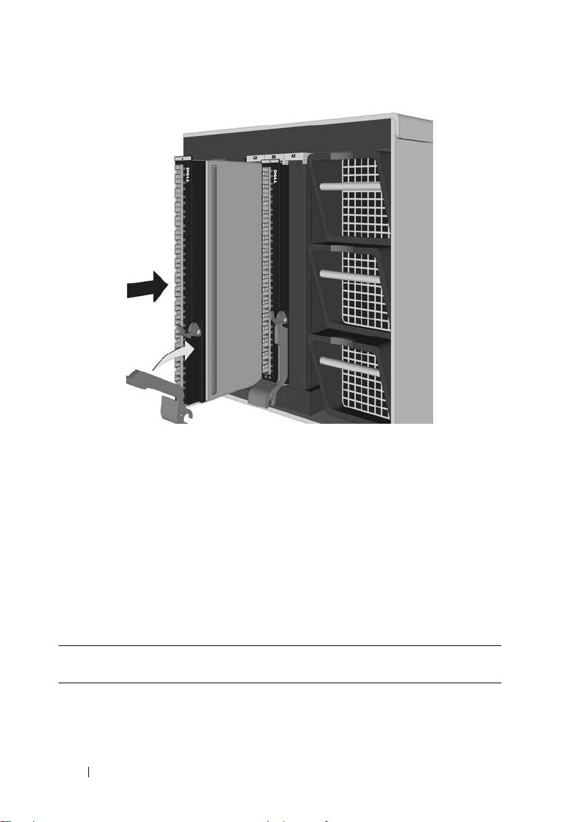
Figure 1-2. Installing the Pass-Through Module
5
Rotate the latching arm upward until it is flush against the front panel,
and the top of the arm is seated in the latch, as shown in Figure 1-2,
Installing the Pass-Through Module.
2. Attach a Fiber Optic Cable
(Optional)
Install a fiber optic cable between the pass-through module and the target
device. With short-wave lasers, use multimode fiber optic cable that adheres
to the following specifications.
Fiber Optic Cable Maximum Length Minimum
Connector
Length
62.5/125 μm (multimode) 200
150 meters at 2.125 Gb/s
.5 meters LC
MHz*km bandwidth cable
70 meters at 4.25 Gb/s
21 meters at 8.5 Gb/s
6 FC8PT Pass-Through Module
Top 10 manuals
100.00
NZXT HALE90 1000W99.99
Samsung SM-R38099.97
AEG BSB 18C99.97
Dell 2700W99.97
Smeg KSEC70X99.96
Beurer HDE 4099.96
Pyramida KH 50 v.299.96
MSI CSM-H81M-P3299.96
AEG HR 562799.95
Melissa 640-048