Asus P5V-VM DH – страница 3
Инструкция к Материнской Плате Asus P5V-VM DH
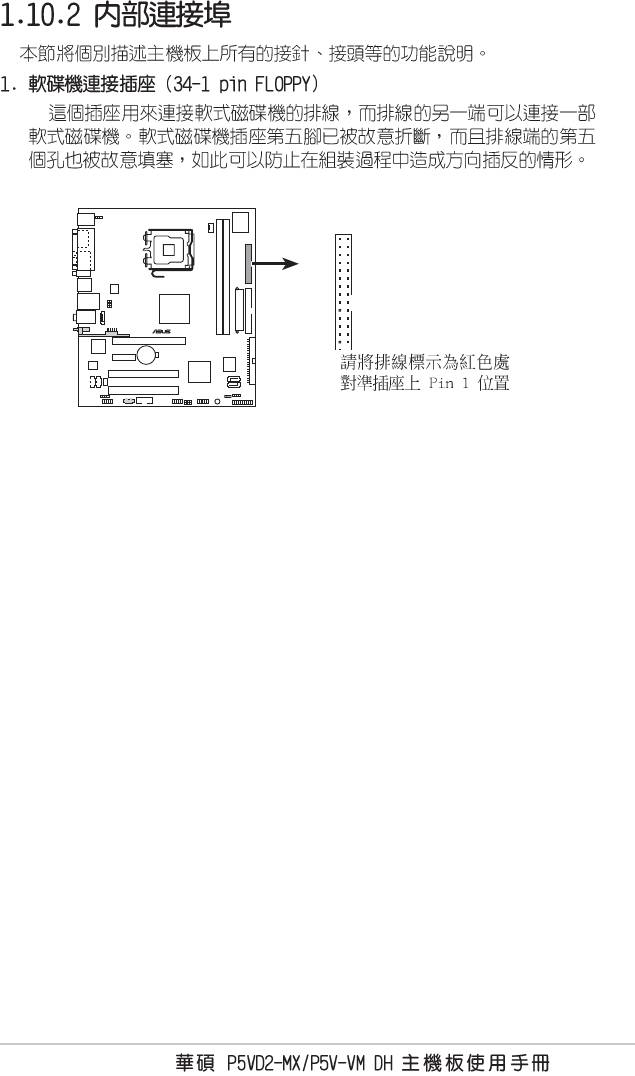
FLOPPY
®
PIN 1
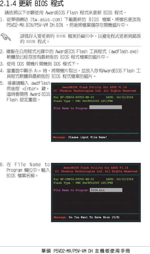
NOTE: Orient the red markings on
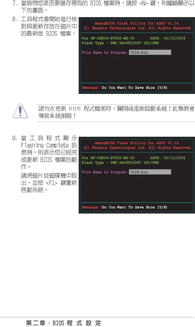
the floppy ribbon cable to PIN 1.
Floppy disk drive connector
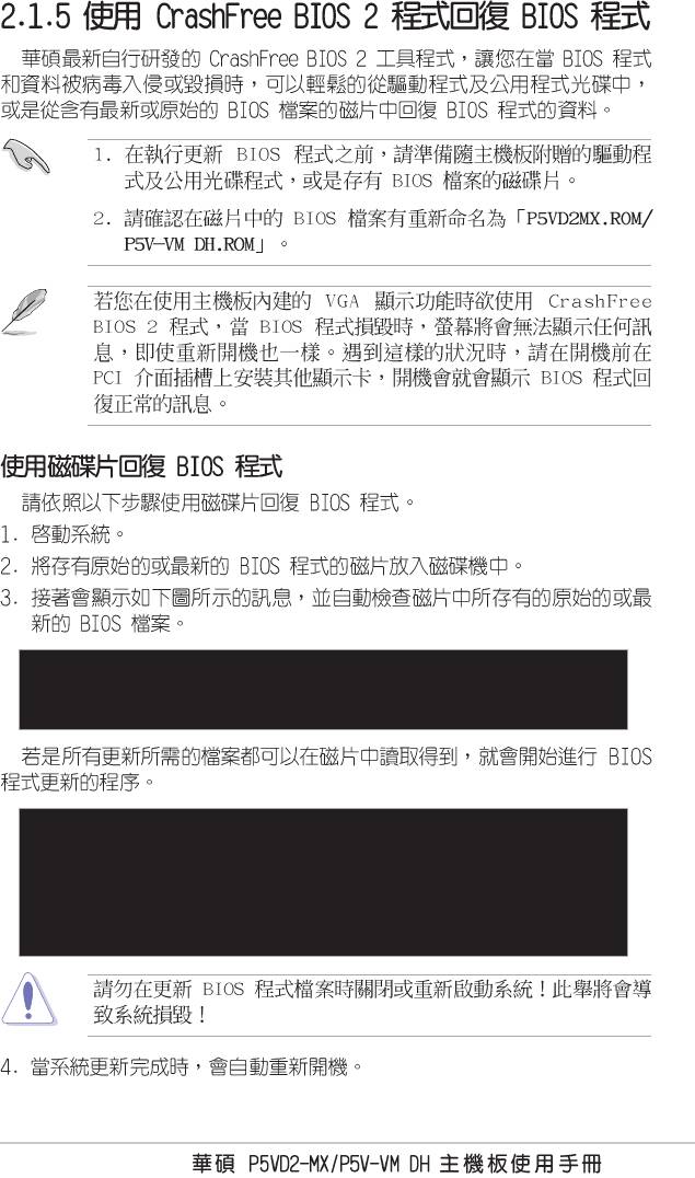
1-27
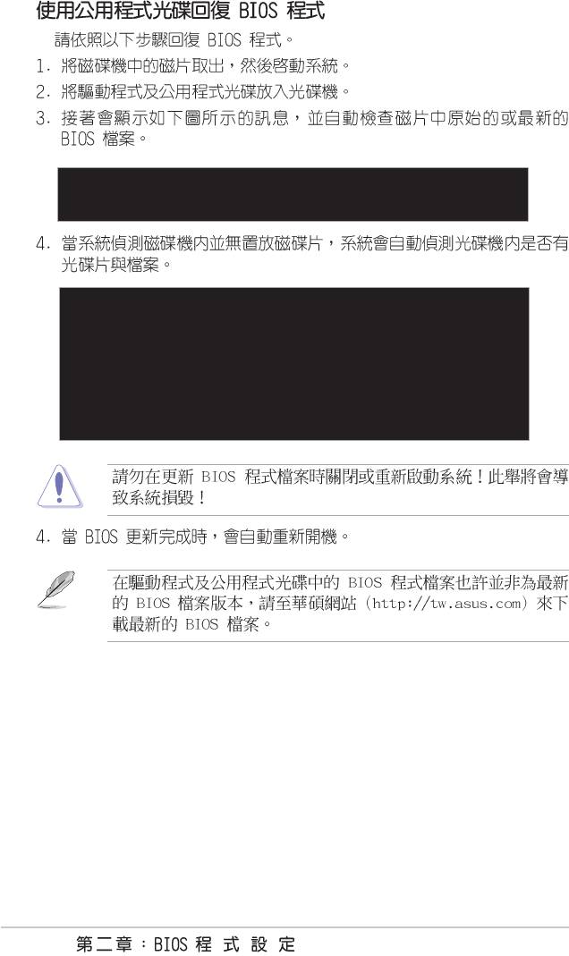
•
•
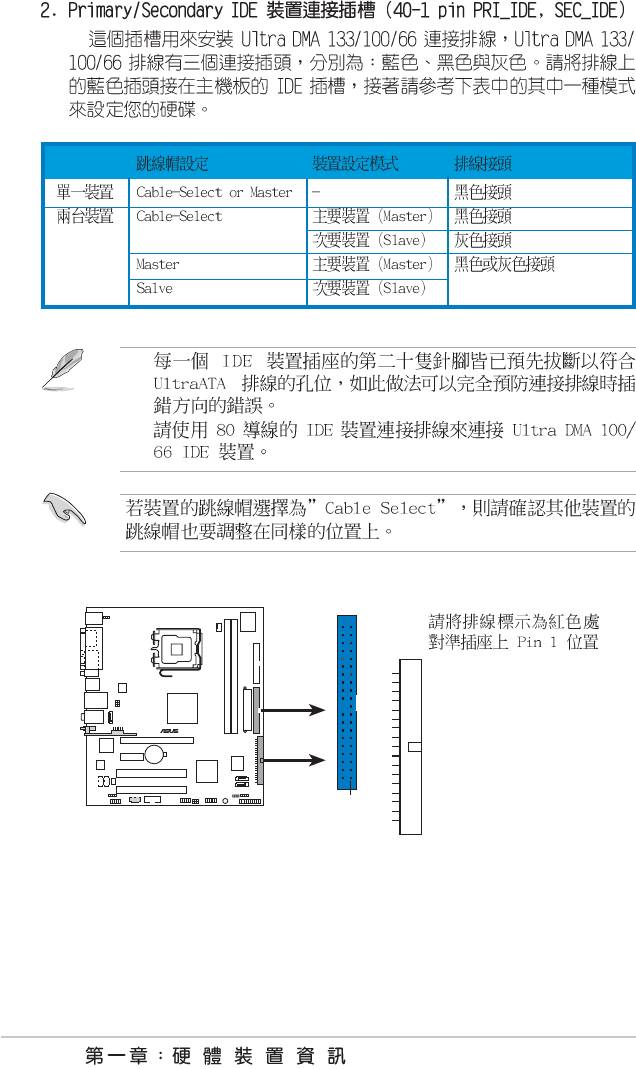
NOTE: Orient the red markings
(usually zigzag) on the IDE
ribbon cable to PIN 1.
®
PRI_IDE
PIN 1
IDE connectors
SEC_IDE
1-28
RSATA_RXN2
RSATA_RXP2
RSATA_TXN2
RSATA_TXP2
GND
GND
GND
®
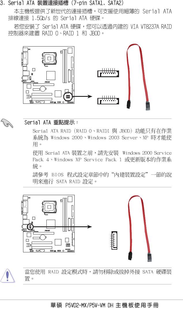
SATA2
RSATA_RXN1
RSATA_RXP1
RSATA_TXN1
RSATA_TXP1
GND
GND
GND
SATA1
SATA connectors
•
•
•
SATA_A
®
GND
RSATA_TXP2
RSATA_TXN2
GND
RSATA_RXP2
RSATA_RXN2
GND
SATA RAID connector
1-29
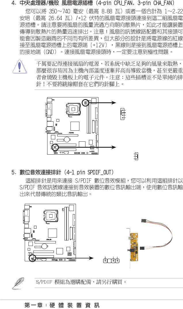
CPU_FAN
GND
CPU FAN PWR
CPU FAN IN
CPU FAN PWM
®
CHA_FAN
Rotation
+12V
Fan connectors
GND
SPDIF_OUT
SPDIFOUT
®
GND
+5V
Digital audio connector
1-30
•
•
•
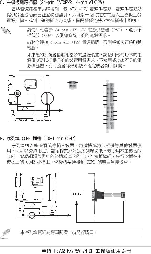
EATXPWR
ATX12V
GND
GND
+3 Volts
+3 Volts
+12V DC
+12V DC
-12 Volts
+3 Volts
Ground
Ground
PSON#
+5 Volts
Ground
Ground
®
Ground
+5 Volts
Ground
Ground
-5 Volts
Power OK
+5 Volts
+5V Standby
+5 Volts
+12 Volts
+5 Volts
+12 Volts
ATX power connectors
Ground
+3 Volts
COM2
®
PIN 1
COM port connector
1-31
CD(Black)
®
AUX(White)
Right Audio Channel
Ground
Ground
Left Audio Channel
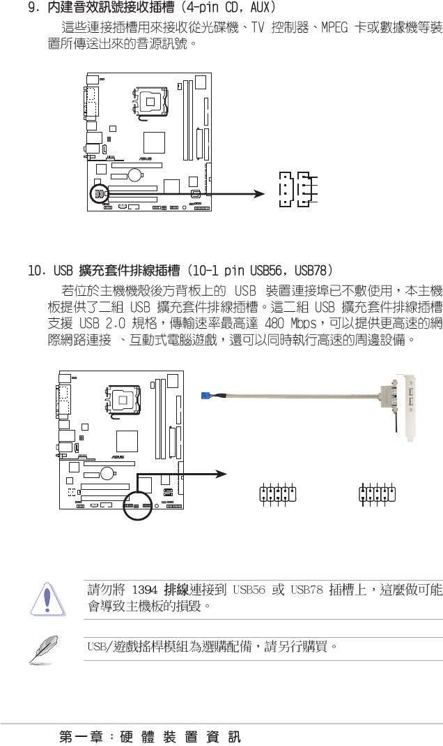
Internal audio connectors
®
USB+5V
USB_P6-
USB_P6+
GND
NC
USB+5V
USB_P8-
USB_P8+
GND
NC
USB56
USB78
1
1
GND
GND
USB 2.0 connectors
USB+5V
USB_P5-
USB+5V
USB_P5+
USB_P7-
USB_P7+
1-32
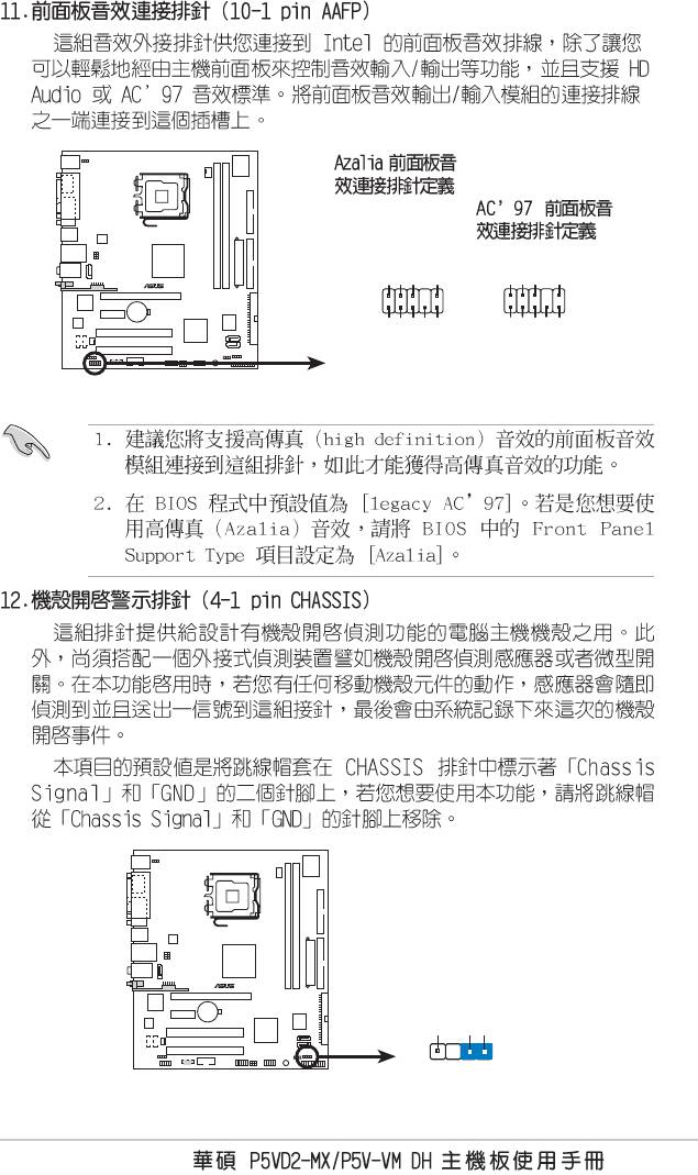
Legacy AC’97-compliant
pin definition
GND
PRESENCE#
SENSE1_RETUR
SENSE2_RETUR
AGND
NC
NC
NC
®
AAFP
NC
MIC2_L
MIC2_R
PORT1 L
PORT1 R
PORT2 R
PORT2 L
Line out_R
Line out_L
SENSE_SEND
Analog front panel connector
CHASSIS
®
+5VSB_MB
Chassis Signal
GND
(Default)
Chassis intrusion connector
1-33
MP3IN
®
Left Audio Channel
Ground
Ground
Right Audio Channel
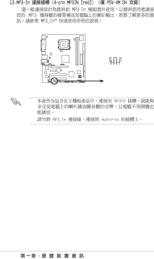
MP3 connector
•
•
1-34
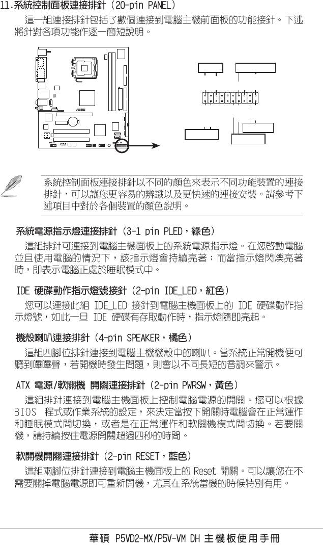
PLED
SPEAKER
PLED+
PLED-
+5V
Ground
Ground
Speaker
PANEL
®
PWR
Ground
Reset
Ground
IDE_LED+
IDE_LED-
RESET
IDE_LED
PWRSW
*
Requires an ATX power supply.
System panel connector
•
•
•
•
•
1-35
1-36
2-1
2-2
2-3
2-4
2-5
Insert Disk then press Enter or ESC to continue POST
2-6
2-7
2-8
Bad BIOS checksum. Starting BIOS recovery...
Checking for floppy...
Bad BIOS checksum. Starting BIOS recovery...
Checking for floppy...
Floppy found!
Reading file “P5VD2MX.ROM”. Completed.
Start flashing...
2-9
Bad BIOS checksum. Starting BIOS recovery...
Checking for floppy...
Bad BIOS checksum. Starting BIOS recovery...
Checking for floppy...
Floppy not found!
Checking for CD-ROM...
CD-ROM found!
Reading file “P5VD2MX.ROM”. Completed.
Start flashing...
