Asus M2N68 SE: 1.6 Central Processing Unit (CPU)
1.6 Central Processing Unit (CPU): Asus M2N68 SE
1.5.4 Layout contents
Connectors/Jumpers/Slots Page
1. ATX power connectors (24-pin EATXPWR, 8-pin ATX12V) 1-23
2. DDR2 DIMM slots
1-10
3. CPU fan connector (4-pin CPU_FAN)
1-8
4. MCP68PVNT Serial ATA connectors [red] (7-pin SATA1-4)
1-21
5. Clear RTC RAM (3-pin CLRTC)
1-17
6. IDE connector (40-1 pin PRI_EIDE)
1-20
7. System panel connector (10-1 pin PANEL)
1-24
8. USB connectors (10-1 pin USB56, USB78, USB910)
1-22
9. SPEAKER connector (4-pin)
1-19
10. Floppy disk drive connector (34-1 pin FLOPPY) 1-19
11. Digital audio connector (4-1 pin SPDIF_OUT) 1-24
12. Optical drive audio connector (4-pin CD)
1-20
13. Front panel audio connector (10-1 pin AAFP)
1-22
14. AMD CPU 940-pin Socket
1-7
1.6 Central Processing Unit (CPU)
®
The motherboard comes with an AM2+ / AM2 socket designed for AMD
AM2+ / AM2
Phenom™ FX / Phenom / Athlon™ / Sempron™ processor.
The AM2/AM2+ socket has a different pinout from the 940-pin socket designed for the
AMD Opteron™ processor. Ensure that you use a CPU that is designed for the AM2/AM2+
socket. The CPU ts in only one correct orientation. DO NOT force the CPU into the socket
to prevent bending the connectors on the socket and damaging the CPU!
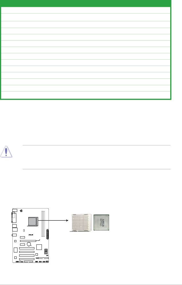
1.6.1 Installing the CPU
To install a CPU:
1. Locate the CPU socket on the motherboard.
M2N68 SE
M2N68 SE CPU socket 940
Chapter 1: Product introduction 1-7
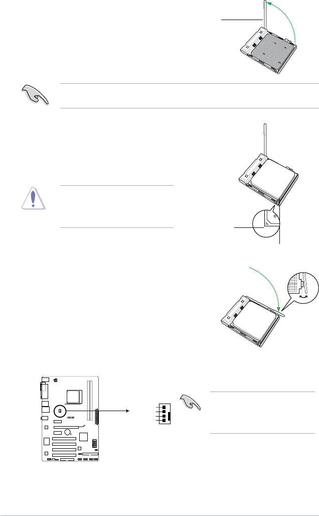
2. Unlock the socket by pressing the lever sideways, then lift it
up to a 90°-100° angle.
Socket lever
Ensure that the socket lever is lifted up to 90°-100° angle, otherwise the CPU will not t in
completely.
3. Position the CPU above the socket such that the CPU
corner with the gold triangle matches the socket corner
with a small triangle.
4. Carefully insert the CPU into the socket until it ts in place.
The CPU ts only in one correct
orientation. DO NOT force the CPU into
the socket to prevent bending the pins
and damaging the CPU!
Small triangle
Gold triangle
5. When the CPU is in place, push down the socket
lever to secure the CPU. The lever clicks on the side
tab to indicate that it is locked.
6. Install a CPU heatsink and fan following the
instructions that came with the heatsink package.
You can also refer to section 1.6.2 Installing
heatsink and fan for instructions.
7. Connect the CPU fan cable to the CPU_FAN connector on the motherboard.
CPU_FAN
CPU FAN PWM
CPU FAN IN
CPU FAN PWR
M2N68 SE
GND
M2N68 SE CPU fan connector
Do not forget to connect the CPU
fan connector! Hardware monitoring
errors can occur if you fail to plug
this connector.
1-8 ASUS M2N68 SE
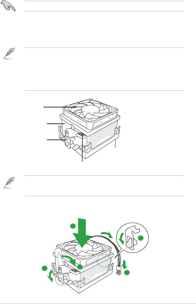
1.6.2 Installing the heatsink and fan
Make sure that you use only AMD-certied heatsink and fan assembly.
Follow these steps to install the CPU heatsink and fan.
1. Place the heatsink on top of the installed CPU, making sure that the heatsink ts
properly on the retention module base.
• The retention module base is already installed on the motherboard upon purchase.
• You do not have to remove the retention module base when installing the CPU or
installing other motherboard components.
• If you purchased a separate CPU heatsink and fan assembly, make sure that a Thermal
Interface Material is properly applied to the CPU heatsink or CPU before you install the
heatsink and fan assembly.
CPU Fan
CPU Heatsink
Retention bracket
Retention Module Base
Retention bracket lock
Your boxed CPU heatsink and fan assembly should come with installation instructions for
the CPU, heatsink, and the retention mechanism. If the instructions in this section do not
match the CPU documentation, follow the latter.
2. Attach one end of the retention bracket to the retention module base.
1
2
4
3
5
Chapter 1: Product introduction 1-9
Оглавление
- Contents
- Contents
- Contents
- Notices
- Safety information
- M2N68 SE specications summary
- 1.1 Welcome!
- 1.4 Before you proceed
- 1.5 Motherboard overview
- 1.6 Central Processing Unit (CPU)
- 1.7 System memory
- 1.8 Expansion slots
- 1.9 Jumpers
- 1.10 Connectors
- 1.11 Software support
- 2.1 Managing and updating your BIOS
- 2.2 BIOS setup program
- 2.3 Main menu
- 2.4 Advanced menu
- 2.5 Power menu
- 2.6 Boot menu
- 2.7 Tools menu
- 2.8 Exit menu
