Asus M2N68 SE: 1.10 Connectors
1.10 Connectors: Asus M2N68 SE
1.10 Connectors
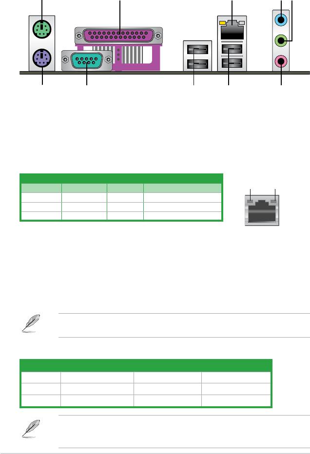
1.10.1 Rear panel connectors
1
2
4 53
10
9
68 7
1. PS/2 Mouse port. This port is for a PS/2 mouse.
2. Parallel port.
This 25-pin port connects a parallel printer, a scanner, or other devices.
3. LAN (RJ-45) port.
This port allows Gigabit connection to a Local Area Network (LAN)
through a network hub.
LAN port LED indications
ACT/LINK
SPEED
Activity/Link LED Speed LED
LED
LED
Status Description Status Description
OFF No link OFF 10 Mbps connection
ORANGE Linked ORANGE 100 Mbps connection
BLINKING Data activity GREEN 1 Gbps connection
LAN port
4. Line In port (light blue). This port connects the tape, CD, DVD player, or other audio
sources.
5. Line Out port (lime).
This port connects a headphone or a speaker. In 4-channel, 6-
channel, and 8-channel conguration, the function of this port becomes Front Speaker
Out.
6. Microphone port (pink).
This port connects a microphone.
Refer to the audio conguration table on next page for the function of the audio ports in 2,
4, or 6-channel conguration.
Audio 2, 4, 6-channel conguration
Port Headset 2-channel 4-channel 6-channel
Light Blue Line In Rear Speaker Out Rear Speaker Out
Lime Line Out Front Speaker Out Front Speaker Out
Pink Mic In Mic In Bass/Center
Ensure that the audio device of Sound playback is Realtek High Denition Audio (the
name may be different based on the OS). Go to Start > Control Panel > Sounds and
Audio Devices > Sound Playback to congure the setting.
1-18 ASUS M2N68 SE
7. USB 2.0 ports 1 and 2. These two 4-pin Universal Serial Bus (USB) ports are
available for connecting USB 2.0 devices.
8. USB 2.0 ports 3 and 4.
These two 4-pin Universal Serial Bus (USB) ports are
available for connecting USB 2.0 devices.
9. COM port.
This 9-pin COM1 port is for pointing devices or other serial devices.
10. PS/2 keyboard port. This port is for a PS/2 keyboard.
1.10.2 Internal connectors
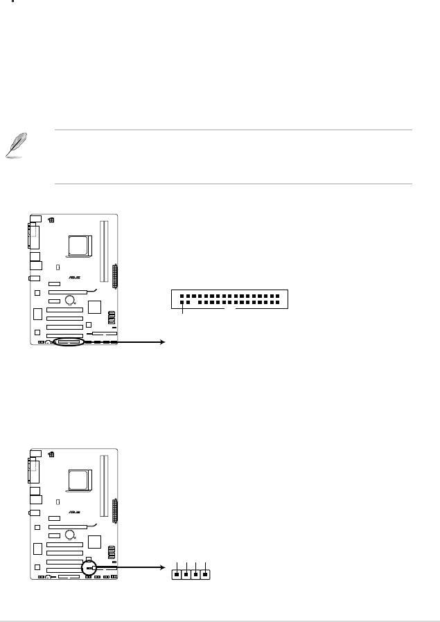
1. Floppy disk drive connector (34-1 pin FLOPPY)
This connector is for a Floppy Disk Drive (FDD) signal cable. Insert one end of the
cable to this connector, then connect the other end to the signal connector at the back
of the oppy disk drive.
• Pin 5 on the connector is removed to prevent incorrect cable connection when using an
FDD cable with a covered Pin 5.
• The Floppy Disk Drive singal cable is purchased separately.
M2N68 SE
FLOPPY
PIN1
NOTE:Orient the red markings
on the floppy ribbon cable to PIN 1.
M2N68 SE Floppy disk drive connector
2. Speaker connector (4- pin SPEAKER)
This 4-pin connector is for the chassis-mounted system warning speaker. The speaker
allows you to hear system beeps and warnings.
SPEAKER
M2N68 SE
+5V
GND
GND
Speaker Out
PIN 1
M2N68 SE Speaker Out Connector
Chapter 1: Product introduction 1-19
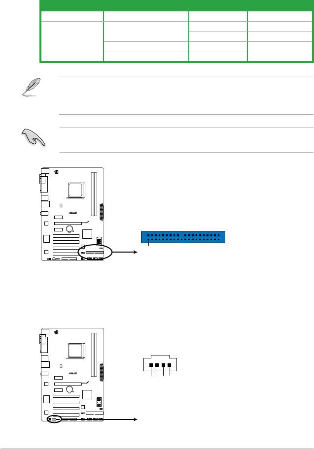
3. IDE connector (40-1 pin PRI_IDE)
The onboard IDE connector is for Ultra DMA 133/100/66 signal cable. There are
three connectors on each Ultra DMA 133 / 100 / 66 signal cable: blue, black, and gray.
Connect the blue connector to the motherboard’s IDE connector, then select one of the
following modes to congure your device(s).
Drive jumper setting Mode of device(s) Cable connector
Single device Cable-Select or Master - Black
Master Black
Cable-Select
Slave Gray
Two devices
Master Master
Black or gray
Slave Slave
• Pin 20 on the IDE connector is removed to match the covered hole on the Ultra DMA
cable connector. This prevents incorrect insertion when you connect the IDE cable.
• Use the 80-conductor IDE cable for Ultra DMA 133/100/66 IDE devices.
If any device jumper is set as “Cable-Select”, ensure that all other device jumpers have the
same setting.
M2N68 SE
PRI_IDE
PIN1
NOTE:Orient the red markings
on the IDE ribbon cable to PIN 1.
M2N68 SE IDE connector
4. Optical drive audio in connector (4-pin CD)
This connector allows you to receive stereo audio input from sound sources such as a
CD-ROM, TV tuner, or MPEG card.
CD
M2N68 SE
GND
GND
Left Audio Channel
Right Audio Channel
M2N68 SE Internal audio connector
1-20 ASUS M2N68 SE
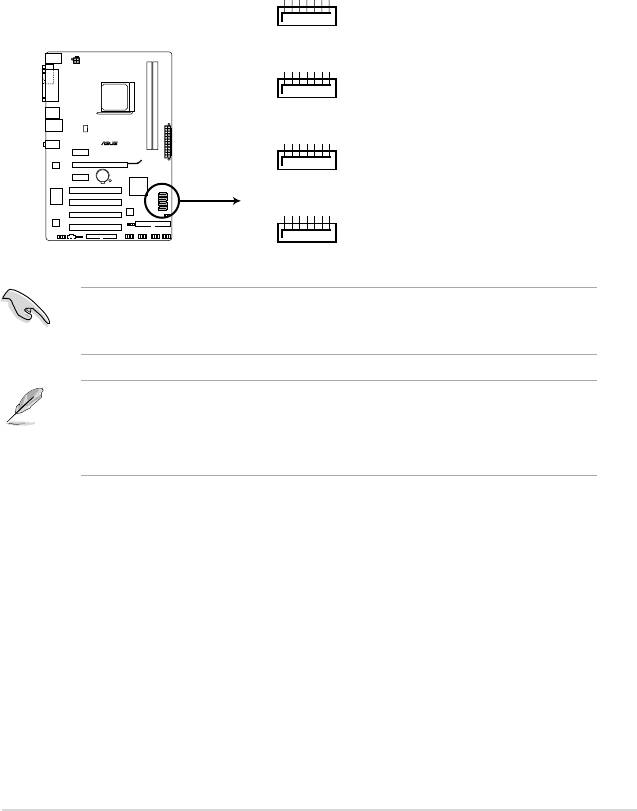
5. Serial ATA connectors (7-pin SATA1, SATA2, SATA3, SATA4)
These connectors are for the Serial ATA signal cables for Serial ATA 3Gb/s hard disk
and optical disk drives. The Serial ATA 3Gb/s is backward compatible with Serial ATA
1.5Gb/s specication. The data transfer rate of the Serial ATA 3Gb/s is faster than the
standard parallel ATA with 133 MB/s (Ultra DMA133).
If you install Serial ATA hard disk drives, you can create a RAID 0,
RAID 1, RAID 0+1, RAID 5, and JBOD conguration through the onboard controller.
GND
RSATA_RXN4
RSATA_RXP4
GND
RSATA_TXN4
RSATA_TXP4
GND
SATA4
GND
RSATA_RXN3
RSATA_RXP3
GND
RSATA_TXN3
RSATA_TXP3
GND
SATA3
GND
RSATA_RXN2
RSATA_RXP2
GND
RSATA_TXN2
RSATA_TXP2
GND
M2N68 SE
SATA2
GND
RSATA_RXN1
RSATA_RXP1
GND
RSATA_TXN1
RSATA_TXP1
GND
SATA1
M2N68 SE SATA connectors
Important note on Serial ATA
®
Install the Windows
XP Service Pack 1 before using Serial ATA.
• For detailed instructions on how to congure RAID 0, RAID 1, and RAID 0+1, RAID 5,
and JBOD, refer to the RAID manual in the support DVD.
• If you intend to create a Serial ATA RAID set using these connectors, set the
SATA
Mode select item in the BIOS to [RAID Mode]. See page 2-10 for details.
Chapter 1: Product introduction 1-21
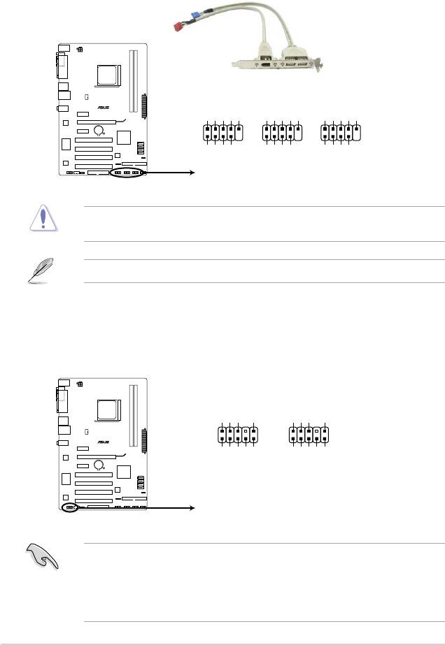
6. USB connectors (10-1 pin USB56, USB 78, USB910)
These connectors are for USB 2.0 ports. Connect the USB module cable to any of
these connectors, then install the module to a slot opening at the back of the system
chassis. These USB connectors comply with USB 2.0 specication that supports up to
480 Mbps connection speed.
USB56 USB78
USB910
M2N68 SE
USB+5V
USB_P6-
USB_P6+
GND
NC
USB+5V
USB_P8-
USB_P8+
GND
NC
USB+5V
USB_P10-
USB_P10+
GND
NC
PIN 1
PIN 1
PIN 1
GND
GND
GND
USB+5V
USB_P5-
USB+5V
USB_P5+
USB_P7-
USB+5V
USB_P7+
USB_P9-
USB_P9+
M2N68 SE USB2.0 connectors
Never connect a 1394 cable to the USB connectors. Doing so will damage the
motherboard!
The USB 2.0 module is purchased separately.
7. Front panel audio connector (10-1 pin AAFP)
This connector is for a chassis-mounted front panel audio I/O module that supports
either High Denition Audio or AC`97 audio standard. Connect one end of the front
panel audio I/O module cable to this connector.
GND
PRESENCE#
SENSE1_RETUR
SENSE2_RETUR
AGND
NC
NC
NC
AAFP
PIN 1
PIN 1
M2N68 SE
NC
MIC2
PORT1 L
PORT1 R
PORT2 R
PORT1 L
MICPWR
Line out_R
Line out_L
SENSE_SEND
HD-audio-compliant
Legacy AC’97
pin definition
compliant definition
M2N68 SE Analog front panel connector
• We recommend that you connect a high-denition front panel audio module to this
connector to avail of the motherboard high-denition audio capability.
• By default, this connector is set to
[HD Audio]. If you want to connect a High Denition
front panel audio module to this connector, set the Front Panel Select item in the BIOS
to [HD Audio]. See section “2.4.3 Chipset” for details.
1-22 ASUS M2N68 SE
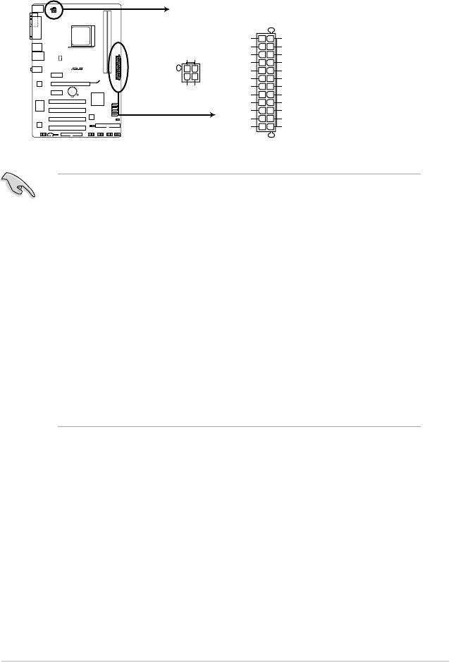
8. ATX power connectors (24-pin EATXPWR, 4-pin ATX12V)
These connectors are for an ATX power supply. The plugs from the power supply are
designed to t these connectors in only one orientation. Find the proper orientation and
push down rmly until the connectors completely t.
ATX12V
EATXPWR
+3 Volts
GND
+12 Volts
+5 Volts
+12V DC
+12V DC
+12 Volts
+5 Volts
+5V Standby
+5 Volts
Power OK
-5 Volts
M2N68 SE
PIN 1
GND
GND
+5 Volts
GND
GND
GND
GND
GND
+5 Volts
PSON#
GND
GND
+3 Volts
-12 Volts
+3 Volts
+3 Volts
PIN 1
M2N68 SE ATX power connectors
•
We recommend that you use an ATX 12 V Specication 2.0-compliant power supply
unit (PSU) with a minimum of 300 W power rating. This PSU type has 24-pin and 4-pin
power plugs.
•
If you intend to use a PSU with 20-pin and 4-pin power plugs, make sure that the 20-pin
power plug can provide at least 15 A on +12 V and that the PSU has a minimum power
rating of 300 W. The system may become unstable or may not boot up if the power is
inadequate.
•
Do not forget to connect the 4-pin ATX +12 V power plug; otherwise, the system will not
boot up.
• We recommend that you use a PSU with higher power output when conguring a
system with more power-consuming devices. The system may become unstable or may
not boot up if the power is inadequate.
• If you are uncertain about the minimum power supply requirement for your system,
refer to the Recommended Power Supply Wattage Calculator at http://support.asus.
com/PowerSupplyCalculator/PSCalculator.aspx?SLanguage=en-us for details.
•
You must install a PSU with a higher power rating if you intend to install additional
devices.
Chapter 1: Product introduction 1-23
10. Digital audio connector (4-1 pin SPDIF_OUT)
This connector is for an additional Sony/Philips Digital Interface (S/PDIF) port(s).
M2N68 SE
+5V
SPDIFOUT
GND
SPDIF_OUT
M2N68 SE Digital audio connector
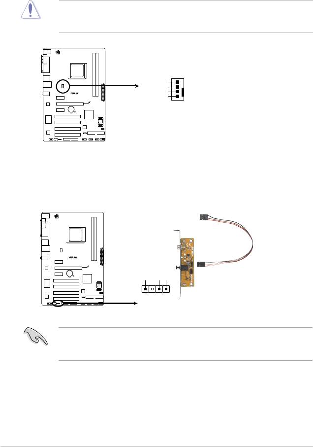
9. CPU fan connector (4-pin CPU_FAN)
The fan connector supports cooling fans of 350 mA~2000 mA (24 W max.) or a total
of 1 A~7 A (84 W max.) at +12V. Connect the fan cable to the fan connector on the
motherboard, making sure that the black wire of each cable matches the ground pin of
the connector.
Do not forget to connect the fan cables to the fan connectors. Insufcient air ow inside the
system may damage the motherboard components. These are not jumpers! Do not place
jumper caps on the fan connectors!
Ensure that the audio device of Sound playback is Realtek High Denition Audio (the
name may be different based on the OS). Go to Start > Control Panel > Sounds and
Audio Devices > Sound Playback to congure the setting.
CPU_FAN
CPU FAN PWM
CPU FAN IN
CPU FAN PWR
M2N68 SE
GND
M2N68 SE CPU fan connector
1-24 ASUS M2N68 SE
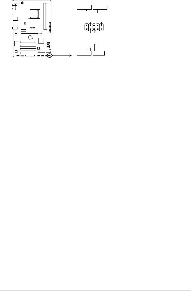
11. System panel connector (10-1 pin F_PANEL)
This connector supports several chassis-mounted functions.
PWR LED
PWR BTN
PLED+
PLED-
PWR
GND
M2N68 SE
F_PANEL
PIN 1
Reset
Ground
IDE_LED+
IDE_LED-
+HD_LED RESET
M2N68 SE System panel connector
• System power LED (2-pin PWRLED)
This 2-pin connector is for the system power LED. Connect the chassis power LED
cable to this connector. The system power LED lights up when you turn on the system
power, and blinks when the system is in sleep mode.
•
Hard disk drive activity LED (2-pin HDLED)
This 2-pin connector is for the HDD Activity LED. Connect the HDD Activity LED cable
to this connector. The IDE LED lights up or ashes when data is read from or written to
the HDD.
•
Power/Soft-off button (2-pin PWRBTN)
This 2-pin connector is for the system power button. Pressing the power button turns
the system ON or puts the system in SLEEP or SOFT-OFF mode depending on the
BIOS settings. Pressing the power switch for more than four seconds while the system
is ON turns the system OFF.
•
Reset button (2-pin RESET)
This 2-pin connector is for the chassis-mounted reset button for system reboot without
turning off the system power.
Chapter 1: Product introduction 1-25
Оглавление
- Contents
- Contents
- Contents
- Notices
- Safety information
- M2N68 SE specications summary
- 1.1 Welcome!
- 1.4 Before you proceed
- 1.5 Motherboard overview
- 1.6 Central Processing Unit (CPU)
- 1.7 System memory
- 1.8 Expansion slots
- 1.9 Jumpers
- 1.10 Connectors
- 1.11 Software support
- 2.1 Managing and updating your BIOS
- 2.2 BIOS setup program
- 2.3 Main menu
- 2.4 Advanced menu
- 2.5 Power menu
- 2.6 Boot menu
- 2.7 Tools menu
- 2.8 Exit menu
