Asus A8N-E: 2 Knowing the Parts
2 Knowing the Parts: Asus A8N-E
2 Knowing the Parts
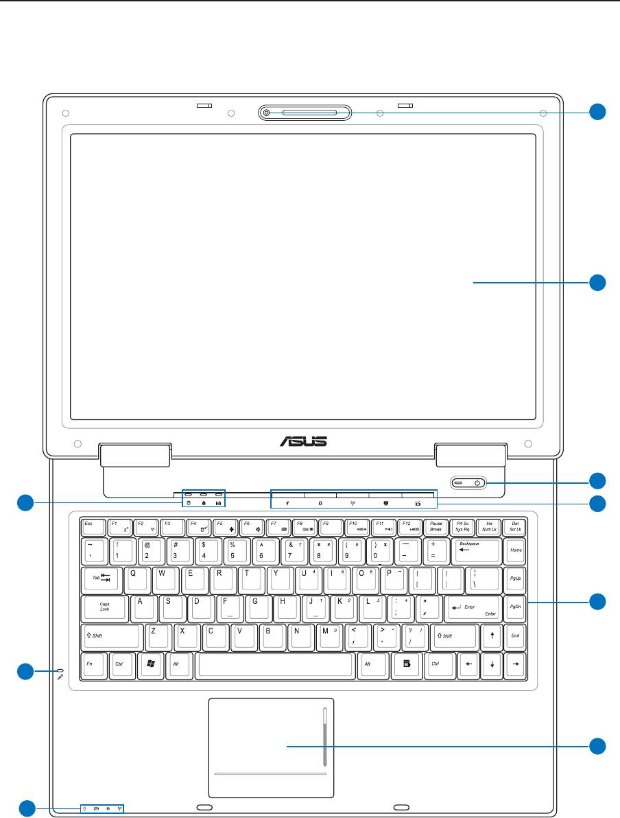
Top Side
Refer to the diagram below to identify the components on this side of the Notebook PC.
12
1
2
3
4
5
6
9
8
7
Knowing the Parts 2
13
2
3
4
5
6
7
8
1
9
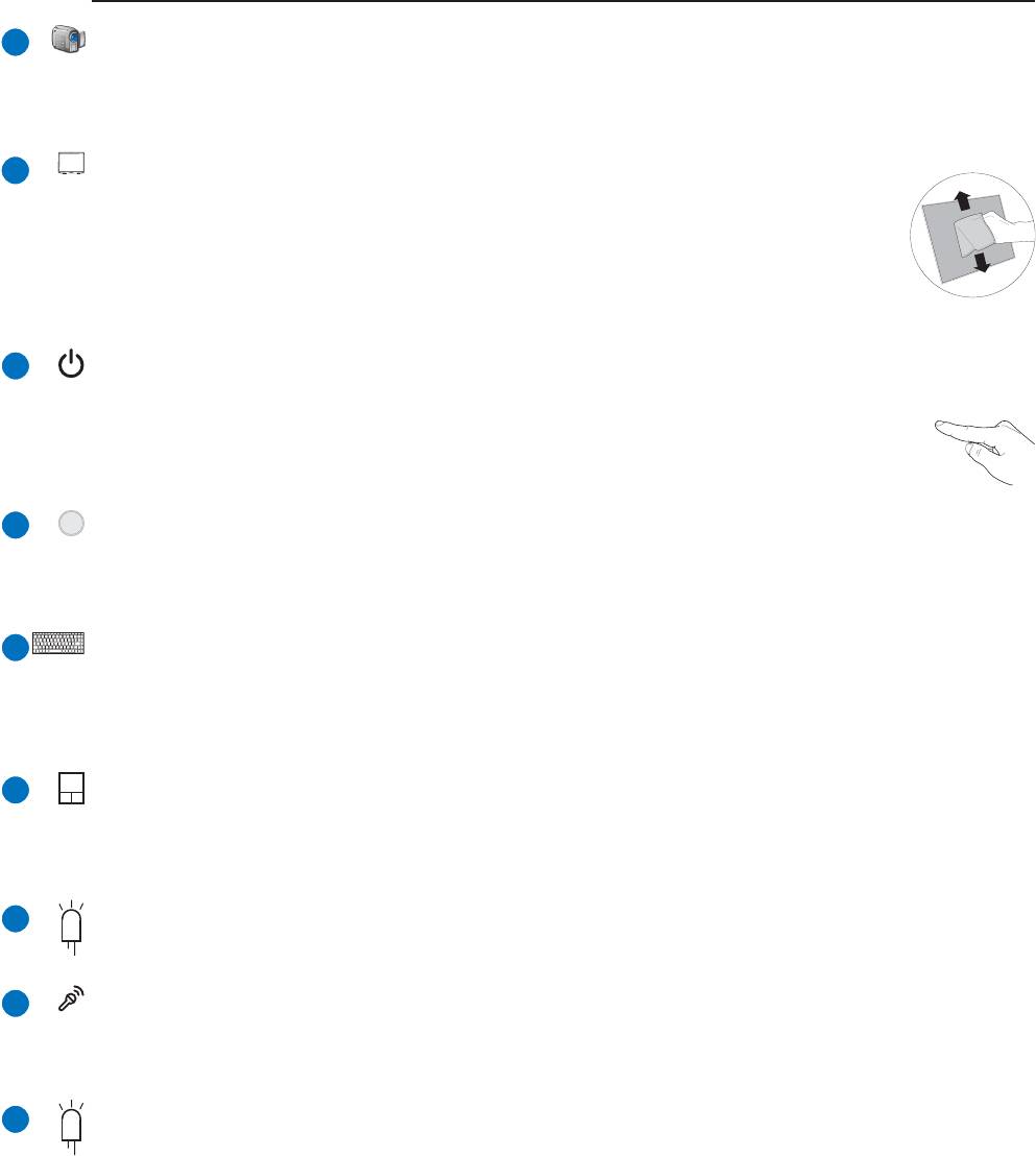
Camera (on selected models)
The built-in camera allows picture taking or video recording. Can be used with video conferencing and
other interactive applications.
Display Panel
The display panel functions the same as a desktop monitor. The Notebook PC uses an
active matrix TFT LCD, which provides excellent viewing like that of desktop monitors.
Unlike desktop monitors, the LCD panel does not produce any radiation or flickering,
so it is easier on the eyes. Use a soft cloth without chemical liquids (use plain water if
necessary) to clean the display panel.
Power Switch
The power switch allows powering ON and OFF the Notebook PC and recovering from STD. Use the
switch once to turn ON and once to turn OFF the Notebook PC. In Windows XP, this button
can also be used to safely turn OFF the Notebook PC. The power switch only works when
the display panel is opened.
Instant Keys
Instant keys allow you to launch frequently used applications with one push of a button. Details are
described in section 3.
Keyboard
The keyboard provides full-sized keys with comfortable travel (depth at which the keys can be depressed)
and palm rest for both hands. Two Windows™ function keys are provided to help ease navigation in the
Windows™ operating system.
Touchpad and Buttons
The touchpad with its buttons is a pointing device that provides the same functions as a desktop mouse.
A software-controlled scrolling function is available after setting up the included touchpad utility to
allow easy Windows or web navigation.
Status Indicators (front)
Status indicator details are described in section 3.
Microphone (Built-in)
The built-in mono microphone can be used for video conferencing, voice narrations, or simple audio
recordings.
Status Indicators (top)
Status indicator details are described in section 3.
2 Knowing the Parts
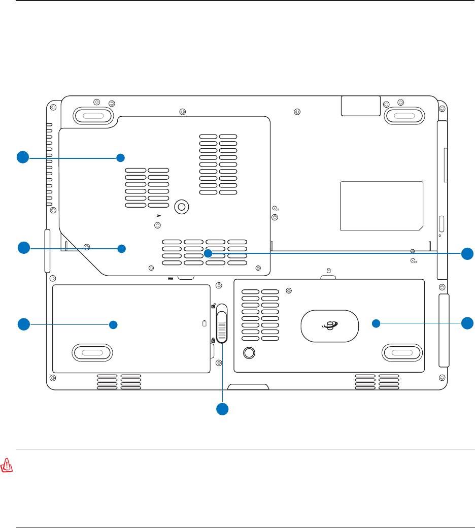
Bottom Side
Refer to the diagram below to identify the components on this side of the Notebook PC.
6
K
5
1
4
2
3
WARNING! The bottom of the Notebook PC can get very hot. Be careful when han-
dling the Notebook PC while it is in operation or recently been in operation. High
temperatures are normal during charging or operation. Do not use on soft surfaces
such as beds or sofas which may block the vents. DO NOT PUT THE NOTEBOOK PC
ON YOUR LAP OR OTHER PARTS OF THE BODY TO AVOID INJURY FROM THE HEAT.
14
Knowing the Parts 2
15
2
3
4
5
1
6
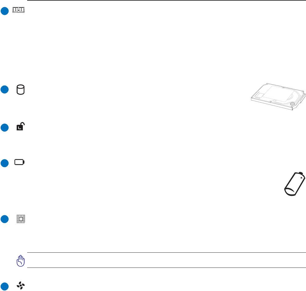
Memory (RAM) Compartment
The memory compartment provides expansion capabilities for additional memory. Additional memory
will increase application performance by decreasing hard disk access. The BIOS automatically detects
the amount of memory in the system and configures CMOS accordingly during the POST (Power-On-
Self-Test) process. There is no hardware or software (including BIOS) setup required after the memory
is installed. Visit an authorized service center or retailer for information on memory upgrades for your
Notebook PC. Only purchase expansion modules from authorized retailers of this Notebook PC to
ensure maximum compatibility and reliability.
Hard Disk Drive Compartment
The hard disk drive is secured in a compartment. Hard disk drive upgrades are to
be done by authorized service centers or dealers only.
Battery Lock - Spring
The spring battery lock is used to keep the battery pack secured. When the battery pack is inserted, it will
automatically lock. To remove the battery pack, this spring lock must be held in the unlocked position.
Battery Pack
The battery pack is automatically charged when connected to an AC power source and maintains
power to the Notebook PC when AC power is not connected. This allows use when moving
temporarily between locations. Battery time varies by usage and by the specifications for this
Notebook PC. The battery pack cannot be disassembled and must be purchased as a single unit.
Central Processor Unit (CPU)
Some Notebook PC models feature a socketed-processor design to allow upgrading to faster processors
in the future. Some models feature a ULV design for compactness and may not be upgraded. Visit an
authorized service center or retailer for information on upgrades.
WARNING! End-user removal of the CPU or hard disk drive will void the warranty.
Cooling Fan
The cooling fan turns ON or OFF depending on temperature threshold settings.
2 Knowing the Parts
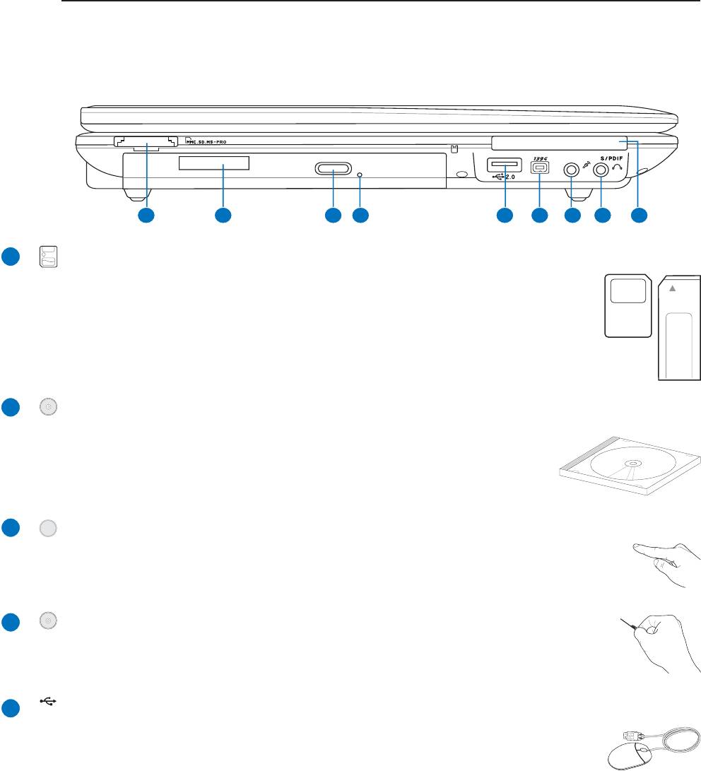
Left Side
Refer to the diagram below to identify the components on this side of the Notebook PC.
1 2 43 5 76 8 9
Optical Drive
The Notebook PC comes in various models with different optical drives. The
Notebook PC’s optical drive may support compact discs (CD) and/or digital
video discs (DVD) and may have recordable (R) or re-writable (RW)
capabilities. See the marketing specifications for details on each model.
16
2
3
4
5
1
Optical Drive Electronic Eject
The optical drive eject has an electronic eject button for opening the tray. You can also eject
the optical drive tray through any software player or by right clicking the optical drive in
Windows™ “My Computer.”
Optical Drive Emergency Eject
The emergency eject is used to eject the optical drive tray in case the electronic eject
does not work. Do not use the emergency eject in place of the electronic eject.
2.0
Flash Memory Slot
Normally a separate card reader must be purchased separately in order to use memory
cards from devices such as digital cameras, MP3 players, mobile phones, and PDAs.
This Notebook PC has a built-in memory card reader that can read many flash memory
cards as specified later in this manual. The built-in memory card reader is not only
convenient, but also faster than most other forms of memory card readers because it
utilizes the high-bandwidth PCI bus.
USB Port (2.0/1.1)
The Universal Serial Bus is compatible with USB 2.0 or USB 1.1 devices such as
keyboards, pointing devices, cameras, hard disk drives, printers, and scanners connected
in a series up to 12Mbits/sec (USB 1.1) and 480Mbits/sec (USB 2.0). USB allows
many devices to run simultaneously on a single computer, with peripherals such as USB keyboards and
some newer monitors acting as additional plug-in sites or hubs. USB supports hot-swapping of devices
so that most peripherals can be connected or disconnected without restarting the computer.
Knowing the Parts 2
17
6
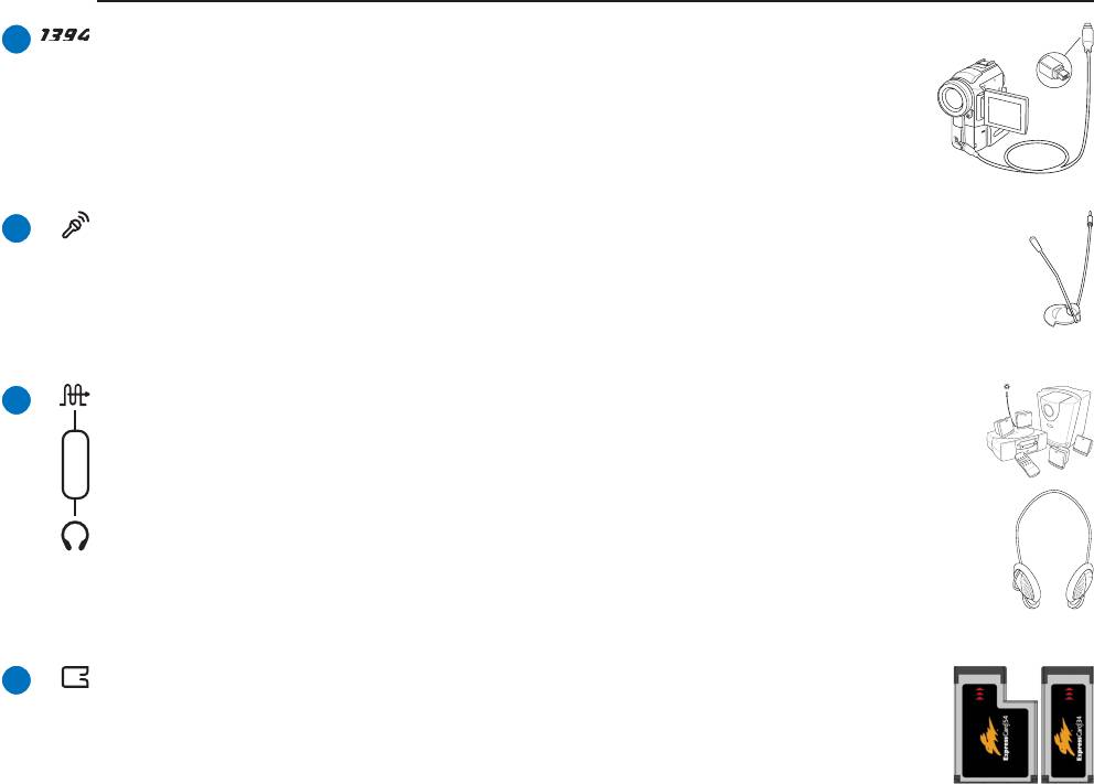
Microphone Input Jack (Mic In)
The mono microphone jack (1/8 inch) can be used to connect an external microphone or
output signals from audio devices. Using this jack automatically disables the built-in
microphone. Use this feature for video conferencing, voice narrations, or simple audio
recordings.
SPDIF Output Jack
This jack provides connection to SPDIF (Sony/Philips Digital Interface) compliant devices
for digital audio output. Use this feature to turn the Notebook PC into a hi-fi home
Combo
entertainment system.
Headphone Output Jack
The stereo headphone jack (1/8 inch) is used to connect the Notebook PC’s audio out signal to
amplified speakers or headphones. Using this jack automatically disables the built-in speakers.
7
8
9
IEEE1394 Port
IEEE1394 is a high speed serial bus like SCSI but has simple connections and hot-
plugging capabilities like USB. The interface IEEE1394 has a bandwidth of 100-
400 Mbits/sec and can handle up to 63 units on the same bus. IEEE1394 is also used
in high-end digital equipment and should be marked “DV” for Digital Video port.
ExpressCard Slot
One 26pin Express card slot is available to support one ExpressCard/34mm or one
ExpressCard/54mm expansion card. This new interface is faster by using a serial bus
supporting USB 2.0 and PCI Express instead of the slower parallel bus used in the PC
card slot. (Not compatible with previous PCMCIA cards.)
2 Knowing the Parts
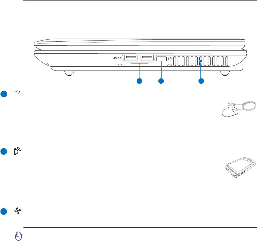
Right Side
Refer to the diagram below to identify the components on this side of the Notebook PC.
1 2 3
18
2.0
USB Port (2.0/1.1)
The Universal Serial Bus is compatible with USB 2.0 or USB 1.1 devices such as
keyboards, pointing devices, cameras, hard disk drives, printers, and scanners connected
in a series up to 12Mbits/sec (USB 1.1) and 480Mbits/sec (USB 2.0). USB allows
many devices to run simultaneously on a single computer, with peripherals such as USB keyboards and
some newer monitors acting as additional plug-in sites or hubs. USB supports hot-swapping of devices
so that most peripherals can be connected or disconnected without restarting the computer.
2
3
1
Infrared Port (IrDA) (on selected models)
The infrared (IrDA) communication port allows convenient wireless data communication
with infrared-equipped devices or computers. This allows easy wireless synchronization
with PDAs or mobile phones and even wireless printing to printers. If your office supports
IrDA networking, you can have wireless connection to a network anywhere provided there
is a direct line of sight to an IrDA node. Small offices can use IrDA technology to share a printer between
several closely placed Notebook PCs and even send files to each other without a network.
Air Vents
The air vents allow cool air to enter and warm air to exit the Notebook PC.
IMPORTANT! Make sure that paper, books, clothing, cables, or other objects do not
block any of the air vents or else overheating of the Notebook PC may occur.
Knowing the Parts 2
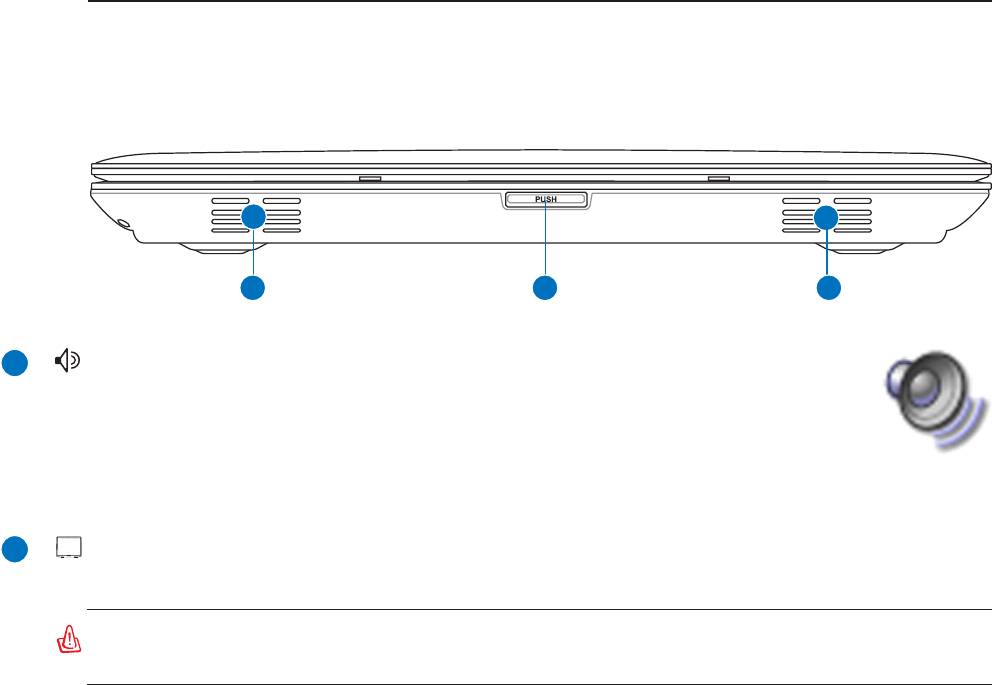
Front Side
Refer to the diagram below to identify the components on the front side of the Notebook PC.
1 2 1
19
2
1
Audio Speakers
The built-in stereo speaker system allows you to hear audio without additional
attachments. The multimedia sound system features an integrated digital audio controller
that produces rich, vibrant sound (results improved with external stereo headphones or
speakers). Audio features are software controlled.
Display Panel Button
Press the display panel button to open the display panel.
WARNING! When opening, do not force the display panel down to the table or else
the hinges may break! Never lift the Notebook PC by the display panel!
2 Knowing the Parts
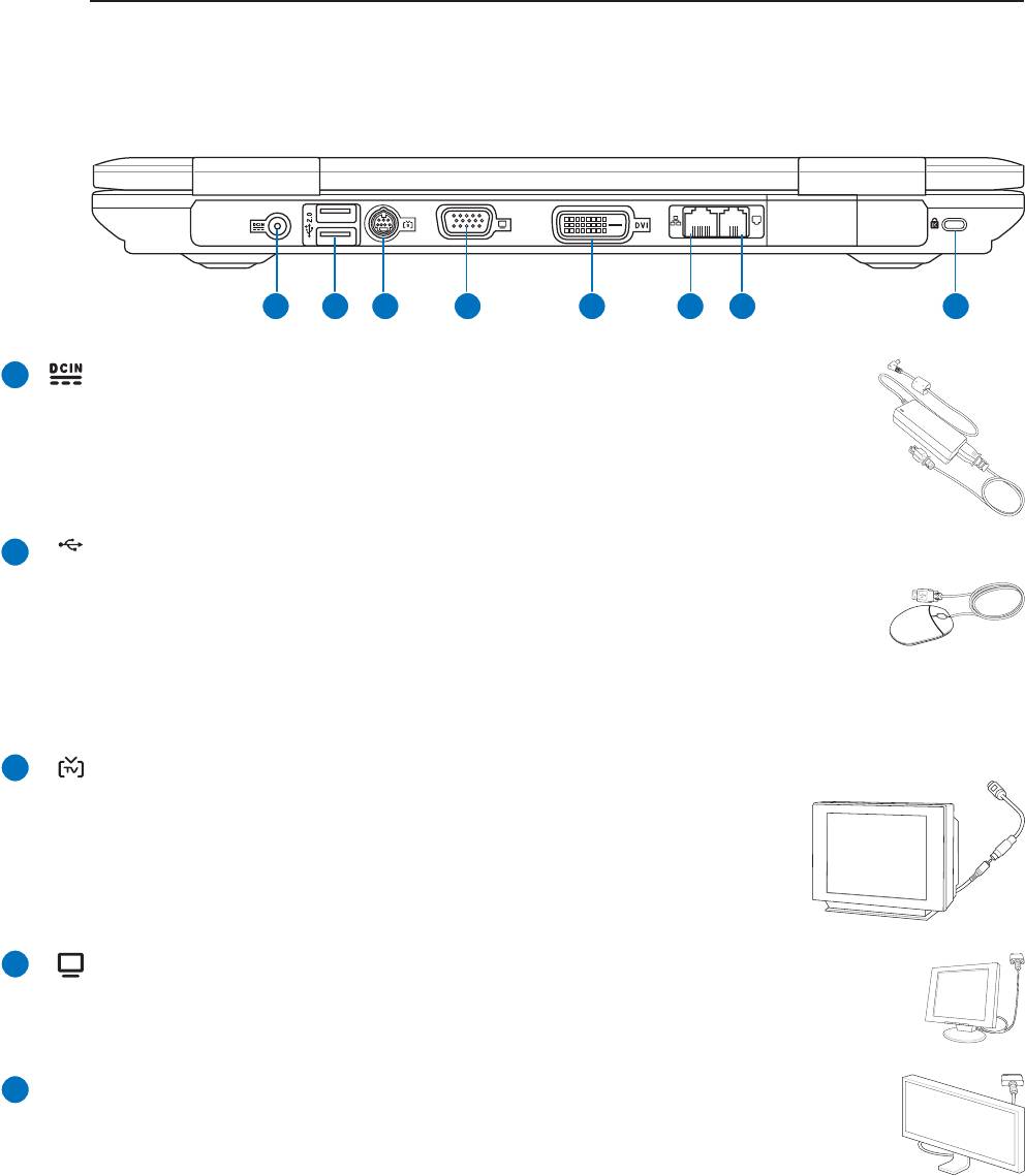
Rear Side
Refer to the diagram below to identify the components on this side of the Notebook PC.
20
2
3
1
2.0
USB Port (2.0/1.1)
The Universal Serial Bus is compatible with USB 2.0 or USB 1.1 devices such as
keyboards, pointing devices, cameras, hard disk drives, printers, and scanners connected
in a series up to 12Mbits/sec (USB 1.1) and 480Mbits/sec (USB 2.0). USB allows
many devices to run simultaneously on a single computer, with peripherals such as USB keyboards and
some newer monitors acting as additional plug-in sites or hubs. USB supports hot-swapping of devices
so that most peripherals can be connected or disconnected without restarting the computer.
TV-Out Port
The TV-Out port is an S-Video connector that allows routing the Notebook
PC’s display to a television or video projection device. You can choose
between simultaneouly or single display. Use an S-Video cable (not provided)
for high quality displays or use the provided RCA to S-Video adapter for
standard video devices. This port supports both NTSC and PAL formats.
Display (Monitor) Output
The 15-pin D-sub monitor port supports a standard VGA-compatible device such as a
monitor or projector to allow viewing on a larger external display.
DVI-D
Display (DVI-D) Output (on selected models)
The Digital Video Interface port is designed to maximize video graphics output to flat
panel LCD monitors or other DVI-compliant device.
4
5
1 2 43 5 76 8
Power (DC) Input
The supplied power adapter converts AC power to DC power for use with this jack. Power
supplied through this jack supplies power to the ASUS Notebook PC and charges the internal
battery pack. To prevent damage to the ASUS Notebook PC and battery pack, always use the
supplied power adapter. CAUTION: MAY BECOME WARM TO HOT WHEN IN USE.
BE SURE NOT TO COVER THE ADAPTER AND KEEP IT AWAY FROM YOUR BODY.
Knowing the Parts 2
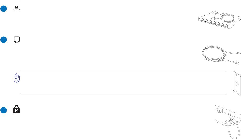
LAN Port
The RJ-45 LAN port with eight pins is larger than the RJ-11 modem port and
supports a standard Ethernet cable for connection to a local network. The built-in
connector allows convenient use without additional adapters.
Modem Port
The RJ-11 modem port with two pins is smaller than the RJ-45 LAN port and supports
a standard telephone cable. The internal modem supports up to 56K V.90 transfers.
The built-in connector allows convenient use without additional adapters.
IMPORTANT! The built-in modem does not support the voltage used in digital
phone systems. Do not connect the modem port to a digital phone system or else
damage will occur to the Notebook PC.
21
6
7
8
®
Kensington
Lock Port
®
®
The Kensington
lock port allows the Notebook PC to be secured using Kensington
compatible Notebook PC security products. These security products usually include a
metal cable and lock that prevent the Notebook PC to be removed from a fixed object.
Some security products may also include a motion detector to sound an alarm when moved.

2 Knowing the Parts
22
3. Getting Started
Using AC Power
Using Battery Power
Powering ON the Notebook PC
Checking Battery Power
Restarting or Rebooting
Powering OFF the Notebook PC
Special Keyboard Functions
Switches and Status Indicators
23
