Dell XPS 14Z (L412z): инструкция
Раздел: Компьютерная техника, комплектующие, аксессуары
Тип: Ноутбук
Инструкция к Ноутбуку Dell XPS 14Z (L412z)
Оглавление

book.book Page 1 Thursday, May 3, 2012 3:09 PM
Dell™ XPS™ 14z
Owner’s Manual
Computer model: L412z Regulatory model: P24G series Regulatory type: P24G001

book.book Page 2 Thursday, May 3, 2012 3:09 PM
Notes, Cautions, and Warnings
NOTE: A NOTE indicates important information that helps you make better use of
your computer.
CAUTION: A CAUTION indicates potential damage to hardware or loss of data if
instructions are not followed.
WARNING: A WARNING indicates a potential for property damage, personal
injury, or death.
____________________
Information in this document is subject to change without notice.
© 2011 Dell Inc. All rights reserved.
Reproduction of these materials in any manner whatsoever without the written permission of Dell Inc.
is strictly forbidden.
™
Trademarks used in this text: Dell™, the DELL logo, and XPS
are trademarks of Dell Inc.;
®
®
Microsoft
, Windows
and the Windows start button logo
are either trademarks or registered
®
trademarks of Microsoft corporation in the United States and/or other countries; Bluetooth
is a
registered trademark owned by Bluetooth SIG, Inc. and is used by Dell under license.
Other trademarks and trade names may be used in this document to refer to either the entities claiming
the marks and names or their products. Dell Inc. disclaims any proprietary interest in trademarks and
trade names other than its own.
Regulatory model: P24G series Regulatory type: P24G001
2011 - 09 Rev. A00

book.book Page 3 Thursday, May 3, 2012 3:09 PM
Contents
1 Before You Begin. . . . . . . . . . . . . . . . . . . . 7
Recommended Tools. . . . . . . . . . . . . . . . . . . . 7
Turning Off Your Computer
. . . . . . . . . . . . . . . . . 7
Before Working Inside Your Computer . . . . . . . . . . 8
2 Base Cover . . . . . . . . . . . . . . . . . . . . . . . 11
Removing the Base Cover . . . . . . . . . . . . . . . . 11
Replacing the Base Cover
. . . . . . . . . . . . . . . . 12
3 Battery . . . . . . . . . . . . . . . . . . . . . . . . . . . 15
Removing the Battery . . . . . . . . . . . . . . . . . . 15
Replacing the Battery . . . . . . . . . . . . . . . . . . 16
4 Memory Module(s) . . . . . . . . . . . . . . . . . 17
Removing the Memory Module(s) . . . . . . . . . . . . 17
Replacing the Memory Module(s)
. . . . . . . . . . . . 18
Contents 3

book.book Page 4 Thursday, May 3, 2012 3:09 PM
5 Wireless Mini-Card . . . . . . . . . . . . . . . . 21
Removing the Mini-Card . . . . . . . . . . . . . . . . . 21
Replacing the Mini-Card
. . . . . . . . . . . . . . . . . 23
6 Hard Drive . . . . . . . . . . . . . . . . . . . . . . . 25
Removing the Hard Drive . . . . . . . . . . . . . . . . 25
Replacing the Hard Drive
. . . . . . . . . . . . . . . . 28
7 Coin-Cell Battery . . . . . . . . . . . . . . . . . . 29
Removing the Coin-Cell Battery . . . . . . . . . . . . . 29
Replacing the Coin-Cell Battery . . . . . . . . . . . . . 30
8 Optical Drive . . . . . . . . . . . . . . . . . . . . . 31
Removing the Optical Drive . . . . . . . . . . . . . . . 31
Replacing the Optical Drive
. . . . . . . . . . . . . . . 33
9 Hall-Sensor Board . . . . . . . . . . . . . . . . . 35
Removing the Hall-Sensor Board . . . . . . . . . . . . 35
Replacing the Hall-Sensor Board . . . . . . . . . . . . 37
4 Contents

book.book Page 5 Thursday, May 3, 2012 3:09 PM
10 Display-Converter Board. . . . . . . . . . . . . 39
Removing the Display-Converter Board. . . . . . . . . 39
Replacing the Display-Converter Board
. . . . . . . . 40
11 Heat Sink and Fan . . . . . . . . . . . . . . . . . . 41
Removing the Heat Sink and Fan . . . . . . . . . . . . 41
Replacing the Heat Sink and Fan
. . . . . . . . . . . . 42
12 System Board . . . . . . . . . . . . . . . . . . . . . 45
Removing the System Board . . . . . . . . . . . . . . . 45
Replacing the System Board. . . . . . . . . . . . . . . 48
Entering the Service Tag in the BIOS
. . . . . . . . . . 49
13 Power-Button Board . . . . . . . . . . . . . . . . 51
Removing the Power-Button Board . . . . . . . . . . . 51
Replacing the Power-Button Board
. . . . . . . . . . . 52
14 Keyboard . . . . . . . . . . . . . . . . . . . . . . . . . 53
Removing the Keyboard Bracket . . . . . . . . . . . . 53
Replacing the Keyboard Bracket
. . . . . . . . . . . . 57
Removing the Keyboard
. . . . . . . . . . . . . . . . . 58
Replacing the Keyboard
. . . . . . . . . . . . . . . . . 59
Contents 5

book.book Page 6 Thursday, May 3, 2012 3:09 PM
15 Speakers . . . . . . . . . . . . . . . . . . . . . . . . 61
Removing the Speakers . . . . . . . . . . . . . . . . . 61
Replacing the Speakers
. . . . . . . . . . . . . . . . . 64
16 Display . . . . . . . . . . . . . . . . . . . . . . . . . . 65
Display Hinge Covers . . . . . . . . . . . . . . . . . . 65
Removing the Display Hinge Covers . . . . . . . . 65
Replacing the Display Hinge Covers . . . . . . . . 67
Display Assembly . . . . . . . . . . . . . . . . . . . . 68
Removing the Display Assembly . . . . . . . . . . 68
Replacing the Display Assembly . . . . . . . . . . 69
17 Palm-Rest Assembly . . . . . . . . . . . . . . . 71
Removing the Palm-Rest Assembly . . . . . . . . . . . 71
Replacing the Palm-Rest Assembly
. . . . . . . . . . . 72
18 Flashing the BIOS . . . . . . . . . . . . . . . . . 73
6 Contents

book.book Page 7 Thursday, May 3, 2012 3:09 PM
1
Before You Begin
This manual provides procedures for removing and installing the components
in your computer. Unless otherwise noted, each procedure assumes that the
following conditions exist:
• You have performed the steps in "Turning Off Your Computer" on page 7
and "Before Working Inside Your Computer" on page 8.
• You have read the safety information that shipped with your computer
.
• A component can be replaced or—if purchased separately—installed by
performing the removal procedure in reverse order.
Recommended Tools
The procedures in this document may require the following tools:
• Small flat-blade screwdriver
•Phillips screwdriver
• BIOS executable update program available at
support.dell.com
Turning Off Your Computer
CAUTION: To avoid losing data, save and close all open files and exit all open
programs before you turn off your computer.
1
Save and close all open files and exit all open programs.
2
To shut down the operating system, click
Start
and then click
Shut
Down
.
3
Ensure that the computer is turned off. If your computer did not
automatically turn off when you shut down the operating system, press
and hold the power button until the computer turns off.
Before You Begin 7

book.book Page 8 Thursday, May 3, 2012 3:09 PM
Before Working Inside Your Computer
Use the following safety guidelines to help protect your computer from
potential damage and to help to ensure your own personal safety.
WARNING: Before working inside your computer, read the safety information
that shipped with your computer. For additional safety best practices
information, see the Regulatory Compliance Homepage at
www.dell.com/regulatory_compliance.
CAUTION: To avoid electrostatic discharge, ground yourself by using a wrist
grounding strap or by periodically touching an unpainted metal surface (such as
a connector on your computer).
CAUTION: Handle components and cards with care. Do not touch the components
or contacts on a card. Hold a card by its edges or by its metal mounting bracket.
Hold a component such as a processor by its edges, not by its pins.
CAUTION: Only a certified service technician should perform repairs on your
computer. Damage due to servicing that is not authorized by Dell is not covered by
your warranty.
CAUTION: When you disconnect a cable, pull on its connector or on its pull-tab,
not on the cable itself. Some cables have connectors with locking tabs; if you are
disconnecting this type of cable, press in on the locking tabs before you
disconnect the cable. As you pull connectors apart, keep them evenly aligned to
avoid bending any connector pins. Also, before you connect a cable, ensure that
both connectors are correctly oriented and aligned.
CAUTION: To avoid damaging the computer, perform the following steps before
you begin working inside the computer.
1
Ensure that the work surface is flat and clean to prevent the computer
cover from being scratched.
2
Turn off your computer (see "Turning Off Your Computer" on page 7) and
all attached devices.
CAUTION: To disconnect a network cable, first unplug the cable from your
computer and then unplug the cable from the network device.
3
Disconnect all telephone or network cables from the computer.
4
Press and eject any installed cards from the Media Card Reader.
5
Disconnect your computer and all attached devices from their electrical
outlets.
8 Before You Begin

book.book Page 9 Thursday, May 3, 2012 3:09 PM
6
Disconnect all attached devices from your computer.
7
Remove the battery (see "Removing the Battery" on page 15).
8
Turn the computer top-side up, open the display, and press the power
button to ground the system board.
CAUTION: Before touching anything inside your computer, ground yourself by
touching an unpainted metal surface, such as the metal at the back of the
computer. While you work, periodically touch an unpainted metal surface to
dissipate static electricity, which could harm internal components.
Before You Begin 9

book.book Page 10 Thursday, May 3, 2012 3:09 PM
10 Before You Begin

book.book Page 11 Thursday, May 3, 2012 3:09 PM
2
Base Cover
WARNING: Before working inside your computer, read the safety information
that shipped with your computer. For additional safety best practices
information, see the Regulatory Compliance Homepage at
www.dell.com/regulatory_compliance.
CAUTION: Only a certified service technician should perform repairs on your
computer. Damage due to servicing that is not authorized by Dell is not covered by
your warranty.
CAUTION: To avoid electrostatic discharge, ground yourself by using a wrist
grounding strap or by periodically touching an unpainted metal surface (such as
a connector on your computer).
Removing the Base Cover
1
Follow the instructions in "Before You Begin" on page 7.
2
Remove the eight screws that secure the base cover to the palm-rest
assembly.
3
Starting from the rear end, use your fingertips to release the tabs on the
base cover from the slots on the palm-rest assembly.
Base Cover 11
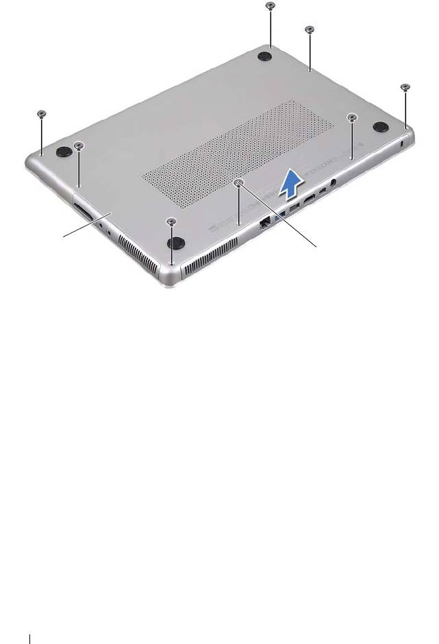
1 base cover 2 screws (8)
4
Lift the base cover off the palm-rest assembly.
Replacing the Base Cover
1
Follow the instructions in "Before You Begin" on page 7.
2
Align the tabs on the base cover with the slots on the palm-rest assembly
and snap the base cover into place.
3
Replace the eight screws that secure the base cover to the palm-rest
assembly.
12 Base Cover
1
2
book.book Page 12 Thursday, May 3, 2012 3:09 PM

book.book Page 13 Thursday, May 3, 2012 3:09 PM
Base Cover 13

book.book Page 14 Thursday, May 3, 2012 3:09 PM
14 Base Cover

book.book Page 15 Thursday, May 3, 2012 3:09 PM
3
Battery
WARNING: Before working inside your computer, read the safety information
that shipped with your computer. For additional safety best practices
information, see the Regulatory Compliance Homepage at
www.dell.com/regulatory_compliance.
CAUTION: Only a certified service technician should perform repairs on your
computer. Damage due to servicing that is not authorized by Dell is not covered by
your warranty.
CAUTION: To avoid electrostatic discharge, ground yourself by using a wrist
grounding strap or by periodically touching an unpainted metal surface (such as
a connector on your computer).
CAUTION: To avoid damage to the computer, use only the battery designed for
this particular Dell computer. Do not use batteries designed for other Dell
computers.
Removing the Battery
1
Follow the instructions in "Before You Begin" on page 7.
2
Remove the base cover (see "Removing the Base Cover" on page 11).
3
Disconnect the battery cable from the system-board connector.
4
Remove the five screws that secure the battery to the palm-rest assembly.
5
Lift the battery off the palm-rest assembly.
Battery 15
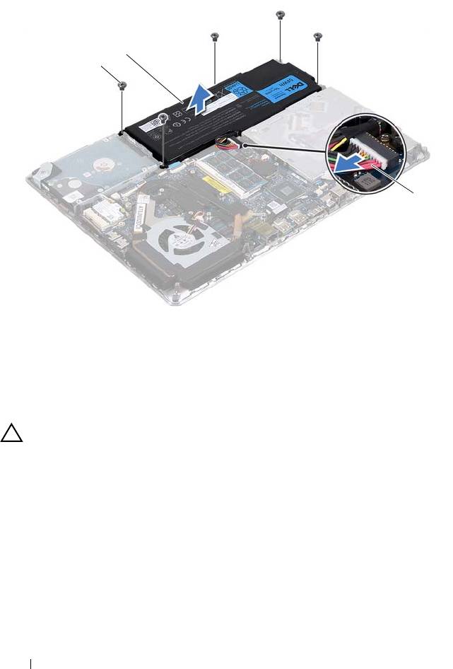
1 screws (5) 2 battery
3 battery cable
Replacing the Battery
CAUTION: To avoid damage to the computer, use only the battery designed for
this particular Dell computer.
1
Follow the instructions in "Before You Begin" on page 7.
2
Place the battery on the palm-rest assembly.
3
Replace the five screws that secure the battery to the palm-rest assembly.
4
Connect the battery cable to the system-board connector.
5
Replace the base cover (see "Replacing the Base Cover" on page 12).
16 Battery
2
1
3
book.book Page 16 Thursday, May 3, 2012 3:09 PM

book.book Page 17 Thursday, May 3, 2012 3:09 PM
4
Memory Module(s)
WARNING: Before working inside your computer, read the safety information
that shipped with your computer. For additional safety best practices
information, see the Regulatory Compliance Homepage at
www.dell.com/regulatory_compliance.
CAUTION: Only a certified service technician should perform repairs on your
computer. Damage due to servicing that is not authorized by Dell is not covered by
your warranty.
CAUTION: To avoid electrostatic discharge, ground yourself by using a wrist
grounding strap or by periodically touching an unpainted metal surface (such as
a connector on your computer).
CAUTION: To help prevent damage to the system board, remove the main battery
(see "Removing the Battery" on page 15) before working inside the computer.
You can increase your computer memory by installing memory modules on
the system board. See "Specifications" at support.dell.com/manuals for
information on the type of memory supported by your computer.
NOTE: Memory modules purchased from Dell are covered under your computer
warranty.
Your computer has two user-accessible SODIMM connectors. The primary
memory module can be accessed by removing the back cover. The secondary
memory module can be accessed by removing the system board.
Removing the Memory Module(s)
1
Follow the instructions in "Before You Begin" on page 7.
2
Remove the base cover (see "Removing the Base Cover" on page 11).
3
Remove the battery (see "Removing the Battery" on page 15).
CAUTION: To help prevent damage to the memory-module connector, do not use
tools to spread the memory module securing clips.
NOTE: To access the second memory module, remove the system board and turn it
over. To remove the system board, see "Removing the System Board" on page 45.
Memory Module(s) 17
4
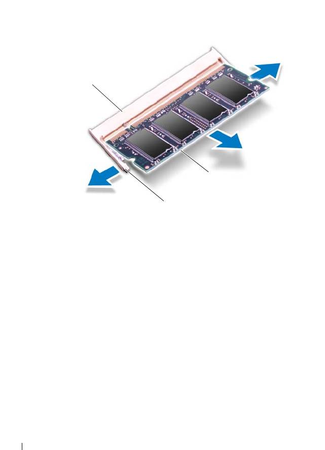
Use your fingertips to carefully spread apart the securing clips on each end
of the memory-module connector until the memory module pops up.
1 memory-module connector 2 securing clips (2)
3 memory module
5
Remove the memory module from the memory-module connector.
Replacing the Memory Module(s)
1
Follow the instructions in "Before You Begin" on page 7.
2
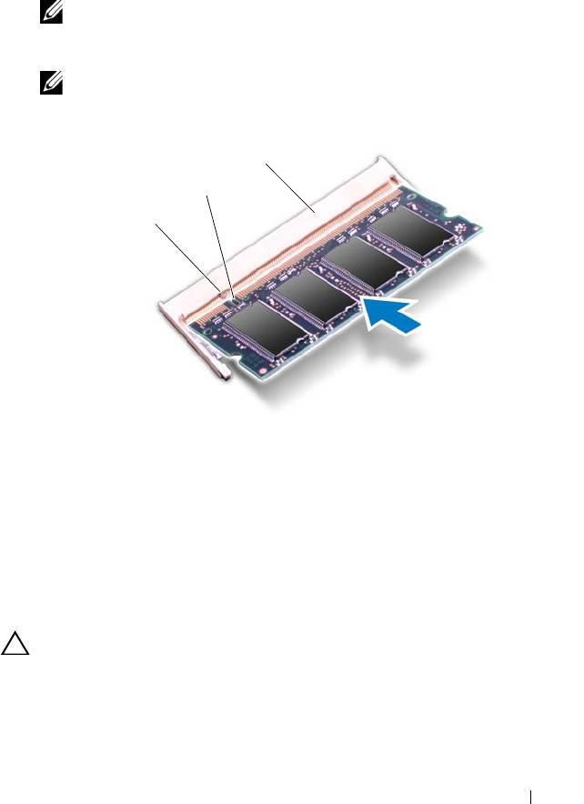
Align the notch in the memory module with the tab in the
memory-module connector.
18 Memory Module(s)
1
3
2
book.book Page 18 Thursday, May 3, 2012 3:09 PM
3
Slide the memory module firmly into the memory-module connector at a
45-degree angle, and press the memory module down until it clicks into
place. If you do not hear the click, remove the memory module and
reinstall it.
NOTE: Replace the system board after replacing the secondary memory
module. To replace the system board, see "Replacing the System Board" on
page 48.
NOTE: If the memory module is not installed properly, the computer may
not boot.
1 tab 2 notch
3 memory-module connector
4
Replace the battery (see "Replacing the Battery" on page 16).
5
Replace the base cover (see "Replacing the Base Cover" on page 12).
6
Connect the AC adapter to your computer and an electrical outlet.
CAUTION: Before turning on the computer, replace all screws and ensure that no
stray screws remain inside the computer. Failure to do so may result in damage to
the computer.
7
Turn on the computer.
Memory Module(s) 19
3
2
1
book.book Page 19 Thursday, May 3, 2012 3:09 PM

book.book Page 20 Thursday, May 3, 2012 3:09 PM
As the computer boots, it detects the additional memory and automatically
updates the system configuration information.
To confirm the amount of memory installed in the computer:
Click Start Control PanelSystem.
20 Memory Module(s)
