Dell XPS 14Z (L412z) – страница 2
Инструкция к Ноутбуку Dell XPS 14Z (L412z)
Оглавление

book.book Page 21 Thursday, May 3, 2012 3:09 PM
5
Wireless Mini-Card
WARNING: Before working inside your computer, read the safety information
that shipped with your computer. For additional safety best practices
information, see the Regulatory Compliance Homepage at
www.dell.com/regulatory_compliance.
CAUTION: Only a certified service technician should perform repairs on your
computer. Damage due to servicing that is not authorized by Dell is not covered
by your warranty.
CAUTION: To avoid electrostatic discharge, ground yourself by using a wrist
grounding strap or by periodically touching an unpainted metal surface (such as
a connector on your computer).
CAUTION: To help prevent damage to the system board, remove the main battery
(see "Removing the Battery" on page 15) before working inside the computer.
NOTE: Dell does not guarantee compatibility or provide support for Mini-Cards
from sources other than Dell.
If you ordered a wireless Mini-Card with your computer, the card is already
installed.
Your computer has one half Mini-Card slot which supports a Wireless Local
Area Network (WLAN) + Bluetooth combo card.
NOTE: Depending on the configuration of the computer when it was sold, the
Mini-Card slot may or may not have a Mini-Card installed.
Removing the Mini-Card
1
Follow the instructions in "Before You Begin" on page 7.
2
Remove the base cover (see "Removing the Base Cover" on page 11).
3
Remove the battery (see "Removing the Battery" on page 15).
4
Disconnect the antenna cables from the Mini-Card.
5
Remove the screw that secures the Mini-Card to the system board.
Wireless Mini-Card 21
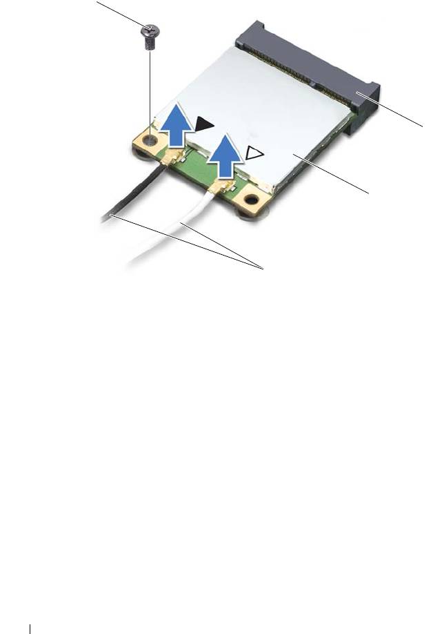
1 antenna cables (2) 2 Mini-Card
3 system-board connector 4 screw
6
Lift the Mini-Card out of the system-board connector.
22 Wireless Mini-Card
4
3
2
1
book.book Page 22 Thursday, May 3, 2012 3:09 PM
book.book Page 23 Thursday, May 3, 2012 3:09 PM
CAUTION: When the Mini-Card is not in the computer, store it in protective
antistatic packaging. For more information, see "Protecting Against Electrostatic
Discharge" in the safety information that shipped with your computer.
Replacing the Mini-Card
1
Follow the instructions in "Before You Begin" on page 7.
2
Remove the new Mini-Card from its packaging.
CAUTION: Use firm and even pressure to slide the Mini-Card into place. If you
use excessive force, you may damage the connector.
CAUTION: The connectors are keyed to ensure correct insertion. If you feel
resistance, check the connectors on the Mini-Card and on the system board, and
realign the Mini-Card.
CAUTION: To avoid damage to the Mini-Card, never place cables under the
Mini-Card.
Wireless Mini-Card 23

book.book Page 24 Thursday, May 3, 2012 3:09 PM
3
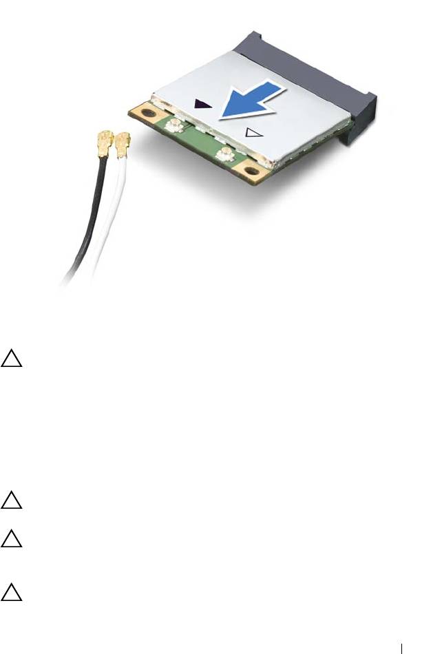
Insert the Mini-Card connector at a 45-degree angle into the system-board
connector.
4
Press the other end of the Mini-Card down into the slot on the system
board and replace the screw that secures the Mini-Card to the system
board.
5
Connect the appropriate antenna cables to the Mini-Card you are
installing.
Connectors on the Mini-Card Antenna Cable Color Scheme
WLAN + Bluetooth (2 antenna cables)
Main WLAN + Bluetooth (white triangle)
white
Auxiliary WLAN + Bluetooth (black triangle)
black
6
Replace the battery (see "Replacing the Battery" on page 16).
7
Replace the base cover (see "Replacing the Base Cover" on page 12).
CAUTION: Before turning on the computer, replace all screws and ensure that
no stray screws remain inside the computer. Failure to do so may result in damage
to the computer.
8
Install the drivers and utilities for your Mini-Card, as required.
NOTE: If you are installing a Mini-Card from a source other than Dell, you must
install the appropriate drivers and utilities.
24 Wireless Mini-Card

book.book Page 25 Thursday, May 3, 2012 3:09 PM
6
Hard Drive
WARNING: Before working inside your computer, read the safety information
that shipped with your computer. For additional safety best practices information,
see the Regulatory Compliance Homepage at
www.dell.com/regulatory_compliance.
WARNING: If you remove the hard drive from the computer when the drive is hot,
do not touch
the metal housing of the hard drive.
CAUTION: Only a certified service technician should perform repairs on your
computer. Damage due to servicing that is not authorized by Dell is not covered by
your warranty.
CAUTION: To avoid electrostatic discharge, ground yourself by using a wrist
grounding strap or by periodically touching an unpainted metal surface (such as a
connector on your computer).
CAUTION: To help prevent damage to the system board, remove the main battery
(see "Removing the Battery" on page 15) before working inside the computer.
CAUTION: To prevent data loss, turn off your computer (see "Turning Off Your
Computer" on page 7) before removing the hard drive. Do not remove the hard drive
while the computer is On or in Sleep state.
CAUTION: Hard drives are extremely fragile. Exercise care when handling the
hard drive.
NOTE: Dell does not guarantee compatibility or provide support for hard drives
from sources other than Dell.
NOTE: If you are installing a hard drive from a source other than Dell, you need to
install an operating system, drivers, and utilities on the new hard drive.
Removing the Hard Drive
1
Follow the instructions in "Before You Begin" on page 7.
2
Remove the base cover (see "Removing the Base Cover" on page 11).
3
Remove the battery (see "Removing the Battery" on page 15).
4
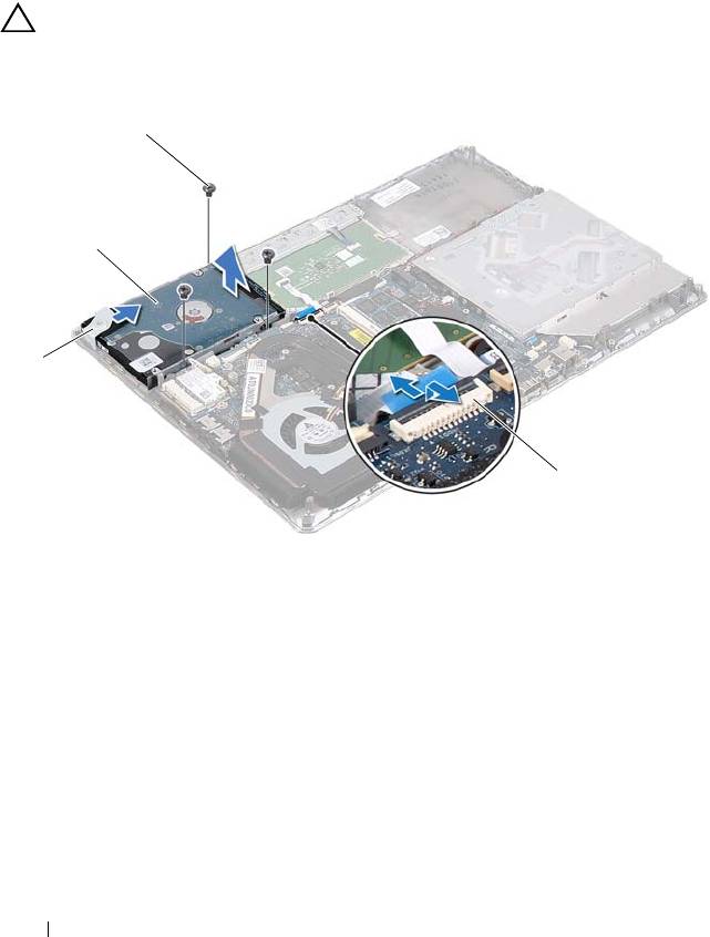
Remove the three screws that secure the hard-drive assembly to the
palm-rest assembly.
Hard Drive 25
5
Lift the connector latch and pull the pull-tab to disconnect the hard-drive
cable from the system-board connector.
6
Slide the hard-drive assembly away from the bracket on the palm-rest
assembly.
7
Lift the hard-drive assembly out of the palm-rest assembly.
CAUTION: When the hard drive is not in the computer, store it in protective
antistatic packaging (see "Protecting Against Electrostatic Discharge" in the
safety instructions that shipped with your computer).
1 bracket 2 hard-drive assembly
3 screws (3) 4 hard-drive cable connector
8
Remove the four screws that secure the hard-drive bracket to the hard
drive.
9
Lift the hard-drive bracket off the hard drive.
26 Hard Drive
3
2
1
4
book.book Page 26 Thursday, May 3, 2012 3:09 PM
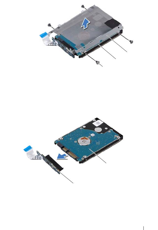
1 screws (4) 2 hard drive
3 hard-drive bracket
10
Disconnect the interposer from the hard drive.
1 interposer 2 hard drive
Hard Drive 27
3
2
1
2
1
book.book Page 27 Thursday, May 3, 2012 3:09 PM

book.book Page 28 Thursday, May 3, 2012 3:09 PM
Replacing the Hard Drive
1
Follow the instructions in "Before You Begin" on page 7.
2
Remove the new hard drive from its packaging.
Save the original packaging for storing or shipping the hard drive.
3
Connect the interposer to the hard drive.
4
Place the hard-drive bracket on the hard drive.
5
Replace the four screws that secure the hard-drive bracket to the hard
drive.
6
Slide the hard-drive assembly into the bracket on the palm-rest assembly.
7
Replace the three screws that secure the hard-drive assembly to the
palm-rest assembly.
8
Slide the hard-drive cable into the system-board connector and press down
on the connector latch to secure the cable.
9
Replace the battery (see "Replacing the Battery" on page 16).
10
Replace the base cover (see "Replacing the Base Cover" on page 12).
CAUTION: Before turning on the computer, replace all screws and ensure that no
stray screws remain inside the computer. Failure to do so may result in damage to
the computer.
28 Hard Drive

book.book Page 29 Thursday, May 3, 2012 3:09 PM
7
Coin-Cell Battery
WARNING: Before working inside your computer, read the safety information
that shipped with your computer. For additional safety best practices information,
see the Regulatory Compliance Homepage at
www.dell.com/regulatory_compliance.
CAUTION: Only a certified service technician should perform repairs on your
computer. Damage due to servicing that is not authorized by Dell is not covered by
your warranty.
CAUTION: To avoid electrostatic discharge, ground yourself by using a wrist
grounding strap or by periodically touching an unpainted metal surface (such as a
connector on your computer).
CAUTION: To help prevent damage to the system board, remove the main battery
(see "Removing the Battery" on page 15) before working inside the computer.
Removing the Coin-Cell Battery
1
Follow the instructions in "Before You Begin" on page 7.
2
Remove the base cover (see "Removing the Base Cover" on page 11).
3
Remove the battery (see "Removing the Battery" on page 15).
4
Disconnect the coin-cell battery cable from the system-board connector.
5
Peel the coin-cell battery off the system board.
Coin-Cell Battery 29
1 coin-cell-battery 2 coin-cell battery cable
Replacing the Coin-Cell Battery
1
Follow the instructions in "Before You Begin" on page 7.
2
Adhere the coin-cell battery to the system board.
3
Connect the coin-cell battery cable to the system-board connector.
4
Replace the battery (see "Replacing the Battery" on page 16).
5
Replace the base cover (see "Replacing the Base Cover" on page 12).
CAUTION: Before turning on the computer, replace all screws and ensure that no
stray screws remain inside the computer. Failure to do so may result in damage to
the computer.
30 Coin-Cell Battery
2
1
book.book Page 30 Thursday, May 3, 2012 3:09 PM

book.book Page 31 Thursday, May 3, 2012 3:09 PM
8
Optical Drive
WARNING: Before working inside your computer, read the safety information
that shipped with your computer. For additional safety best practices information,
see the Regulatory Compliance Homepage at
www.dell.com/regulatory_compliance.
CAUTION: Only a certified service technician should perform repairs on your
computer. Damage due to servicing that is not authorized by Dell is not covered by
your warranty.
CAUTION: To avoid electrostatic discharge, ground yourself by using a wrist
grounding strap or by periodically touching an unpainted metal surface (such as a
connector on your computer).
CAUTION: To help prevent damage to the system board, remove the main battery
(see "Removing the Battery" on page 15) before working inside the computer.
Removing the Optical Drive
1
Follow the instructions in "Before You Begin" on page 7.
2
Remove the base cover (see "Removing the Base Cover" on page 11).
3
Remove the battery (see "Removing the Battery" on page 15).
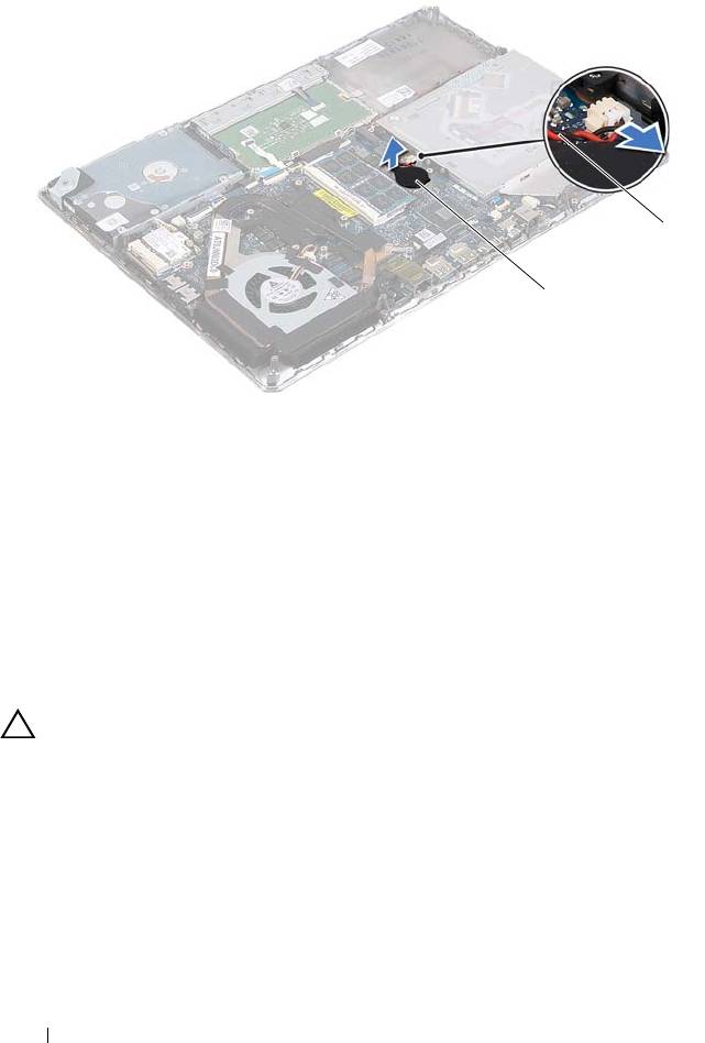
4
Remove the screw that secures the optical-drive assembly to the palm-rest
assembly.
5
Slide the optical-drive assembly to the side to release it from the bracket
and tabs on the palm-rest assembly.
Optical Drive 31
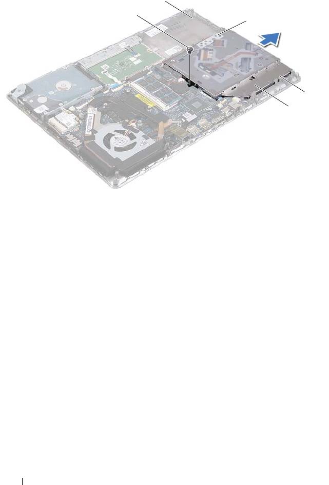
1 screw 2 palm-rest assembly
3 bracket 4 tabs (3)
5 optical-drive assembly
6
Remove the two screws that secure the optical-drive bracket to the optical
drive.
7
Remove the optical-drive bracket from the optical drive.
32 Optical Drive
2
1
3
4
5
book.book Page 32 Thursday, May 3, 2012 3:09 PM
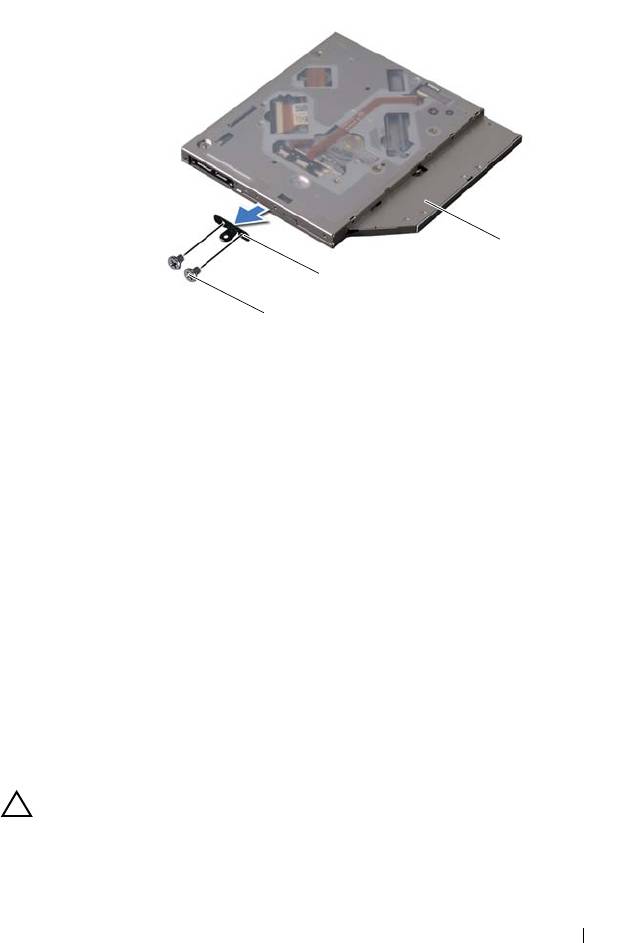
1 screws
(
2
)
2 optical-drive bracket
3 optical drive
Replacing the Optical Drive
1
Follow the instructions in "Before You Begin" on page 7.
2
Place the optical-drive bracket in position.
3
Replace the two screws that secure the optical-drive bracket to the optical
drive.
4
Slide the optical-drive assembly into the bracket and tabs on the palm-rest
assembly.
5
Replace the screw that secures the optical-drive assembly to the palm-rest
assembly.
6
Replace the battery (see "Replacing the Battery" on page 16).
7
Replace the base cover (see "Replacing the Base Cover" on page 12).
CAUTION: Before turning on the computer, replace all screws and ensure that no
stray screws remain inside the computer. Failure to do so may result in damage to
the computer.
Optical Drive 33
3
2
1
book.book Page 33 Thursday, May 3, 2012 3:09 PM

book.book Page 34 Thursday, May 3, 2012 3:09 PM
34 Optical Drive

book.book Page 35 Thursday, May 3, 2012 3:09 PM
9
Hall-Sensor Board
WARNING: Before working inside your computer, read the safety information
that shipped with your computer. For additional safety best practices
information, see the Regulatory Compliance Homepage at
www.dell.com/regulatory_compliance.
CAUTION: Only a certified service technician should perform repairs on your
computer. Damage due to servicing that is not authorized by Dell is not covered by
your warranty.
CAUTION: To avoid electrostatic discharge, ground yourself by using a wrist
grounding strap or by periodically touching an unpainted metal surface (such as
a connector on your computer).
CAUTION: To help prevent damage to the system board, remove the main battery
(see "Removing the Battery" on page 15) before working inside the computer.
Removing the Hall-Sensor Board
1
Follow the instructions in "Before You Begin" on page 7.
2
Remove the base cover (see "Removing the Base Cover" on page 11).
3
Remove the battery (see "Removing the Battery" on page 15).
4
Remove the hard drive (see "Removing the Hard Drive" on page 25).
5
Without pulling hard on the sponge pad, carefully lift the sponge pad from
the inside edge of the computer.
Hall-Sensor Board 35
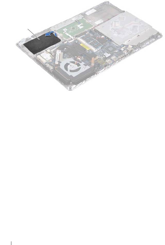
1 sponge pad
6
Lift the connector latch and pull the pull-tab to disconnect the
hall-sensor-board cable from the system-board connector.
7
Remove the screw that secures the hall-sensor board to the palm-rest
assembly.
8
Lift the hall-sensor board away from the palm-rest assembly.
36 Hall-Sensor Board
1
book.book Page 36 Thursday, May 3, 2012 3:09 PM
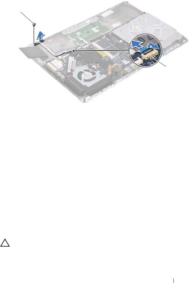
1 screw 2 system-board connector
Replacing the Hall-Sensor Board
1
Follow the instructions in "Before You Begin" on page 7.
2
Align the screw hole on the hall-sensor board with the screw hole on the
palm-rest assembly.
3
Replace the screw that secures the hall-sensor board to the palm-rest
assembly.
4
Slide the hall-sensor-board cable into the system-board connector and
press down on the connector latch to secure the cable.
5
Adhere the sponge pad to the palm-rest assembly.
6
Replace the hard drive (see "Replacing the Hard Drive" on page 28).
7
Replace the battery (see "Replacing the Battery" on page 16).
8
Replace the base cover (see "Replacing the Base Cover" on page 12).
CAUTION: Before turning on the computer, replace all screws and ensure that no
stray screws remain inside the computer. Failure to do so may result in damage to
the computer.
Hall-Sensor Board 37
1
2
book.book Page 37 Thursday, May 3, 2012 3:09 PM

book.book Page 38 Thursday, May 3, 2012 3:09 PM
38 Hall-Sensor Board

book.book Page 39 Thursday, May 3, 2012 3:09 PM
10
Display-Converter Board
WARNING: Before working inside your computer, read the safety information
that shipped with your computer. For additional safety best practices information,
see the Regulatory Compliance Homepage at
www.dell.com/regulatory_compliance.
CAUTION: Only a certified service technician should perform repairs on your
computer. Damage due to servicing that is not authorized by Dell is not covered by
your warranty.
CAUTION: To avoid electrostatic discharge, ground yourself by using a wrist
grounding strap or by periodically touching an unpainted metal surface (such as a
connector on your computer).
CAUTION: To help prevent damage to the system board, remove the main battery
(see "Removing the Battery" on page 15) before working inside the computer.
Removing the Display-Converter Board
1
Follow the instructions in "Before You Begin" on page 7.
2
Remove the base cover (see "Removing the Base Cover" on page 11).
3
Remove the battery (see "Removing the Battery" on page 15).
4
Disconnect the display-converter-board cable from the system-board
connector.
5
Remove the two screws that secure the display-converter board to the
palm-rest assembly.
6
Without pulling hard on the display-converter board, carefully lift the
display-converter board and turn it over.
7
Disconnect the display-converter-board cable and the display cable from
the connectors on the display-converter board.
8
Lift the display-converter board out of the computer.
Display-Converter Board 39
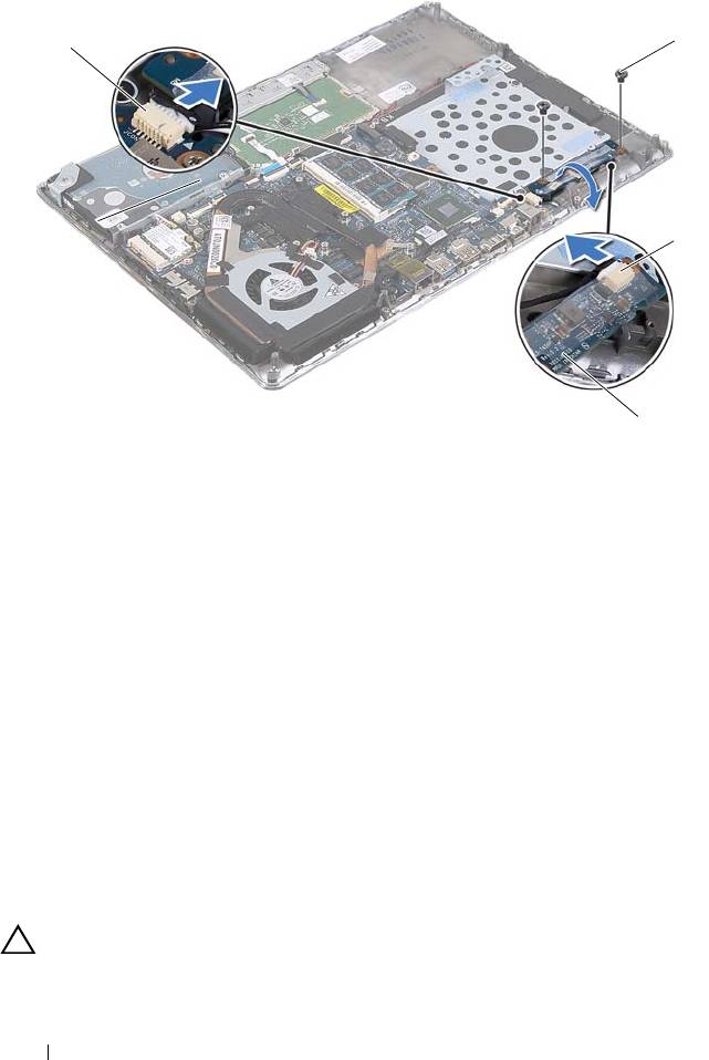
1 system-board connector 2 screws (2)
3 display cable connector 4 display-converter board
Replacing the Display-Converter Board
1
Follow the instructions in "Before You Begin" on page 7.
2
Connect the display-converter-board cable, and the display cable to the
connectors on the display-converter board.
3
Align the screw holes on the display-converter board with the screw holes
on the palm-rest assembly.
4
Replace the two screws that secure the display-converter board to the
palm-rest assembly.
5
Connect the display-converter-board cable to the system-board connector.
6
Replace the battery (see "Replacing the Battery" on page 16).
7
Replace the base cover (see "Replacing the Base Cover" on page 12).
CAUTION: Before turning on the computer, replace all screws and ensure that no
stray screws remain inside the computer. Failure to do so may result in damage to
the computer.
40 Display-Converter Board
2
1
2
3
4
book.book Page 40 Thursday, May 3, 2012 3:09 PM
