Dell XPS 14Z (L412z) – страница 3
Инструкция к Ноутбуку Dell XPS 14Z (L412z)
Оглавление

book.book Page 41 Thursday, May 3, 2012 3:09 PM
11
Heat Sink and Fan
WARNING: Before working inside your computer, read the safety information
that shipped with your computer. For additional safety best practices information,
see the Regulatory Compliance Homepage at
www.dell.com/regulatory_compliance.
WARNING: If you remove the heat sink from the computer when the heat sink is
hot,
do not touch
the metal housing of the heat sink.
CAUTION: Only a certified service technician should perform repairs on your
computer. Damage due to servicing that is not authorized by Dell is not covered by
your warranty.
CAUTION: To avoid electrostatic discharge, ground yourself by using a wrist
grounding strap or by periodically touching an unpainted metal surface (such as a
connector on your computer).
CAUTION: To help prevent damage to the system board, remove the main battery
(see "Removing the Battery" on page 15) before working inside the computer.
Removing the Heat Sink and Fan
1
Follow the instructions in "Before You Begin" on page 7.
2
Remove the base cover (see "Removing the Base Cover" on page 11).
3
Remove the battery (see "Removing the Battery" on page 15).
4
Using your fingertips gently peel off the display cable tape from the
heat sink.
5
Disconnect the fan cable from the system-board connector.
6
In sequential order (indicated on the heat sink), remove the six screws that
secure the heat sink to the system board.
7
Lift the heat sink and fan away from the system board.
Heat Sink and Fan 41
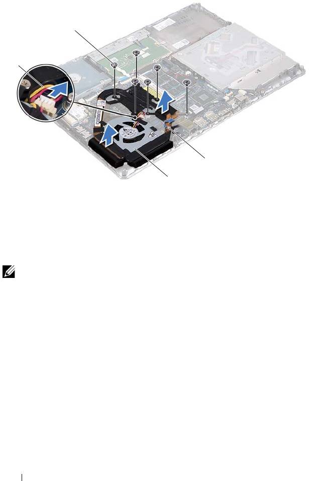
1 fan cable 2 screws (6)
3 display cable tape 4 heat sink and fan
Replacing the Heat Sink and Fan
NOTE: The original thermal grease can be reused if the original system board and
heat sink are reinstalled together. If either the system board or the heat sink is
replaced, use the thermal pad provided in the kit to ensure that thermal conductivity
is achieved.
1
Follow the instructions in "Before You Begin" on page 7.
2
Clean the thermal grease from the bottom of the heat sink and reapply it.
3
Align the screw holes on the heat sink with the screw holes on the system
board.
4
In sequential order (indicated on the heat sink), replace the six screws that
secure the heat sink to the system board.
5
Connect the fan cable to the system-board connector.
6
Adhere the display cable tape to the heat sink.
42 Heat Sink and Fan
2
1
3
4
book.book Page 42 Thursday, May 3, 2012 3:09 PM

book.book Page 43 Thursday, May 3, 2012 3:09 PM
7
Replace the battery (see "Replacing the Battery" on page 16).
8
Replace the base cover (see "Replacing the Base Cover" on page 12).
CAUTION: Before turning on the computer, replace all screws and ensure that no
stray screws remain inside the computer. Failure to do so may result in damage to
the computer.
Heat Sink and Fan 43

book.book Page 44 Thursday, May 3, 2012 3:09 PM
44 Heat Sink and Fan

book.book Page 45 Thursday, May 3, 2012 3:09 PM
12
System Board
WARNING: Before working inside your computer, read the safety information
that shipped with your computer. For additional safety best practices
information, see the Regulatory Compliance Homepage at
www.dell.com/regulatory_compliance.
CAUTION: Only a certified service technician should perform repairs on your
computer. Damage due to servicing that is not authorized by Dell is not covered by
your warranty.
CAUTION: To avoid electrostatic discharge, ground yourself by using a wrist
grounding strap or by periodically touching an unpainted metal surface (such as a
connector on your computer).
CAUTION: To help prevent damage to the system board, remove the main battery
(see "Removing the Battery" on page 15) before working inside the computer.
CAUTION: Handle components and cards by their edges, and avoid touching pins
and contacts.
Removing the System Board
1
Follow the instructions in "Before You Begin" on page 7.
2
Remove any installed card or blank from the Media Card Reader.
3
Remove the base cover (see "Removing the Base Cover" on page 11).
4
Remove the battery (see "Removing the Battery" on page 15).
5
Remove the Mini-Card (see "Removing the Mini-Card" on page 21).
6
Remove the hard drive (see "Removing the Hard Drive" on page 25).
7
Remove the coin-cell battery (see "Removing the Coin-Cell Battery" on
page 29).
8
Remove the optical drive (see "Removing the Optical Drive" on page 31).
9
Remove the heat sink and fan (see "Removing the Heat Sink and Fan" on
page 41).
10
Gently peel off the keyboard-cable pull tab from the keyboard cable
connector on the system board.
System Board 45
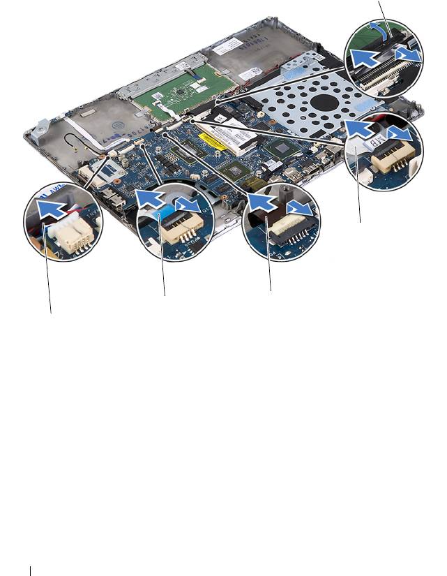
11
Disconnect the speaker cable from the system-board connector.
12
Lift the connector latch and pull the pull-tab to disconnect the keyboard
cable, touch-pad cable, keyboard-backlight cable, and hall-sensor cable
from the system-board connectors.
1 speaker cable 2 hall-sensor cable
3 keyboard backlight cable 4 touch-pad cable
5 keyboard cable pull-tab
13
Gently peel off the tape from the network connector on the system board.
14
Lift the connector latch and pull the pull-tab to disconnect the power-
button board cable from the system-board connector.
15
Disconnect the display cable, ambient-light-sensor cable, and display-
converter board cable from the system-board connectors.
46 System Board
5
4
3
2
1
book.book Page 46 Thursday, May 3, 2012 3:09 PM
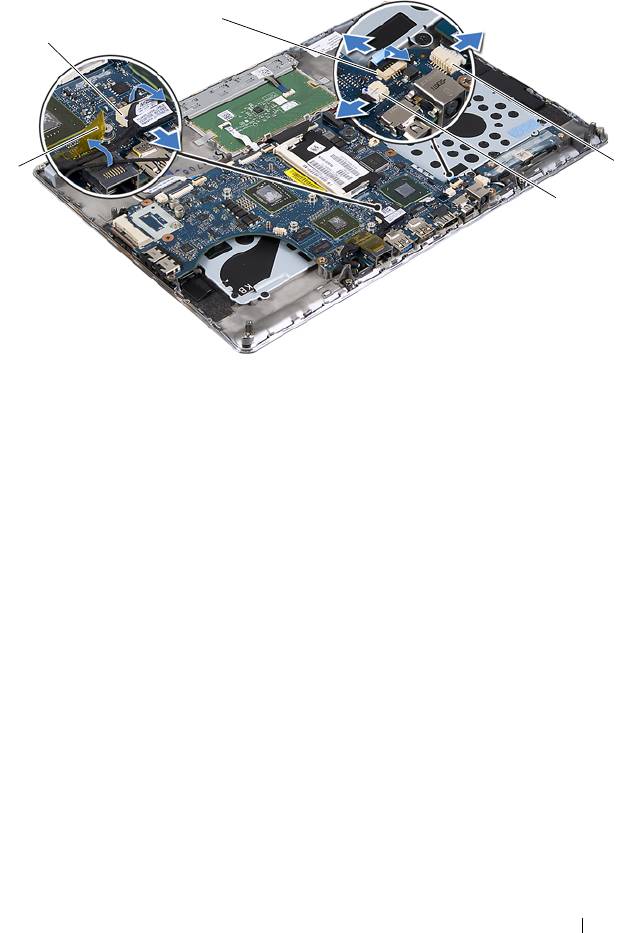
1 tape 2 display cable connector
3 power-button board cable 4 display-converter board cable
connector
5 ambient-light-sensor cable
connector
16
Remove the five screws that secure the system board to the palm-rest
assembly.
17
Lift the system board off the palm-rest assembly.
18
Remove the memory module(s) (see "Removing the Memory Module(s)"
on page 17).
System Board 47
3
2
4
1
5
book.book Page 47 Thursday, May 3, 2012 3:09 PM
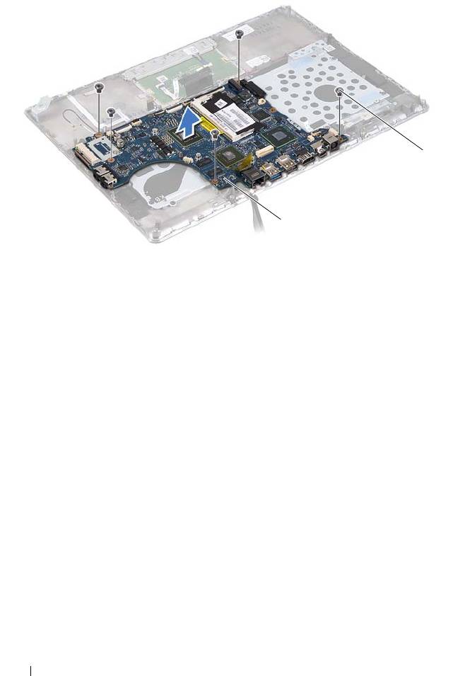
1 system board 2 screws (5)
Replacing the System Board
1
Follow the instructions in "Before You Begin" on page 7.
2
Replace the memory module(s) (see "Replacing the Memory Module(s)"
on page 18).
3
Place the system board on the palm-rest assembly.
4
Replace the five screws that secure the system board to the palm-rest
assembly.
5
Slide the power-button board cable into the system-board connector and
press down on the connector latch to secure the cable.
6
Connect the display cable, ambient-light-sensor cable, and display-
converter board cable to the system-board connectors.
7
Adhere the tape over the network connector on the system board.
8
Connect the speaker cable to the system-board connector.
9
Slide the keyboard cable, touch-pad cable, keyboard-backlight cable, and
hall-sensor cable into the system board connectors and press down on the
connector latch to secure the cable.
48 System Board
2
1
book.book Page 48 Thursday, May 3, 2012 3:09 PM

book.book Page 49 Thursday, May 3, 2012 3:09 PM
10
Adhere the pull-tab on the keyboard cable over the keyboard cable
connector on the system board.
11
Replace the heat sink and fan (see "Replacing the Heat Sink and Fan" on
page 42).
12
Replace the optical drive (see "Replacing the Optical Drive" on page 33).
13
Replace the coin-cell battery (see "Replacing the Coin-Cell Battery" on
page 30).
14
Replace the hard drive (see "Replacing the Hard Drive" on page 28).
15
Replace the Mini-Card (see "Replacing the Mini-Card" on page 23).
16
Replace the battery (see "Replacing the Battery" on page 16).
17
Replace the base cover (see "Replacing the Base Cover" on page 12).
18
Replace any blank or card you removed from the Media Card Reader.
CAUTION: Before turning on the computer, replace all screws and ensure that no
stray screws remain inside the computer. Failure to do so may result in damage to
the computer.
19
Turn on the computer.
NOTE: After you have replaced the system board, enter the computer Service Tag
in the BIOS of the replacement system board.
20
Enter the Service Tag (see "Entering the Service Tag in the BIOS" on
page 49).
Entering the Service Tag in the BIOS
1
Ensure that the AC adapter is plugged in and that the main battery is
installed properly.
2
Turn on the computer.
3
Press <F2> during POST to enter the System Setup program.
4
Navigate to the Security tab and enter the Service Tag in the
Set Service
Ta g
field.
System Board 49

book.book Page 50 Thursday, May 3, 2012 3:09 PM
50 System Board

book.book Page 51 Thursday, May 3, 2012 3:09 PM
13
Power-Button Board
WARNING: Before working inside your computer, read the safety information
that shipped with your computer. For additional safety best practices information,
see the Regulatory Compliance Homepage at
www.dell.com/regulatory_compliance.
CAUTION: Only a certified service technician should perform repairs on your
computer. Damage due to servicing that is not authorized by Dell is not covered by
your warranty.
CAUTION: To avoid electrostatic discharge, ground yourself by using a wrist
grounding strap or by periodically touching an unpainted metal surface (such as a
connector on your computer).
CAUTION: To help prevent damage to the system board, remove the main battery
(see "Removing the Battery" on page 15) before working inside the computer.
Removing the Power-Button Board
1
Follow the instructions in "Before You Begin" on page 7.
2
Remove the system board (see "Removing the System Board" on page 45).
3
Remove the two screws that secure the power-button board to the
palm-rest assembly.
4
Lift the power-button board along with the cable away from the palm-rest
assembly.
Power-Button Board 51
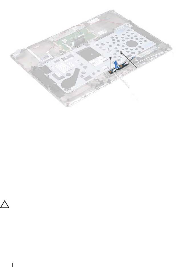
1 power-button board 2 screws (2)
Replacing the Power-Button Board
1
Follow the instructions in "Before You Begin" on page 7.
2
Use the alignment posts to place the power-button board on the palm-rest
assembly.
3
Replace the two screws that secure the power-button board to the
palm-rest assembly.
4
Replace the system board (see "Replacing the System Board" on page 48).
CAUTION: Before turning on the computer, replace all screws and ensure that no
stray screws remain inside the computer. Failure to do so may result in damage to
the computer.
52 Power-Button Board
2
1
book.book Page 52 Thursday, May 3, 2012 3:09 PM

book.book Page 53 Thursday, May 3, 2012 3:09 PM
14
Keyboard
WARNING: Before working inside your computer, read the safety information
that shipped with your computer. For additional safety best practices information,
see the Regulatory Compliance Homepage at
www.dell.com/regulatory_compliance.
CAUTION: Only a certified service technician should perform repairs on your
computer. Damage due to servicing that is not authorized by Dell is not covered by
your warranty.
CAUTION: To avoid electrostatic discharge, ground yourself by using a wrist
grounding strap or by periodically touching an unpainted metal surface (such as a
connector on your computer).
CAUTION: To help prevent damage to the system board, remove the main battery
(see "Removing the Battery" on page 15) before working inside the computer.
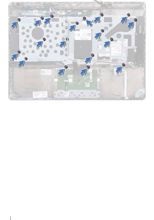
Removing the Keyboard Bracket
1
Follow the instructions in "Before You Begin" on page 7.
2
Remove the system board (see "Removing the System Board" on page 45).
3
Remove the 18 screws that secure the keyboard bracket to the palm-rest
assembly.
Keyboard 53
book.book Page 54 Thursday, May 3, 2012 3:09 PM
4
Make a note of the speakers cable routing and remove the speaker cables
from the routing guides.
54 Keyboard
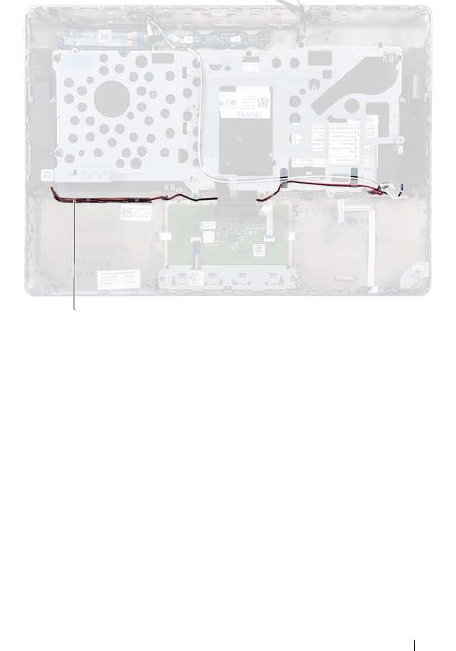
1 speakers cable
5
Make a note of the antenna cables routing and remove the antenna cables
from the routing guides.
Keyboard 55
1
book.book Page 55 Thursday, May 3, 2012 3:09 PM
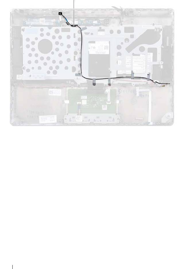
1 antenna cables (2)
6
Lift the keyboard bracket off the palm-rest assembly.
56 Keyboard
1
book.book Page 56 Thursday, May 3, 2012 3:09 PM
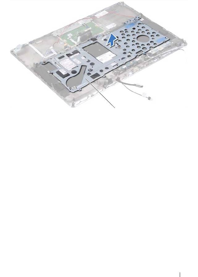
1 keyboard bracket
Replacing the Keyboard Bracket
1
Follow the instructions in "Before You Begin" on page 7.
2
Place the keyboard bracket on the palm-rest assembly.
3
Replace the 18 screws that secure the keyboard bracket to the palm-rest
assembly.
4
Route the speakers cable and antenna cables through the routing guides.
5
Replace the system board (see "Replacing the System Board" on page 48).
Keyboard 57
1
book.book Page 57 Thursday, May 3, 2012 3:09 PM
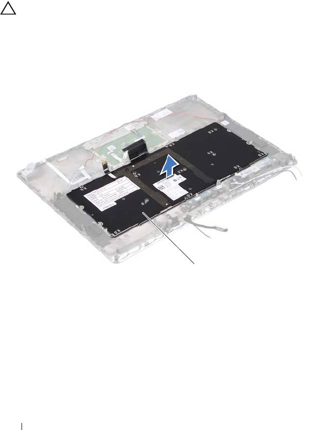
Removing the Keyboard
1
Follow the instructions in "Before You Begin" on page 7.
2
Remove the keyboard bracket (see "Removing the Keyboard Bracket" on
page 53).
CAUTION: The keycaps on the keyboard are fragile, easily dislodged, and time-
consuming to replace. Be careful when removing and handling the keyboard.
3
Lift the keyboard off the palm-rest assembly.
1 keyboard
58 Keyboard
1
book.book Page 58 Thursday, May 3, 2012 3:09 PM

book.book Page 59 Thursday, May 3, 2012 3:09 PM
Replacing the Keyboard
1
Follow the instructions in "Before You Begin" on page 7.
2
Place the keyboard on the palm-rest assembly.
3
Replace the keyboard bracket (see "Replacing the Keyboard Bracket" on
page 57).
CAUTION: Before turning on the computer, replace all screws and ensure that no
stray screws remain inside the computer. Failure to do so may result in damage to
the computer.
Keyboard 59

book.book Page 60 Thursday, May 3, 2012 3:09 PM
60 Keyboard
