Dell Precision M20 – страница 4
Инструкция к Ноутбуку Dell Precision M20
Оглавление
Back to Contents Page
Passwords
DellPrecision™MobileWorkstationM20User'sGuide
About Passwords
Using a Primary Password
Using an Administrator Password
Using a Hard Drive Password
Assigning an Asset Tag
Enabling Trusted Platform Module (TPM)
About Passwords
A primary password, an administrator password, and a hard drive password all prevent unauthorized access to your computer in different ways. The following
table identifies types and features of passwords available on your computer.
If you forget any of your passwords, contact your system administrator or contact Dell. For your protection, Dell technical support staff will ask you for proof of
your identity to ensure that only an authorized person can use the computer.
Using a Primary Password
The primary password allows you to protect the computer from unauthorized access.
After assigning a primary password, you must enter it each time you turn on your computer. The following message appears each time you turn on the
computer:
Please type in the primary or administrator password and press <Enter>.
To continue, enter your password (with no more than eight characters).
If you do not enter a password within 2 minutes, the computer returns to its previous operating state.
If you have assigned an administrator password, you can use it instead of the primary password. The computer does not specifically prompt you for the
administrator password.
Using an Administrator Password
The administrator password is designed to give system administrators or service technicians access to computers for repair or reconfiguration. The
administrators or technicians can assign identical administrator passwords to groups of computers, allowing you to assign the primary password.
When you set an administrator password, the Configure Setup option becomes available in system setup. The Configure Setup option allows you to restrict
NOTE: Passwords are disabled when you receive your computer.
Type of Password
Features
Primary
l Protects the computer from unauthorized
access
Administrator
l Gives system administrators or service
technicians access to computers for repair or
reconfiguration
l Allows you to restrict access to system setup
in the same way a primary password restricts
access to the computer
l Can be used instead of the primary password
Hard drive
l Helps protect the data on your hard drive or
external hard drive (if one is being used) from
unauthorized access
NOTE: OnlyharddrivespurchasedfromDellforusewiththeDellPrecision™D-Family computers support hard drive passwords.
NOTICE: Passwords provide a high level of security for data in your computer or hard drive. However, they are not foolproof. If you require more
security, obtain and use additional forms of protection, such as smart cards, data encryption programs, or PC Cards with encryption features.
NOTICE: If you disable the administrator password, the primary password is also disabled.

access to system setup in the same way that a primary password restricts access to the computer.
The administrator password can be used instead of the primary password. Whenever you are prompted to enter the primary password, you can enter the
administrator password.
If you forget the primary password and do not have an administrator password assigned, or if you have both a primary and an administrator password
assigned but forget them both, contact your system administrator or contact Dell.
Using a Hard Drive Password
The hard drive password helps protect the data on your hard drive from unauthorized access. You can also assign a password for an external hard drive (if
one is being used) that can be the same as or different from the password for the primary hard drive.
After assigning a hard drive password, you must enter it each time you turn on the computer and each time you restore the computer to normal operation
from standby mode.
If the hard drive password is enabled, the following message appears each time you turn on the computer:
Please type in the hard-disk drive password and press <Enter>.
To continue, enter your password (with no more than eight characters). Press <Esc> to return the computer to its previous operating state.
If you do not enter a password within 2 minutes, the computer returns to its previous operating state.
If you enter the wrong password, the following message appears:
Invalid password
[Press Enter to retry]
If you do not enter the correct password in three attempts, the computer tries to start from another bootable device if the Boot First Device option in system
setup is set to allow start-up from another device. If the Boot First Device option is not set to allow the computer to start from another device, the computer
returns to the operating state it was in when you turned it on.
If the hard drive password, the external hard-drive password, and the primary password are the same, the computer prompts you only for the primary
password. If the hard drive password is different from the primary password, the computer prompts you for both. Two different passwords provide greater
security.
Assigning an Asset Tag
The Asset Tag utility allows you to enter an asset tag that you or your company assigns to the computer. After you enter an asset tag, the tag appears in the
system setup screens.
You can also use the Asset Tag utility to enter an owner tag that appears in the system log-on screen and with the primary password prompt.
Download the Dell Portables Asset Tag utility from the support.dell.com website to create bootable media (such as a bootable CD or floppy disk), and then
use the bootable media to assign an asset tag.
1. Save and close any open files and exit any open programs.
2. Ensure that you have a drive for the bootable media (such as a floppy drive or a CD drive).
3. Access the support.dell.com website. Download the Dell Portables Asset Tag utility for your system. Unzip the files and run the Asset Tag utility to
create the bootable media.
4. Boot the computer, using the bootable media:
a. Restart the computer.
b. Press<F12>immediatelyaftertheDELL™logoappears.
If the operating system logo appears, wait until you see the Microsoft®Windows®desktop, and then shut down the computer and try again.
c. Press the arrow keys to select the drive containing the bootable media and press <Enter>.
5. Type asset and a space followed by the new asset tag, and press <Enter>.
NOTICE: If you disable the administrator password, the primary password is also disabled.
NOTE: The administrator password provides access to the computer, but it does not provide access to the hard drive when a hard drive password is
assigned.
NOTE: The administrator password provides access to the computer, but it does not provide access to a hard drive that is protected by a hard drive
password.
NOTE: Some of these features may not be available for your computer or in certain countries.
NOTE: The Dell Portables Asset Tag utility may not be available as a download in certain countries.

For example, type the following command line and press <Enter>:
asset 1234$ABCD&
6. When the computer prompts you to verify the asset tag, type y.
The computer displays the new or modified asset tag and the Service Tag.
7. Restart your computer to exit the Asset Tag utility.
Viewing Existing Asset and Service Tags
1. Boot the computer using the bootable media you created in "Assigning an Asset Tag."
2. Type asset and press <Enter>.
Deleting an Asset Tag
1. Boot the computer using the bootable media you created in "Assigning an Asset Tag."
2. Type asset /d and press <Enter>.
3. When the computer prompts you to delete the asset tag, type y.
Assigning an Owner Tag
An owner tag can have up to 48 characters; any combination of letters, numbers, and spaces is valid.
1. Boot the computer using the bootable media you created in "Assigning an Asset Tag."
2. Type asset /o and a space followed by the new owner tag, and press <Enter>.
For example, type the following command line and press <Enter>:
asset /o ABC Company
3. When the computer prompts you to verify the owner tag, type y.
The computer displays the new owner tag.
NOTE: An asset tag can have up to 10 characters; any combination of characters excluding spaces is valid.
Deleting an Owner Tag
1. Boot the computer using the bootable media you created in "Assigning an Asset Tag."
2. Type asset /o /d and press <Enter>.
3. When the computer prompts you to delete the owner tag, type y.
Asset Tag Options
To use one of the asset tag options (see the following table):
1. Boot the computer using the bootable media you created in "Assigning an Asset Tag."
2. Type asset and a space followed by the option, and then press <Enter>.
Enabling Trusted Platform Module (TPM)
TPM is a hardware-based security feature that can be used to create and manage computer-generated encryption keys. When combined with security
software, TPM enhances existing network and computer security by enabling features such as file protection capabilities and protected e-mail. The TPM feature
isenabledthroughaTPMsystemsetupoption.
Enabling the TPM Feature
1. Turn on your computer.
2. Install the TPM Software.
The TPM software is factory-installed in the C:\Dell\TPM directory. It may also be downloaded from support.dell.com.
3. Run the setup.exe file. Follow the on-screen instructions to install the Broadcom Secure Foundation software.
If you are using TPM on your computer for the first time, proceed to step4, otherwise, continue with step5.
4. To enable the TPM software:
a. Restartthecomputerandpress<F2>duringthePowerOnSelfTesttoenterthesystemsetupprogram.
b. Open the Security menu in system setup.
c. Select the TPM Security menu option and press <Enter>.
d. Set the TPM security option to On.
e. Press <Esc> to exit the setup program.
f. If prompted, select Save/Exit.
5. Activate the TPM setup program:
a. Boot your computer to the Microsoft®Windows®operating system.
b. Click Start® Programs® Broadcom Security Platforms Tools. Then, click the icon for the Security Platform Initialization Wizard.
NOTE: For security, you cannot set, change, or delete the owner tag if the primary or administrator passwords are set.
Asset Tag Option
Description
/d
Deletes the asset tag
/o owner tag
Specifies a new owner tag
/o /d
Deletes the owner tag
/?
Displays the Asset Tag utility help screen
NOTE: The TPM feature supports encryption only if the operating system supports TPM. For more information, see the software documentation.
NOTICE: If you use TPM, you must follow the backup procedures in the documentation that came with the software to secure your TPM data and
encryption keys. In the event of these backups being incomplete, lost, or damaged, Dell will be unable to assist in the recovery of encrypted data.

c. Follow the on-screen instructions to activate the TPM setup program. You only need to activate the program once.
You will be prompted to reboot your computer once the process is complete.
6. Physically activate the TPM:
a. Restart the computer and press <F2> during the Power On Self Test to enter the system setup program.
b. Open the Security menu in system setup and select the TPM Activation menu option.
c. Set the TPM activation state to Activate.
d. Save the changes and restart your computer.
7. Initialize the TPM owner and user passwords:
a. Boot your computer to the Microsoft®Windows®operating system.
b. Click Start® Programs® Broadcom Security Platforms Tools. Then, click the icon for the Security Platform Initialization Wizard.
c. Follow the on-screen instructions for creating the TPM owner, user passwords, and credentials.
Back to Contents Page

Back to Contents Page
Using PC Cards
DellPrecision™MobileWorkstationM20User'sGuide
PC Card Types
PC Card Blanks
Extended PC Cards
Installing a PC Card
Removing a PC Card or Blank
PC Card Types
See "Specifications" for information on supported PC Cards.
The PC Card slot has one connector that supports a single Type I or Type II card. The PC Card slot supports CardBus technology and extended PC Cards.
"Type" of card refers to its thickness, not its functionality.
The PC Card slot supports CardBus technology and extended PC Cards. "Type" of card refers to its thickness, not its functionality.
PC Card Blanks
Your computer shipped with a plastic blank installed in the PC Card slot. Blanks protect unused slots from dust and other particles. Save the blank for use
when no PC Card is installed in the slot; blanks from other computers may not fit your computer.
To remove the blank, see "Removing a PC Card or Blank."
Extended PC Cards
An extended PC Card (for example, a wireless network adapter) is longer than a standard PC Card and extends outside the computer. Follow these
precautions when using extended PC Cards:
l Protect the exposed end of an installed card. Striking the end of the card can damage the system board.
l Always remove an extended PC Card before you pack the computer in its carrying case.
Installing a PC Card
You can install a PC Card in the computer while the computer is running. The computer automatically detects the card.
PC Cards are generally marked with a symbol (such as a triangle or an arrow) to indicate which end to insert into the slot. The cards are keyed to prevent
incorrect insertion. If card orientation is not clear, see the documentation that came with the card.
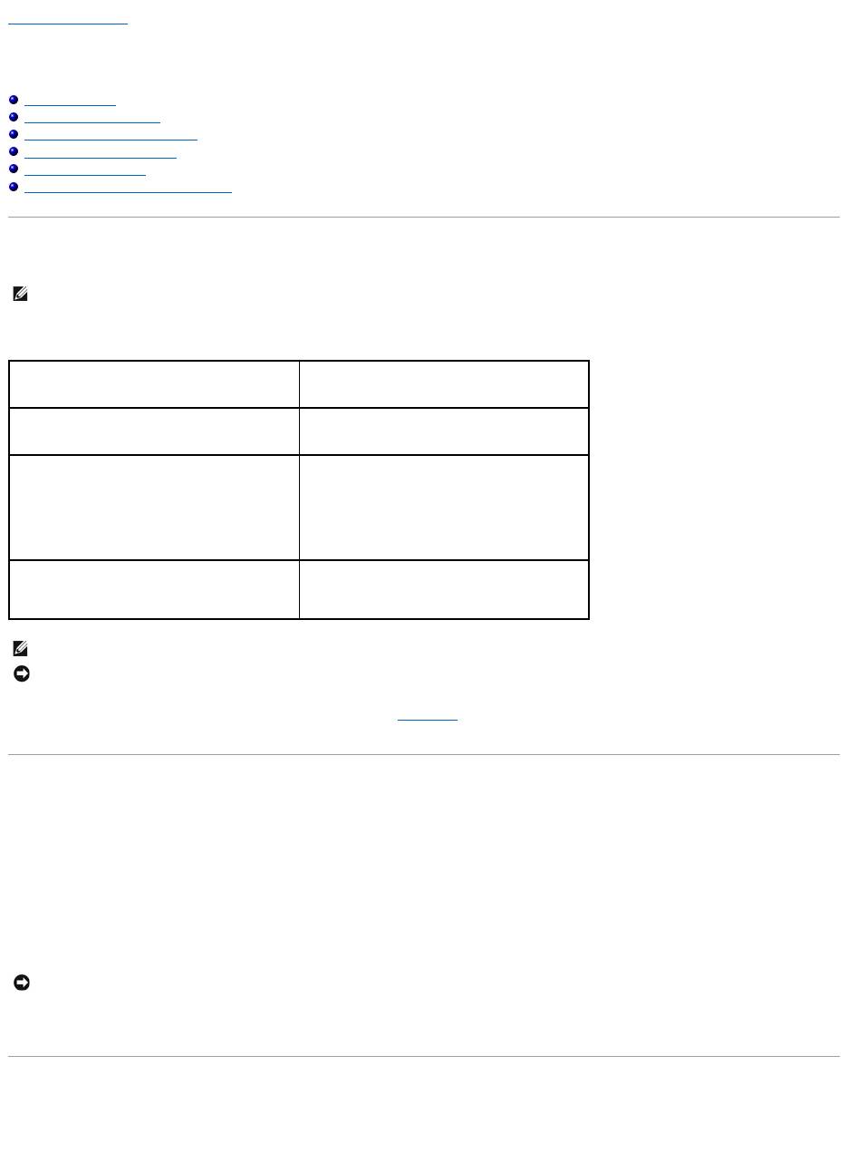
To install a PC Card:
1. Hold the card with its orientation symbol pointing into the slot and the top side of the card facing up. The latch may need to be in the "in" position
before you insert the card.
2. Slide the card into the slot until the card is completely seated in its connector.
If you encounter too much resistance, do not force the card. Check the card orientation and try again.
3. Rotate the latch closed after inserting the card.
NOTE: A PC Card is not a bootable device.
CAUTION: Before you begin any of the procedures in this section, follow the safety instructions in the Product Information Guide.
The computer recognizes most PC Cards and automatically loads the appropriate device driver. If the configuration program tells you to load the
manufacturer's drivers, use the floppy or CD that came with the PC Card.
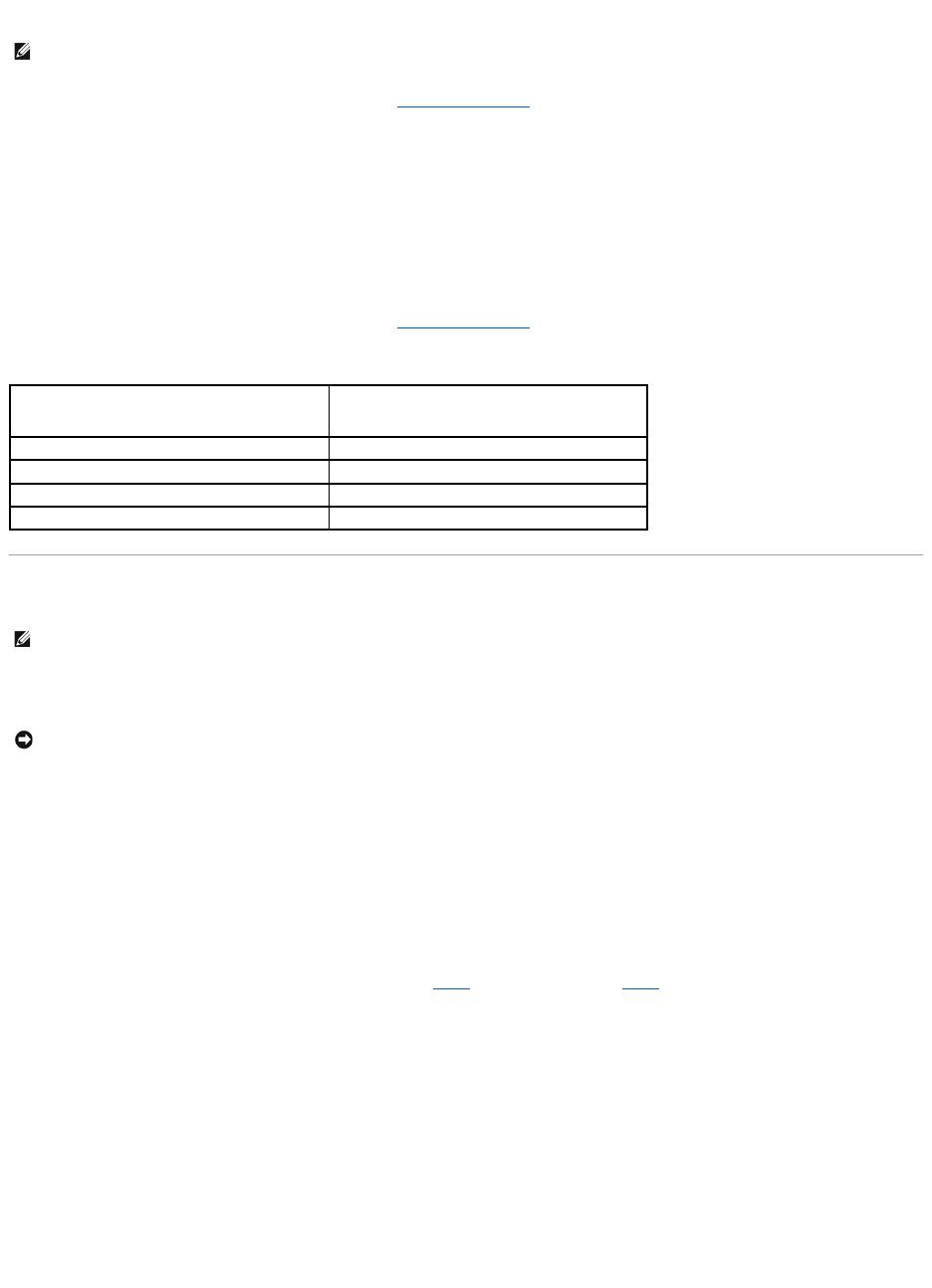
Removing a PC Card or Blank
Press the latch and remove the card or blank. For some latches, you must press the latch twice: once to pop the latch out, and then a second time to pop the
card out.
1. Rotate the latch outward.
2. Press in on the end of the latch.
3. Remove the card or blank.
Save a blank to use when no PC Card is installed in a slot. Blanks protect unused slots from dust and other particles.
Back to Contents Page
NOTICE: Use the PC Card configuration utility (click the icon in the taskbar) to select a card and stop it from functioning before you remove it from
the computer. If you do not stop the card in the configuration utility, you could lose data. Do not attempt to eject a card by pulling its cable, if one is
attached.
CAUTION: Before you begin any of the procedures in this section, follow the safety instructions in the Product Information Guide.
NOTE: This computer uses digital sound, and contains no analog audio lines. PCMCIA cards such as modems that use analog lines to produce sound will
not function.
1
eject button
2
PC card

Back to Contents Page
Power Management
DellPrecision™MobileWorkstationM20User'sGuide
Power Management Tips
Power Management Wizard
Power Management Modes
Power Options Properties
Power Management Tips
l Connect the computer to an electrical outlet when possible because battery life is largely determined by the number of times the battery is charged.
l Place the computer in standby mode or hibernate mode when you leave the computer unattended for long periods of time.
l You can use the Power Management Wizard to configure the computer to enter or exit power management modes by pressing the power button,
closing the display, or pressing <Fn><Esc>.
Power Management Wizard
Click or double-click the icon to open the Power Management Wizard.
The first two screens of the wizard—Welcome and What is Power Management?—describe and define various power management options.
Use the screens that follow Welcome and What is Power Management? to set various power management options, including sleep modes, power schemes,
and low battery-charge alarms.
Setting Sleep Modes
The screen defines standby and hibernate modes. From the screen you can:
l Set standby-mode password options.
l Enable or disable hibernate mode.
l Select how the computer will respond when you close the display:
¡ Choose no action.
¡ Enter standby mode.
¡ Enter hibernate mode.
l Select how the computer will respond when you press the power button:
¡ Choose no action.
¡ Enter standby mode.
¡ Enter hibernate mode.
¡ Shut down the operating system and turn off the computer.
¡ Prompt a user for an action (Ask me what to do).
l Select how the computer will respond when you press <Fn><Esc>:
¡ Choose no action.
¡ Enter standby mode.
¡ Enter hibernate mode.
¡ Shut down Microsoft Windows and turn off the computer.
¡ Prompt a user for an action (Ask me what to do).
NOTE: See "Using a Battery" for more information on conserving battery power.
NOTE: The Power Management Wizard is not available if you have restricted access rights.
NOTE: On the What is Power Management? screen, you can select Do not show this page again. When you select this option, the Welcome screen
also does not appear again.

Selecting a Power Scheme
The screen allows you to select, create, and edit power scheme settings. In addition, you can delete power schemes that you create, but you cannot delete
Dell™QuickSetpredefinedpowerschemes(MaximumBattery,MaximumPerformance,Presentation,andNetworkDisabled).
All QuickSet power schemes are displayed in a drop-down menu near the center of the screen. The power settings for each scheme in the menu are listed
below the menu. The power settings are listed separately for when the computer is running on battery or connected to an electrical outlet.
The Power Management Wizard also allows you to associate the display brightness level with a power scheme. You must enable brightness-level power
schemes through QuickSet in order to set the brightness level.
The display brightness, internal network-card activity, and wireless activity features are not available through the Control Panel power schemes. In order to
make use of these value-added features, you must set them through QuickSet power schemes.
Setting Battery Alarms and Actions
The screen allows you to enable the low-battery and critical-battery alarms and to change settings for the alarms. For example, you can set the low-battery
alarm to 20 percent to remind you to save work and switch to AC power, and you can set the critical-battery alarm to 10 percent to enter hibernate mode.
From the screen, you can:
l Select whether the alarm will notify you by sound or text.
l Adjust the power level at which you want the alarm to notify you.
l Select how the computer will respond when the alarm notifies you:
¡ Choose no action.
¡ Enter standby mode.
¡ Enter hibernate mode.
¡ Shut down Windows and turn off the computer.
Completing the Power Management Wizard
The screen summarizes the QuickSet power scheme, sleep mode, and battery alarm settings for your computer. Review the settings you have selected and
click Finish.
For more information about QuickSet, right-click the icon in the taskbar and click Help.
Power Management Modes
Standby Mode
Standby mode conserves power by turning off the display and the hard drive after a predetermined period of inactivity (a time-out). When the computer exits
standby mode, it returns to the same operating state it was in before entering standby mode.
To enter standby mode:
l In the Microsoft®
Windows® XP operating system, click the Start button, click Turn off computer, and then click Stand by.
In Windows 2000, click the Start button, click Shutdown, click Standby, and then click OK.
or
l Depending on how you set the power management options on the Advanced tab in the Power Options Properties window, use one of the following
methods:
¡ Press the power button.
¡ Close the display.
NOTE: When your computer is running on battery power, the Network Disabled power scheme disables your internal network and wireless activity.
When your computer is connected to an electrical outlet or docking device, the Network Disabled power scheme disables only your wireless activity. You
must set the power scheme through QuickSet (not Microsoft®Windows®) for the Network Disabled power scheme to work.
NOTE: QuickSet automatically adds the word (QuickSet) after the names of power schemes created using QuickSet.
NOTE: Brightness shortcut keys only affect the display on your portable computer, not monitors that you attach to your portable computer or docking
device. If your computer is in CRT only mode and you try to change the brightness level, the Brightness Meter appears, but the brightness level on the
monitor does not change.
NOTICE: If your computer loses AC and battery power while in standby mode, it may lose data.

¡ Press <Fn><Esc>.
To exit standby mode, press the power button or open the display depending on how you set the options on the Advanced tab. You cannot make the
computer exit standby mode by pressing a key or touching the touch pad or track stick.
Hibernate Mode
Hibernate mode conserves power by copying system data to a reserved area on the hard drive and then completely turning off the computer. When the
computer exits hibernate mode, it returns to the same operating state it was in before entering hibernate mode.
Your computer enters hibernate mode if the battery charge level becomes critically low.
To manually enter hibernate mode:
l In Windows XP, press <Fn><F1>.
or
l In Windows XP, click the Start button, click Turn off computer, press and hold <Shift>, and then click Hibernate.
In Windows 2000, if hibernate support is enabled, click the Start button, click Shutdown, click Hibernate, and then click OK.
or
l Depending on how you set the power management options on the Advanced tab in the Power Options Properties window, use one of the following
methods to enter hibernate mode:
¡ Press the power button.
¡ Close the display.
¡ Press <Fn><Esc>.
To exit hibernate mode, press the power button. The computer may take a short time to exit hibernate mode. You cannot make the computer exit hibernate
mode by pressing a key or touching the touch pad or track stick. For more information on hibernate mode, see the documentation that came with your
operating system.
Power Options Properties
The Power Options Properties window helps you to manage power consumption and monitor battery charge status. To access the Windows Power Options
Properties window:
l In Windows XP, click the Start button® Control Panel® Performance and Maintenance® Power Options.
l In Windows 2000, open the Control Panel, and then double-click the Power Options icon.
Power Schemes Tab
The Power schemes drop-down menu displays the selected preset power scheme. Keep the default Portable/Laptop power scheme to maximize battery
power.
Windows XP controls the performance level of the processor depending on the power scheme you select. You do not need to make any further adjustments to
set the performance level. For information on setting processor performance for other operating systems, see "Intel SpeedStep®Technology Tab."
Each preset power scheme has different time-out settings for entering standby mode, turning off the display, and turning off the hard drive. For more
information on power management options, see the Help and Support Center (Windows Help in Windows 2000).
Alarms Tab
The Low battery alarm and Critical battery alarm settings alert you with a message when the battery charge falls below a certain percentage. When you
receive your computer, the Low battery alarm and Critical battery alarm check boxes are selected. It is recommended that you continue to use these
settings. See "Using a Battery" for more information on low-battery warnings.
Power Meter Tab
NOTICE: You cannot remove devices or undock your computer while your computer is in hibernate mode.
NOTE: Some PC Cards may not operate correctly after the computer exits hibernate mode. Remove and reinsert the card, or simply restart (reboot) your
computer.
NOTE: To enable audible alarms, click each Alarm Action button and select Sound alarm.

The Power Meter tab displays the current power source and amount of battery charge remaining.
Advanced Tab
The Advanced tab allows you to:
l Set power icon and standby mode password options.
l Program the following functions (depending on your operating system):
¡ Prompt a user for an action (Ask me what to do).
¡ Enter standby mode.
¡ Enter hibernate mode.
¡ Shut down Windows and turn off the computer.
¡ Choose no action (None or Do nothing).
To program these functions, click an option from the corresponding drop-down menu and then click OK.
Hibernate Tab
The Hibernate tab lets you enable hibernate mode by clicking the Enable hibernate support check box.
Intel SpeedStep®Technology Tab
Depending on your operating system and microprocessor, the Power Options Properties window includes the Intel SpeedStep® technology tab. The Intel
SpeedStep technology allows you to set the performance level of the processor according to whether the computer is running on battery or AC power.
Depending on your operating system, typical options are:
l Automatic — The processor runs at its highest possible speed (Maximum Performance mode) when the computer is running on AC power. When the
computer is running on battery power, the processor runs in Battery Optimized mode.
l Maximum Performance — The processor runs at its highest possible speed even if the computer is running on battery power.
l Battery Optimized Performance — Processor speed is optimized for battery power even if the computer is connected to an electrical outlet.
To change additional Intel SpeedStep options:
1. Click Advanced and then click one of the following options:
l Disable Intel SpeedStep technology control
l Remove flag icon (from the notification area)
l Disable audio notification when performance changes
®
2. Click OK to accept any changes, and then click OK to close the Intel SpeedStep
technology window.
You can also change the Intel SpeedStep settings by right-clicking the flag icon in the notification area.
Back to Contents Page
NOTE: Windows XP controls the performance level of the processor depending on the power scheme that you select. See "Power Schemes Tab."
NOTE: To use Intel SpeedStep technology, a Windows operating system must be running.

Back to Contents Page
Dell™QuickSetFeatures
DellPrecision™MobileWorkstationM20User'sGuide
Clicking the QuickSet Icon
Double-Clicking the QuickSet Icon
Right-Clicking the QuickSet Icon
Dell QuickSet runs from the icon located in the taskbar and functions differently when you click, double-click, or right-click the icon.
Clicking the QuickSet Icon
Click the icon to perform the following tasks:
l Adjust power management settings using the Power Management Wizard.
l Adjust the size of icons and toolbars.
l Select a power scheme that you set in the Power Management Wizard.
l Turn presentation mode on or off.
Double-Clicking the QuickSet Icon
Double-click the icon to adjust power management settings using the Power Management Wizard.
Right-Clicking the QuickSet Icon
Right-click the icon to perform the following tasks:
l Enable or disable the Brightness Meter on the screen.
l Enable or disable the Volume Meter on the screen.
l Turn wireless activity on or off.
l View Dell QuickSet Help.
l View the version and copyright date of the QuickSet program installed on your computer.
For more information about QuickSet, right-click the icon in the taskbar and click Help.
Back to Contents Page
NOTE: This feature may not be available on your computer.

Back to Contents Page
Adding and Replacing Parts
DellPrecision™MobileWorkstationM20User'sGuide
Before You Begin
This chapter provides procedures for removing and installing the components in your computer. Unless otherwise noted, each procedure assumes that the
following conditions exist:
l You have performed the steps in "Turning Off Your Computer" and "Before Working Inside Your Computer."
l YouhavereadthesafetyinformationinyourDell™Product Information Guide.
l A component can be replaced or—if purchased separately—installed by performing the removal procedure in reverse order.
Recommended Tools
The procedures in this document may require the following tools:
l Small flat-blade screwdriver
l Phillips screwdriver
l Small plastic scribe
l Flash BIOS update program floppy or CD
Turning Off Your Computer
1. Shut down the operating system:
a. Save and close any open files, exit any open programs, click the Start button, and then click Turn Off Computer.
b. In the Turn off computer window, click Turn off.
The computer turns off after the operating system shutdown process finishes.
2. Ensure that the computer and any attached devices are turned off. If your computer and attached devices did not automatically turn off when you shut
down your operating system, press and hold the power button for 4 seconds.
Before Working Inside Your Computer
Use the following safety guidelines to help protect your computer from potential damage and to help ensure your own personal safety.
1. Ensure that the work surface is flat and clean to prevent the computer cover from being scratched.
Before You Begin
Memory
Modem
Mini PCI Card
Hard Drive
Keyboard
Internal Card With Bluetooth®Wireless Technology
Coin-Cell Battery
NOTICE: To avoid losing data, save and close any open files and exit any open programs before you turn off your computer.
CAUTION: Before you begin any of the procedures in this section, follow the safety instructions in the Product Information Guide.
CAUTION: Handle components and cards with care. Do not touch the components or contacts on a card. Hold a card by its edges or by its metal
mounting bracket. Hold a component such as a processor by its edges, not by its pins.
NOTICE: Only a certified service technician should perform repairs on your computer. Damage due to servicing that is not authorized by Dell is not
covered by your warranty.
NOTICE: When you disconnect a cable, pull on its connector or on its strain-relief loop, not on the cable itself. Some cables have a connector with
locking tabs; if you are disconnecting this type of cable, press in on the locking tabs before you disconnect the cable. As you pull connectors apart, keep
them evenly aligned to avoid bending any connector pins. Also, before you connect a cable, ensure that both connectors are correctly oriented and
aligned.
NOTICE: To avoid damaging the computer, perform the following steps before you begin working inside the computer.
2. Turn off your computer.
3. If the computer is connected to a docking device (docked), undock it. See the documentation that came with your docking device for instructions.
4. Disconnect any telephone or network cables from the computer.
5. Close the display and turn the computer upside down on a flat work surface.
6. Disconnect your computer and all attached devices from their electrical outlets, slide and hold the battery-bay latch release on the bottom of the
computer and remove the battery from the bay, and then press the power button to ground the system board.
7. Remove any installed PC Cards from the PC Card slot.
8. Remove any installed modules, including a second battery, if installed.
9. Remove the hard drive.
Memory
You can increase your computer memory by installing memory modules on the system board. See "Specifications" for information on the memory supported by
your computer. Install only memory modules that are intended for your computer.
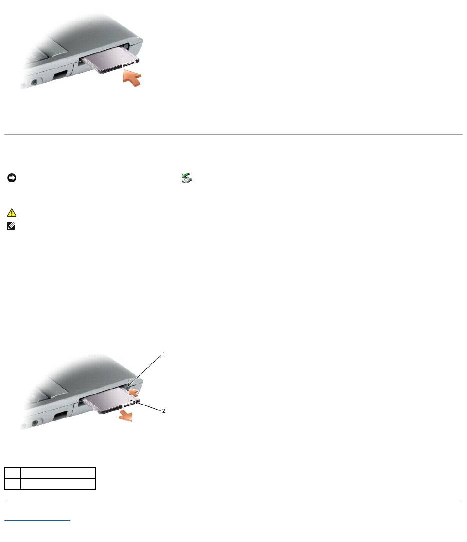
Your computer has two user-accessible SODIMM sockets, one accessed from beneath the keyboard (DIMM A), and the other accessed from the bottom of the
computer (DIMM B).
To add or replace a memory module in the DIMM A connector:
1. Follow the procedures in "Before You Begin."
2. Remove the keyboard.
NOTICE: To disconnect a network cable, first unplug the cable from your computer and then unplug it from the network wall jack.
NOTICE: To avoid damaging the system board, you must remove the main battery before you service the computer.
CAUTION: Before you begin any of the procedures in this section, follow the safety instructions in the Product Information Guide.
NOTICE: If your computer has only one memory module, install the memory module in the connector labeled "DIMMA."
NOTICE: If you remove your original memory modules from the computer during a memory upgrade, keep them separate from any new modules that
you may have, even if you purchased the new modules from Dell. If possible, do not pair an original memory module with a new memory module.
Otherwise, your computer may not function at optimal performance.
NOTE: Memory modules purchased from Dell are covered under your computer warranty.
1
memory module (DIMM A)
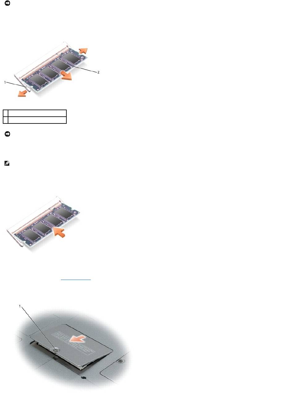
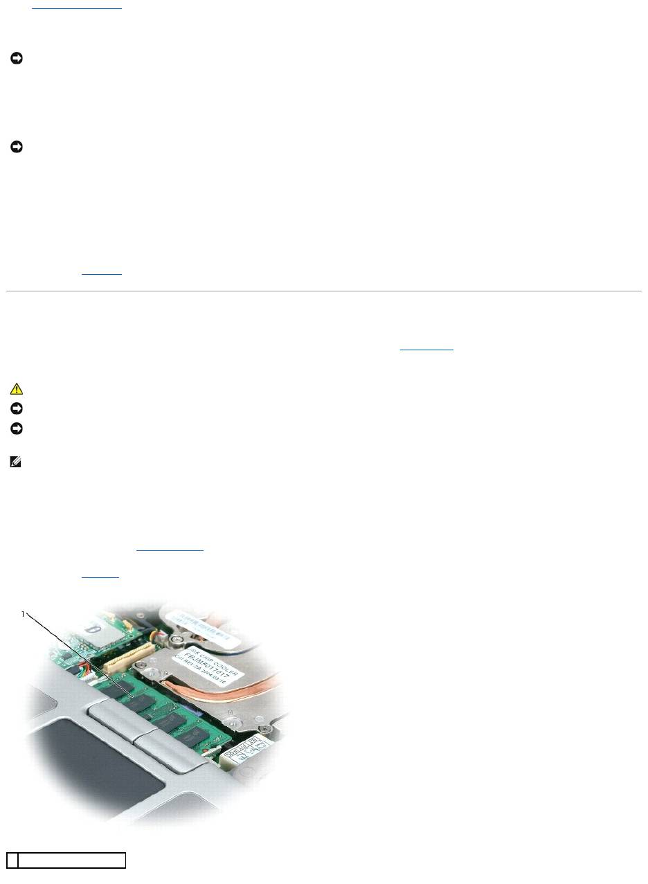
3. If you are replacing a memory module, ground yourself and remove the existing module:
a. Use your fingertips to carefully spread apart the securing clips on each end of the memory module connector until the module pops up.
b. Remove the module from the connector.
4. Ground yourself and install the new memory module:
a. Align the notch in the module edge connector with the tab in the connector slot.
b. Slide the module firmly into the slot at a 45-degree angle, and rotate the module down until it clicks into place. If you do not feel the click, remove
the module and reinstall it.
To add or replace a memory module in the DIMM B connector:
1. Follow the procedures in "Before You Begin."
2. Turn the computer over, loosen the captive screw in the memory module cover, and then remove the cover.
NOTICE: To prevent damage to the memory module connector, do not use tools to spread the memory-module securing clips.
1
securing clips (2 per connector)
2
memory module
NOTICE: If you need to install memory modules in two connectors, install a memory module in the connector labeled "DIMMA" before you install a
module in the connector labeled "DIMMB." Insert memory modules at a 45-degree angle to avoid damaging the connector.
NOTE: If the memory module is not installed properly, the computer may not boot properly. No error message indicates this failure.
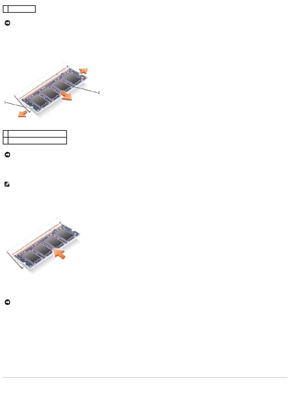
3. If you are replacing a memory module, ground yourself and remove the existing module:
a. Use your fingertips to carefully spread apart the securing clips on each end of the memory module connector until the module pops up.
b. Remove the module from the connector.
4. Ground yourself and install the new memory module:
a. Align the notch in the module edge connector with the tab in the connector slot.
b. Slide the module firmly into the slot at a 45-degree angle, and rotate the module down until it clicks into place. If you do not feel the click, remove
the module and reinstall it.
5. Replace the cover.
6. Insert the battery into the battery bay, or connect the AC adapter to your computer and an electrical outlet.
7. Turn on the computer.
As the computer boots, it detects the additional memory and automatically updates the system configuration information.
To confirm the amount of memory installed in the computer:
®
®
l In the Microsoft
Windows
XP operating system, click the Start button, click Help and Support, and then click Computer Information.
l In Windows 2000, right-click the My Computer icon on your desktop, and then click the General tab.
Modem
1
captive screw
NOTICE: To prevent damage to the memory module connector, do not use tools to spread the memory-module securing clips.
1
securing clips (2 per connector)
2
memory module
NOTICE: If you need to install memory modules in two connectors, install a memory module in the connector labeled "DIMMA" before you install a
module in the connector labeled "DIMMB." Insert memory modules at a 45-degree angle to avoid damaging the connector.
NOTE: If the memory module is not installed properly, the computer may not boot properly. No error message indicates this failure.
NOTICE: If the cover is difficult to close, remove the module and reinstall it. Forcing the cover to close may damage your computer.
If you ordered the optional modem at the same time that you ordered your computer, the modem is already installed
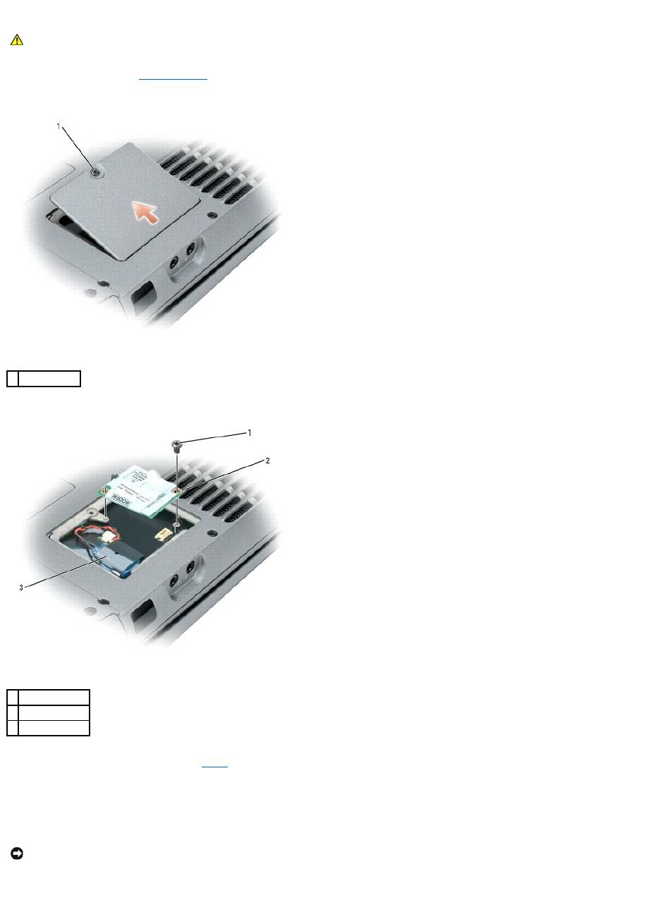
1. Follow the procedures in "Before You Begin."
2. Turn the computer over and release the captive screw from the modem cover.
3. Place your finger under the cover at the indentation and lift the cover open.
4. If a modem is not already installed, go to step5. If you are replacing a modem, remove the existing modem:
a. Remove the screws securing the modem to the system board, and set them aside.
b. Pull straight up on the attached pull-tab to lift the modem out of its connector on the system board, and disconnect the modem cable.
5. Connect the modem cable to the modem.
6. Align the modem with the screw holes and press the modem into the connector on the system board.
CAUTION: Before you begin any of the procedures in this section, follow the safety instructions in the Product Information Guide.
1
captive screw
1
screw
2
modem
3
coin-cell battery
NOTICE: The connectors are keyed to ensure correct insertion. If you feel resistance, check the connectors and realign the card.
7. Install the screws to secure the modem to the system board.
8. Replace the cover.
Mini PCI Card
If you ordered a Mini PCI card with your computer, the card is already installed.
1. Follow the procedures in "Before You Begin."
2. Remove the keyboard.
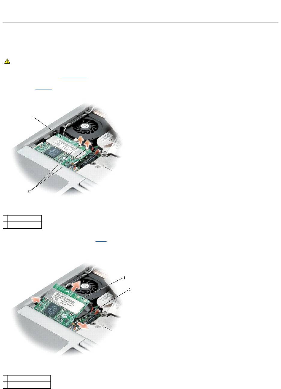
3. If a Mini PCI card is not already installed, go to step4. If you are replacing a Mini PCI card, remove the existing card:
a. Disconnect the Mini PCI card from any attached cables.
CAUTION: Before you begin any of the procedures in this section, follow the safety instructions in the Product Information Guide.
1
Mini PCI card
2
antenna wires (2)
1
Mini PCI card
2
metal securing tabs (2)
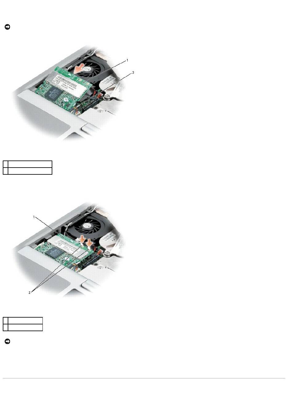
b. Release the Mini PCI card by spreading the metal securing tabs until the card pops up slightly.
c. Lift the Mini PCI card out of its connector.
4. Align the Mini PCI card with the connector at a 45-degree angle, and press the Mini PCI card into the connector until you feel a click.
5. Connect the antenna cables to the Mini PCI card.
6. Replace the cover and screws.
Hard Drive
NOTICE: The connectors are keyed to ensure correct insertion. If you feel resistance, check the connectors and realign the card.
1
Mini PCI card
2
metal securing tabs (2)
1
Mini PCI card
2
antenna wires (2)
NOTICE: To avoid damaging the Mini PCI card, never place cables on top of or under the card.
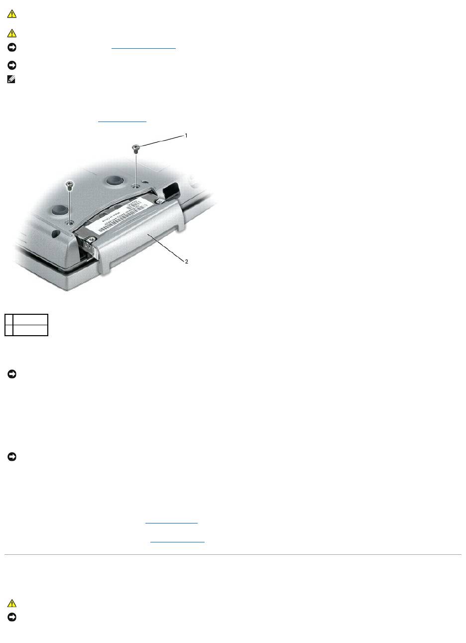
To replace the hard drive in the hard drive bay:
1. Follow the procedures in "Before You Begin."
2. Turn the computer over, and remove the hard drive screws.
3. Slide the hard drive out of the computer.
4. Remove the new drive from its packaging.
Save the original packaging for storing or shipping the hard drive.
5. Slide the hard drive into the bay until it is fully seated.
6. Replace and tighten the screws.
7. Use the Operating System CD to install the operating system for your computer.
8. Use the Drivers and Utilities CD to install the drivers and utilities for your computer.
Keyboard
CAUTION: If you remove the hard drive from the computer when the drive is hot, do not touch the metal housing of the hard drive.
CAUTION: Before working inside your computer, follow the safety instructions in the Product Information Guide.
NOTICE: To prevent data loss, turn off your computer before removing the hard drive. Do not remove the hard drive while the computer is on, in
standby mode, or in hibernate mode.
NOTICE: Hard drives are extremely fragile; even a slight bump can damage the drive.
NOTE: Dell does not guarantee compatibility or provide support for hard drives from sources other than Dell.
1
screws (2)
2
hard drive
NOTICE: When the hard drive is not in the computer, store it in protective antistatic packaging. See "Protecting Against Electrostatic Discharge" in the
Product Information Guide.
NOTICE: Use firm and even pressure to slide the drive into place. If you use excessive force, you may damage the connector.
CAUTION: Before performing the following procedures, read the safety instructions in your Product Information Guide.
NOTICE: To avoid electrostatic discharge, ground yourself by using a wrist grounding strap or by periodically touching an unpainted metal surface (such
as the back panel) on the computer.
