Dell Precision 490 Desktop – страница 2
Инструкция к Компьютеру Dell Precision 490 Desktop
Оглавление
- Примечания, предупреждения и важная информация Сокращения и акронимы
- Содержание
- Поиск информации Возможные направления поиска Где искать
- Возможные направления поиска Где искать
- Возможные направления поиска Где искать
- Возможные направления поиска Где искать
- Установка компьютера (вертикальное положение корпуса) 1 2
- 3
- Видеоплата для подключения одного и двух мониторов, с одним разъемом VGA-адаптер с дуальным Y-кабелем DVI-адаптер с дуальным Y-кабелем
- Видеоплата для подключения двух мониторов, с одним DVI- и одним VGA-разъемом Видеоплата для подключения двух мониторов, с двумя DVI-разъемами
- 4 5
- 6 Установка компьютера (горизонтальное положение корпуса) 1
- 2 3
- Видеоплата для подключения одного и двух мониторов, с одним разъемом VGA-адаптер с дуальным Y-кабелем DVI-адаптер с дуальным Y-кабелем
- Видеоплата для подключения двух мониторов, с одним DVI- и одним VGA-разъемом Видеоплата для подключения двух мониторов, с двумя DVI-разъемами
- 4 5 6
- О компьютере Вид спереди (вертикальное положение корпуса)
- 13 индикаторы диагностики (4)
- Вид сзади (вертикальное положение корпуса)
- Разъемы задней панели
- 11 разъем последовательного порта
- Вид спереди (горизонтальное положение корпуса)
- 13 Индикаторы диагностики (4)
- Вид сзади (горизонтальное положение корпуса)
- Вид изнутри
- Вид изнутри — повернутый отсек для жесткого диска
- Элементы системной платы
- Цвета кабелей
- Дополнительная информация, содержащаяся в руководстве пользователя Снятие крышки корпуса компьютера 1 2
- 3 4 5 6 7
- Уход за компьютером Решение проблем Советы по устранению неполадок Несовместимость программного и аппаратного обеспечения
- Восстановление системы в Microsoft Создание точки восстановления Восстановление более раннего работоспособного состояния компьютера
- Отмена последнего восстановления системы Включение функции System Restore Использование последней работоспособной конфигурации
- Другие возможности решения конфликтов аппаратного и программного обеспечения Программа Dell Diagnostics Когда использовать программу Dell Diagnostics
- Запуск программы Dell Diagnostics с жесткого диска Запуск программы Dell Diagnostics с компакт-диска Drivers and Utilities
- Перед началом тестирования Звуковые коды Код Причина
- Код Причина Сообщения об ошибках
- Индикаторы диагностики Коды индикаторов диагностики перед выполнением теста POST Индикаторы диагностики
- Индикаторы диагностики
- Индикаторы диагностики Сигналы диагностических светодиодов во время процедуры POST Светодиоды Описание проблемы Варианты решения
- Светодиоды Описание проблемы Варианты решения
- Светодиоды Описание проблемы Варианты решения
- Часто задаваемые вопросы Как сделать... Решение Источник информации
- Как сделать... Решение Источник информации
- Индекс
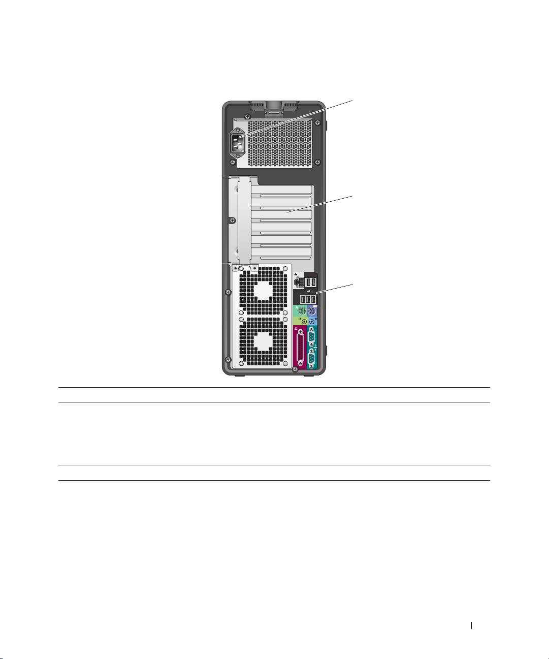
Back View (Tower Orientation)
1
2
3
1 power connector Insert the power cable.
2 card slots Access connectors for any installed PCI, PCI-X, or PCI Express cards.
NOTE: The center four slots support full-length cards: one PCI-X slot, one PCI
Express x8 slot (wired as x4), one PCI Express x16 slot, and one PCI slot); and the top
and bottom slots support half-length cards: one PCI-X slot and one PCI Express x8
slot (wired as x4).
3 back panel connectors Plug serial, USB, and other devices into the
appropriate connectors
.
Quick Reference Guide 21
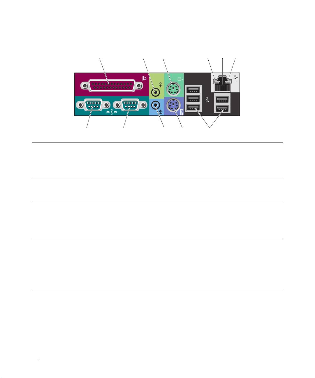
Back Panel Connectors
1 parallel connector Connect a parallel device, such as a printer, to the parallel connector. If you have
a USB printer, plug it into a USB connector.
NOTE: The integrated parallel connector is automatically disabled if the computer
detects an installed card containing a parallel connector configured to the same
address. For more information, see your User’s Guide.
2 line-out/ headphone
Use the green line-out connector to attach headphones and most speakers with
connector
integrated amplifiers.
On computers with a sound card, use the connector on the card.
3 PS/2 mouse connector Plug a standard mouse into the green mouse connector. Turn off the computer
and any attached devices before you connect a mouse to the computer. If you
have a USB mouse, plug it into a USB connector.
®
®
If your computer is running the Microsoft
Windows
XP operating system,
the necessary mouse drivers have been installed on your hard drive.
4 link integrity light
• Green — A good connection exists between a 10-Mbps network and
the computer.
• Orange — A good connection exists between a 100-Mbps network and
the computer.
• Yellow — A good connection exists between a 1000-Mbps (or 1-Gbps) network
and the computer.
• Off — The computer is not detecting a physical connection to the network.
22 Quick Reference Guide
1 23 5
11 10 9 8 7
46

5 network adapter
To attach your computer to a network or broadband device, connect one end
connector
of a network cable to either a network jack or your network or broadband device.
Connect the other end of the network cable to the network adapter connector
on your computer. A click indicates that the network cable has been
securely attached.
NOTE: Do not plug a telephone cable into the network connector.
On computers with an additional network connector card, use the connectors
on the card and on the back of the computer when setting up multiple network
connections (such as a separate intra- and extranet).
It is recommended that you use Category 5 wiring and connectors for your
network. If you must use Category 3 wiring, force the network speed to 10 Mbps
to ensure reliable operation.
6 network activity light Flashes a yellow light when the computer is transmitting or receiving network
data. A high volume of network traffic may make this light appear to be in a
steady "on" state.
7 USB 2.0 connectors (5) It is recommended that you use the front USB connectors for devices that you
connect occasionally, such as flash memory keys or cameras, or for bootable
USB devices.
Use the back USB connectors for devices that typically remain connected,
such as printers and keyboards.
8 PS/2 keyboard connector If you have a standard keyboard, plug it into the purple keyboard connector.
If you have a USB keyboard, plug it into a USB connector.
9 line-in connector Use the blue line-in connector to attach a record/playback device such
as a cassette player, CD player, or VCR.
On computers with a sound card, use the connector on the card.
10 serial connector Connect a serial device, such as a handheld device, to the serial port. If necessary,
the address for this port can be modified through system setup. See your
User’s Guide for more information.
11 serial connector Connect a serial device, such as a handheld device, to the serial port. If necessary,
the address for this port can be modified through system setup. See your
User’s Guide for more information.
Quick Reference Guide 23
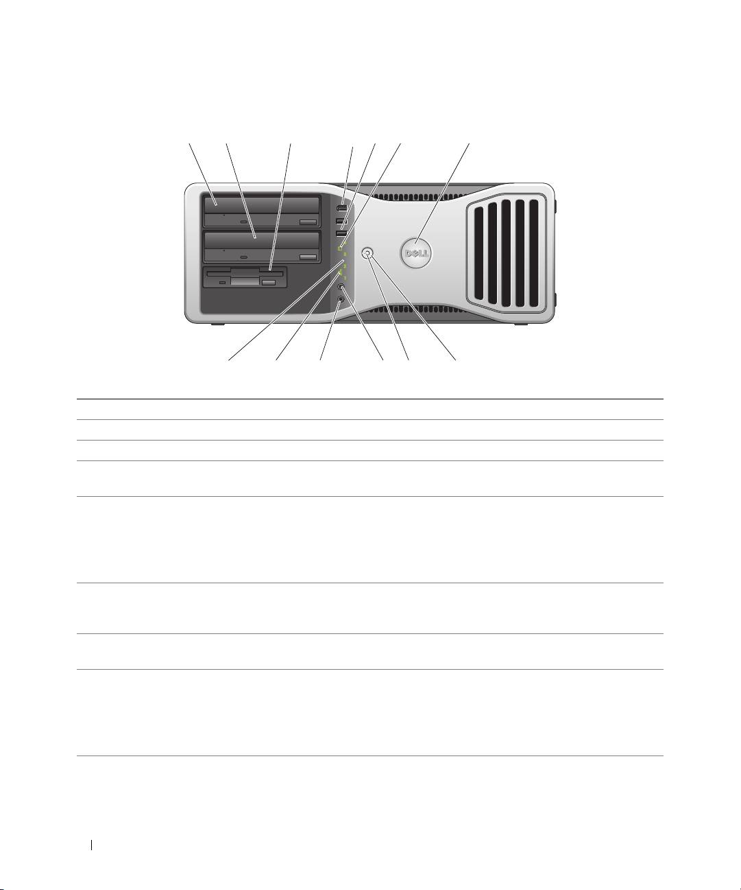
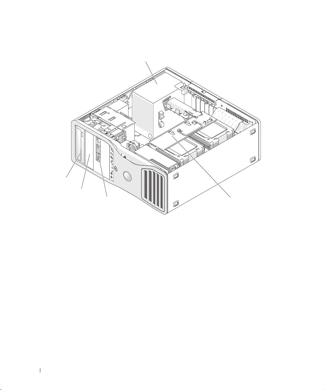
Front View (Desktop Orientation)
1 23 56 7
4
910111213
8
1 upper 5.25-inch drive bay Holds a CD/DVD drive.
2 lower 5.25-inch drive bay You can use the bay for an optional CD/DVD drive, or a SATA hard drive.
3 FlexBay You can use the bay for a floppy drive, or a Media Card Reader.
4 IEEE 1394 connector
Use the optional IEEE 1394 connector for high-speed data devices such as digital
(optional)
video cameras and external storage devices.
5 USB 2.0 connectors (2) Use the front USB connectors for devices that you connect occasionally, such as
flash memory keys or cameras, or for bootable USB devices (see
"System Setup"
in your
User’s Guide
for more information on booting to a USB device).
It is recommended that you use the back USB connectors for devices that
typically remain connected, such as printers and keyboards.
6 hard-drive activity light The hard drive light is on when the computer reads data from or writes data to
the hard drive. The light might also be on when a device such as your CD player
is operating.
7 Dell™ rotatable badge To rotate the Dell badge for tower-to-desktop conversion; remove the
front panel
,
turn it over, and rotate the plastic handle behind the badge.
8 power button Press to turn on the computer.
NOTICE: To avoid losing data, do not use the power button to turn off the computer.
Instead, perform an operating system shutdown.
NOTE: The power button can also be used to wake the system or to place it into
a power-saving state. See your User’s Guide for more information.
24 Quick Reference Guide
9 power light The power light illuminates and blinks or remains solid to indicate
different states:
• No light — The computer is turned off.
• Steady green — The computer is in a normal operating state.
• Blinking green — The computer is in a power-saving state.
• Blinking or solid amber — See "Power Problems" in your
User’s Guide
.
To exit from a power-saving state, press the power button or use the keyboard or
the mouse if it is configured as a wake device in the Windows Device Manager.
For more information about sleep states and exiting from a power-saving state,
see your User’s Guide.
See "Diagnostic Lights" on page 38 for a description of light codes that can help
you troubleshoot problems with your computer.
10 headphone connector Use the headphone connector to attach headphones.
11 microphone connector Use the microphone connector to attach a personal computer microphone for
voice or musical input into a sound or telephony program.
12 network link light The network link light is on when a good connection exists between a 10-Mbps,
100-Mbps, or 1000-Mbps (or 1-Gbps) network and the computer.
13 diagnostic lights (4) Use these lights to help you troubleshoot a computer problem based on the
diagnostic code. For more information, see "Diagnostic Lights" on page 38.
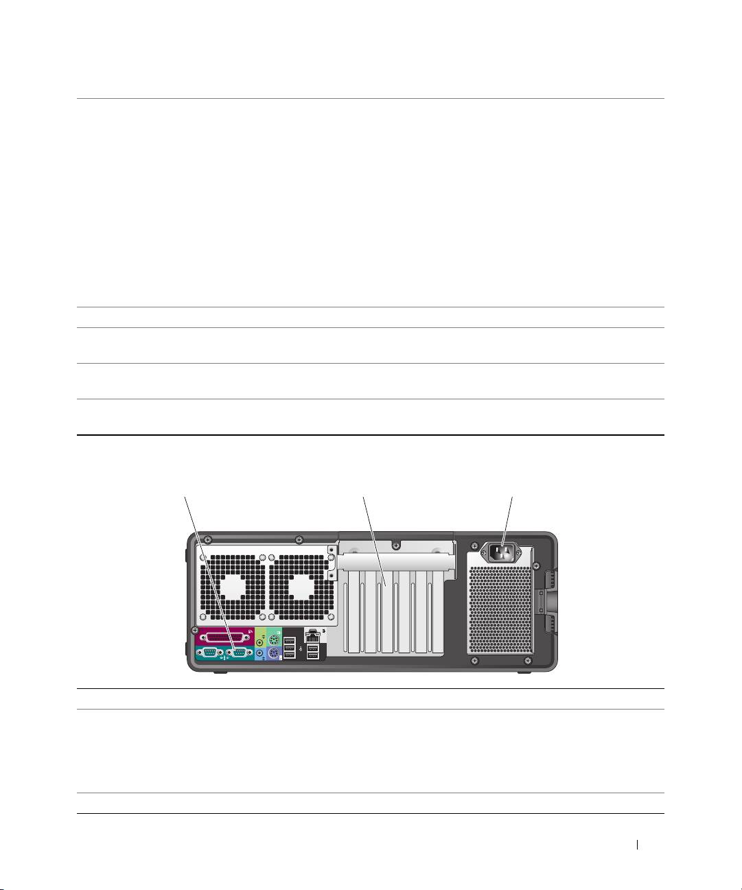
Back View (Desktop Orientation)
1 2 3
1 back panel connectors Plug serial, USB, and other devices into the
appropriate connector
.
2 card slots Access connectors for any installed PCI, PCI-X, or PCI Express cards.
NOTE:
The slot farthest to the left and the two slots on the right support half-length
cards: one PCI Express x8 slot (wired as x4) and two PCI-X slots. The center three slots
support full-length cards: one PCI Express x16 slot, one PCI Express x8 slot (wired as x4)
and one PCI slot.
3 power connector Insert the power cable.
Quick Reference Guide 25
Inside View
1
5
4
3
2
1 power supply 2 rotatable hard drive bay 3 FlexBay
4 lower 5.25-inch drive bay 5 upper 5.25-inch drive bay
26 Quick Reference Guide
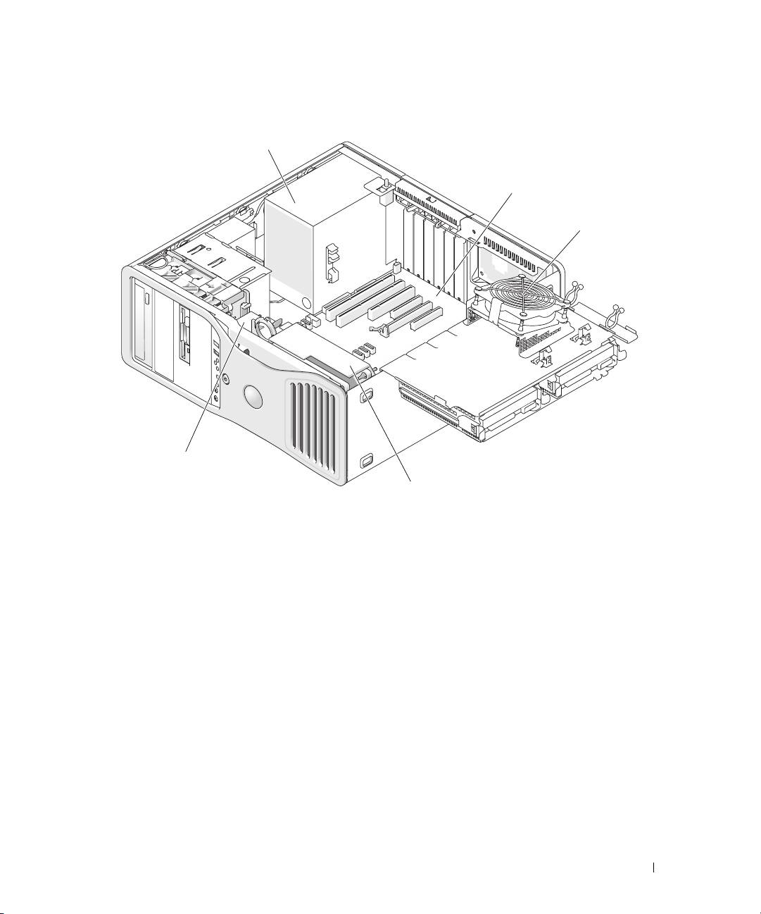
Inside View – Hard Drive Bay Rotated Out
1
2
3
5
4
1 power supply 2 system board 3 memory fan
4 front fan 5 card fan
Quick Reference Guide 27
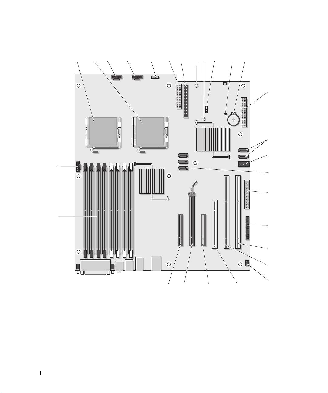
System Board Components
28 Quick Reference Guide
3 4567 12
26
22232425
2
27
10
13
14
15
16
17
19
20
119
18
21
1
8

1 primary processor connector (CPU_0) 15 Flexbay connector (USB)
2 secondary processor connector (CPU_1) 16 SATA connectors (SATA_2, SATA_1, SATA_0)
3 front fan connector (FAN_FRONT) 17 floppy drive (DSKT)
4 card cage fan (FAN_CCAG) 18 front panel connector (FRONTPANEL)
5 internal speaker connector (INT_SPKR) 19 PCI-X card slot (SLOT6_PCIX)
6 power connector (POWER2) 20 PCI-X card slot (SLOT5_PCIX)
7 IDE drive connector (IDE) 21 chassis intrusion header (INTRUDER)
8 standby power light (AUX_PWR) 22 PCI card slot (SLOT4_PCI)
9 password jumper (PSWD) 23 PCI-Express x8 card slot, wired as x4
(SLOT3_PCIE)
10 auxiliary hard-drive LED connector
24 PCI-Express x16 card slot (SLOT2_PCIE)
(AUX_LED)
11 RTC reset jumper (RTCRST) 25 PCI-Express x8 card slot, wired as x4
(SLOT1_PCIE)
12 battery socket (BATTERY)) 26 memory module connectors (DIMM_1-8)
13 main power connector (POWER1) 27 memory fan connector (FAN_MEM)
14 SATA connectors (SATA_4, SATA_3)
Cable Colors
Device Color
SATA Hard drive blue cable
Floppy drive black pull-tab
CD/DVD drive orange pull-tab
front panel yellow pull-tab
Locating Your User’s Guide
Your
User’s Guide
contains additional information about your computer such as:
• Technical specifications
• Information for changing the orientation of your computer from a desktop to a tower
• Front and back views of your computer, including all of the available connectors
• Inside views of your computer, including a detailed graphic of the system board and the connectors
• Instructions for cleaning your computer
• Information on software features, such as Legacy Select Technology control, using a password,
and system setup options
Quick Reference Guide 29

• Tips and information for using the Microsoft Windows XP operating system
• Instructions for removing and installing parts, including memory, cards, drives, the microprocessor,
and the battery
• Information for troubleshooting various computer problems
• Instructions for using the Dell Diagnostics and reinstalling drivers
• Information on how to contact Dell
You can access the
User’s Guide
from your hard drive or the Dell Support website at
support.dell.com
.
Removing the Computer Cover
CAUTION: Before you begin any of the procedures in this section, follow the safety instructions in the
Product Information Guide.
CAUTION: To guard against electrical shock, always unplug your computer from the electrical outlet before
removing the cover.
NOTICE: To prevent static damage to components inside your computer, discharge static electricity from your
body before you touch any of your computer’s electronic components. You can do so by touching an unpainted
metal surface on the computer.
1
Follow the procedures in "Before You Begin" in your
User’s Guide
.
NOTICE: Opening the computer cover while the computer is running could result in a shutdown without warning
and a loss of data in open programs. The computer cooling system cannot function properly while the cover
is removed.
2
If you have installed a security cable, remove it from the security cable slot.
NOTICE: Ensure that sufficient space exists to support the removed cover—at least 30 cm (1 ft) of desk top space.
NOTICE: Ensure that you are working on a level, protected surface to avoid scratching either the computer or the
surface on which it is resting.
3
Lay your computer on a flat surface with the cover facing up.
30 Quick Reference Guide
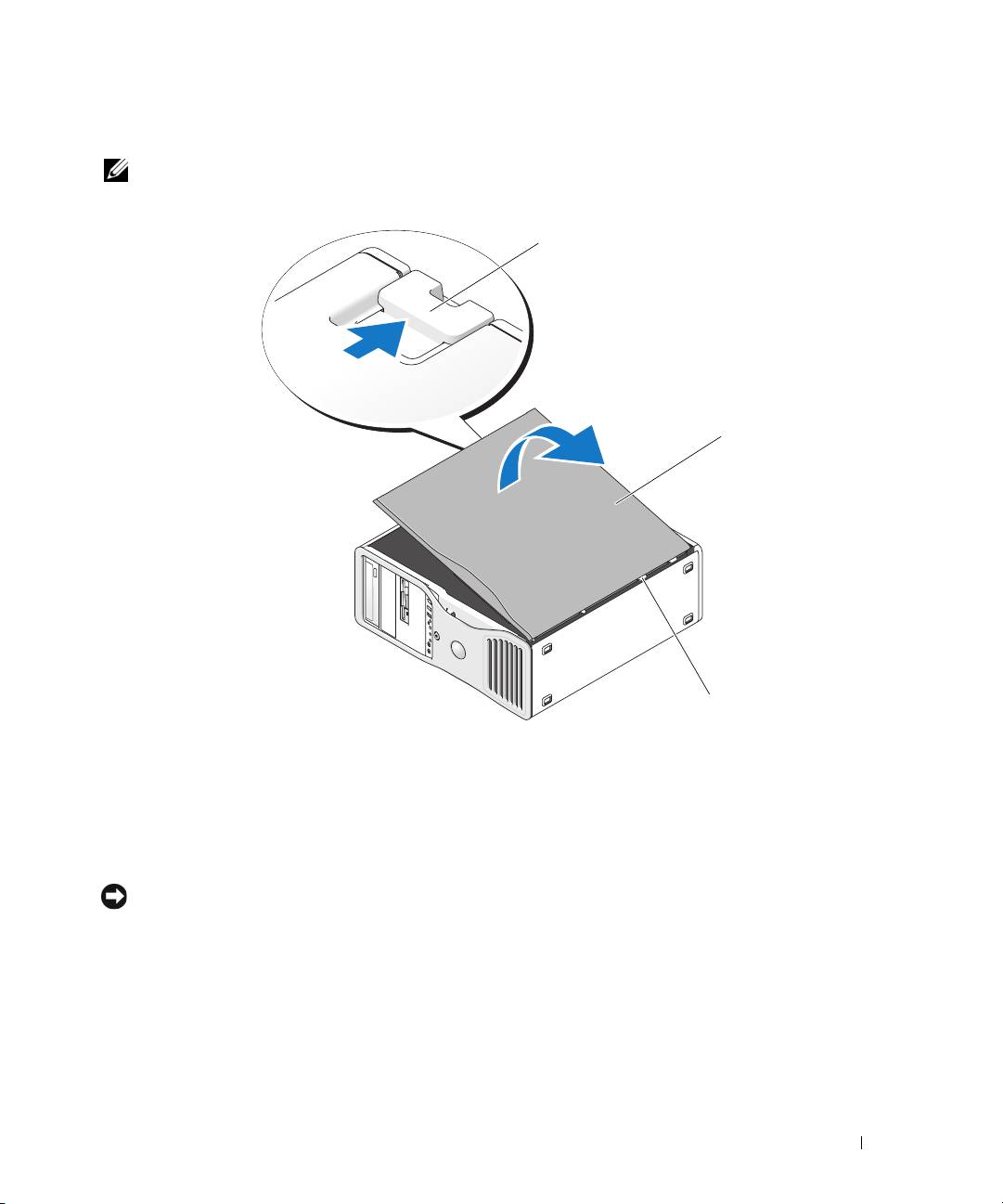
4
Pull back the cover latch release.
NOTE: The computer in the following images is configured as a tower computer. See "Changing Between Tower
and Desktop Modes" in your User’s Guide for information regarding computer orientation.
1
2
3
1
cover latch release
2
computer cover
3
cover hinges
5
Locate the three hinge tabs on the edge of the computer.
6
Grip the sides of the computer cover and pivot the cover up, using the hinges as leverage points.
7
Release the cover from the hinge tabs and set it aside in a secure location.
NOTICE: The computer cooling system cannot function properly while the computer cover is not installed.
Do not attempt to boot the computer before replacing the computer cover.
Quick Reference Guide 31

Caring for Your Computer
To help maintain your computer, follow these suggestions:
• To avoid losing or corrupting data, never turn off your computer when the hard drive light is on.
• Schedule regular virus scans using virus software.
• Manage hard drive space by periodically deleting unnecessary files and defragmenting the drive.
• Back up files on a regular basis.
• Periodically clean your monitor screen, mouse, and keyboard (see your
User’s Guide
for more information).
Solving Problems
Troubleshooting Tips
Perform the following checks when you troubleshoot your computer:
• If you added or removed a part before the problem started, review the installation procedures
and ensure that the part is correctly installed.
• If a peripheral device does not work, ensure that the device is properly connected.
• If an error message appears on the screen, write down the exact message. The message may help
technical support personnel diagnose and fix the problem(s).
• If an error message occurs in a program, see the program’s documentation.
• If the recommended action in the troubleshooting section is to see a section in your
User’s Guide
,
go to
support.dell.com
(on another computer if necessary) to access your
User’s Guide.
Resolving Software and Hardware Incompatibilities
If a device is either not detected during the operating system setup or is detected but incorrectly configured,
you can use the Hardware Troubleshooter to resolve the incompatibility.
To resolve incompatibilities using the Hardware Troubleshooter:
1
Click the
Start
button and click
Help and Support
.
2
Ty p e
hardware troubleshooter
in the
Search
field and click the arrow to start the search.
3
Click
Hardware Troubleshooter
in the
Search Results
list.
4
In the
Hardware Troubleshooter
list, click
I need to resolve a hardware conflict on my computer
,
and click
Next
.
32 Quick Reference Guide

®
®
Using Microsoft
Windows
XP System Restore
The Microsoft Windows XP operating system provides System Restore to allow you to return your
computer to an earlier operating state (without affecting data files) if changes to the hardware, software,
or other system settings have left the computer in an undesirable operating state. See the Windows Help
and Support Center for information about using System Restore (see "Finding Information" on page 5
for information about accessing the Windows Help and Support Center).
NOTICE: Make regular backups of your data files. System Restore does not monitor your data files or recover them.
Creating a Restore Point
1
Click the
Start
button and click
Help and Support
.
2
Click
System Restore
.
3
Follow the instructions on the screen.
Restoring the Computer to an Earlier Operating State
NOTICE: Before you restore the computer to an earlier operating state, save and close any open files and exit any
open programs. Do not alter, open, or delete any files or programs until the system restoration is complete.
1
Click the
Start
button, point to
All Programs
→
Accessories
→
System Tools
, and then click
System Restore
.
2
Ensure that
Restore my computer to an earlier time
is selected and click
Next
.
3
Click a calendar date to which you want to restore your computer.
The
Select a Restore Point
screen provides a calendar that allows you to see and select restore points.
All calendar dates with available restore points appear in boldface type.
4
Select a restore point and click
Next
.
If a calendar date has only one restore point, then that restore point is automatically selected.
If two or more restore points are available, click the restore point that you prefer.
5
Click
Next
.
The
Restoration Complete
screen appears after System Restore finishes collecting data
and then the computer restarts.
6
After the computer restarts, click
OK
.
To change the restore point, you can either repeat the steps using a different restore point, or you can
undo the restoration.
Quick Reference Guide 33

Undoing the Last System Restore
NOTICE: Before you undo the last system restore, save and close all open files and exit any open programs.
Do not alter, open, or delete any files or programs until the system restoration is complete.
1
Click the
Start
button, point to
All Programs
→
Accessories
→
System Tools
, and then click
System Restore
.
2
Click
Undo my last restoration
and click
Next
.
3
Click
Next
.
The
System Restore
screen appears and the computer restarts.
4
After the computer restarts, click
OK
.
Enabling System Restore
If you reinstall Windows XP with less than 200 MB of free hard-disk space available, System Restore
is automatically disabled. To see if System Restore is enabled:
1
Click the
Start
button and click
Control
Panel
.
2
Click
Performance and Maintenance
.
3
Click
System
.
4
Click the
System Restore
tab.
5
Ensure that
Turn off System Restore
is unchecked.
Using the Last Known Good Configuration
1
Restart your computer and press <F8> when the message
Please select the operating
system to start
appears.
2
Highlight
Last Known Good Configuration
, press <Enter>, press <l>, and then select your
operating system when prompted.
Other Options to Help Resolve Additional Device or Software Conflicts
NOTICE: The following processes erase all of the information on your hard drive.
• Reinstall your operating system using the operating system installation guide and
Operating System
CD.
During the operating system reinstallation, you can select to delete the existing partitions and reformat
your hard drive.
• Reinstall all drivers, beginning with the chipset, using the
Drivers and Utilities
CD
.
34 Quick Reference Guide

Dell Diagnostics
CAUTION: Before you begin any of the procedures in this section, follow the safety instructions
in the Product Information Guide.
When to Use the Dell Diagnostics
If you experience a problem with your computer, perform the checks in "Solving Problems" on page 32
and run the Dell Diagnostics before you contact Dell for technical assistance.
It is recommended that you print these procedures before you begin.
NOTICE: The Dell Diagnostics works only on Dell™ computers. Using this program with other computers
can cause incorrect computer responses or result in error messages.
The Dell Diagnostics allow you to:
• Perform quick checks or extensive tests on one or all devices
• Choose how many times a test is run
• Display or print test results or save them in a file
• Suspend testing if an error is detected or terminate testing if a certain number of errors occur
• Access online
Help
screens that describe the tests and how to run them
• Read status messages that tell you whether tests completed successfully
• Receive error messages if problems are detected
Starting the Dell Diagnostics From Your Hard Drive
1
Turn on (or restart) your computer.
2
When the DELL™ logo appears, press <F12> immediately.
NOTE: If you see a message stating that no diagnostics utility partition has been found, see "Starting
the Dell Diagnostics From the Drivers and Utilities CD" in your User’s Guide
If you wait too long and the operating system logo appears, continue to wait until you see the
Microsoft Windows desktop. Then shut down your computer and try again. For more information
on shutting down your computer, see your
User’s Guide.
3
When the boot device list appears, highlight
Boot to Utility Partition
and press <Enter>.
4
When the Dell Diagnostics
Main Menu
appears, select the test you want to run. For more information
on the tests, see your
User’s Guide.
Quick Reference Guide 35

Starting the Dell Diagnostics From the Drivers and Utilities CD
1
Insert the
Drivers and Utilities
CD.
2
Shut down and restart the computer.
When the DELL logo appears, press <F12> immediately.
If you wait too long and the Windows logo appears, continue to wait until you see the Windows
desktop. Then shut down your computer and try again.
NOTE: The next steps change the boot sequence for one time only. On the next start-up, the computer boots
according to the devices specified in the system setup program.
3
When the boot device list appears, highlight
Onboard or USB CD-ROM Drive
and press <Enter>.
4
Select the
Boot from CD-ROM
option from the menu that appears and press <Enter>.
5
Ty p e
1
to start the menu and press <Enter> to proceed.
6
Select
Run the 32 Bit Dell Diagnostics
from the numbered list. If multiple versions are listed,
select the version appropriate for your computer.
7
When the Dell Diagnostics
Main Menu
appears, select the test you want to run.
Before You Start Testing
CAUTION: Before you begin any of the procedures in this section, follow the safety instructions in the
Product Information Guide.
• Turn on your printer if one is attached.
• Enter system setup, review your computer’s configuration information, and enable all of your
computer’s components and devices, such as connectors.
Beep Codes
Your computer might emit a series of beeps during start-up if the monitor cannot display errors or problems.
This series of beeps, called a beep code, identifies a problem. One possible beep code (code 1-3-1)
consists of one beep, a burst of three beeps, and then one beep. This beep code tells you that the
computer encountered a memory problem.
If your computer beeps during start-up:
1
Write down the beep code on the "Diagnostics Checklist" in your
User’s Guide
.
2
Run the Dell Diagnostics to identify a more serious cause.
3
Contact Dell for technical assistance.
36 Quick Reference Guide

Code Cause
1-1-2 Microprocessor register failure
1-1-3 NVRAM read/write failure
1-1-4 ROM BIOS checksum failure
1-2-1 Programmable interval timer failure
1-2-2 DMA initialization failure
1-2-3 DMA page register read/write failure
1-3 Video Memory Test failure
1-3-1 through 2-4-4 Memory not being properly identified or used
1-3-2 Memory problem
3-1-1 Slave DMA register failure
3-1-2 Master DMA register failure
3-1-3 Master interrupt mask register failure
3-1-4 Slave interrupt mask register failure
3-2-2 Interrupt vector loading failure
3-2-4 Keyboard Controller Test failure
3-3-1 NVRAM power loss
3-3-2 Invalid NVRAM configuration
3-3-4 Video Memory Test failure
3-4-1 Screen initialization failure
3-4-2 Screen retrace failure
3-4-3 Search for video ROM failure
4-2-1 No timer tick
4-2-2 Shutdown failure
4-2-3 Gate A20 failure
4-2-4 Unexpected interrupt in protected mode
4-3-1 Memory failure above address 0FFFFh
4-3-3 Timer-chip counter 2 failure
4-3-4 Time-of-day clock stopped
4-4-1 Serial or parallel port test failure
4-4-2 Failure to decompress code to shadowed memory
4-4-3 Math-coprocessor test failure
4-4-4 Cache test failure
Quick Reference Guide 37
Error Messages
NOTE: If the message is not listed, see the documentation for either the operating system or the program that was
running when the message appeared.
If an error occurs during start-up, a message may be displayed on the monitor identifying the problem.
See "Error Messages" in your User’s Guide for suggestions on resolving any problems.
Diagnostic Lights
CAUTION: Before you begin any of the procedures in this section, follow the safety instructions in the
Product Information Guide.
To help you troubleshoot a problem, your computer has four lights labeled "1," "2," "3," and "4" on the
front. The lights can be "off" or green. When the computer starts normally, the lights flash. If the
computer malfunctions, the pattern of the lights and also that of the power button help to identify the
problem.These lights also indicate sleep states.
Diagnostic Light Codes Before POST
Diagnostic Lights Power
Problem Description Suggested Resolution
Light
off No electrical power is
Connect the computer to an electrical outlet.
supplied to the computer.
Ensure that the front-panel power light is on.
If the power light is off, ensure that the
computer is connected to a working electrical
outlet and then press the power button.
If the problem is still not resolved, contact
Dell for technical assistance.
off The computer is in a normal
Press the power button to turn the computer on.
off condition; the computer is
If the computer does not turn on, ensure that
connected to an electrical
the front-panel power light is on. If the power
outlet.
light is off, ensure that the computer is
connected to a working electrical outlet and
then press the power button.
If the problem is still not resolved, contact
Dell for technical assistance.
38 Quick Reference Guide

Diagnostic Lights Power
Problem Description Suggested Resolution
Light
blinking
The computer is in a reduced
Use one of the appropriate methods to "wake
green
power or "sleep" state.
up" the computer. See "Advanced Features"
in your User’s Guide.
If the problem is not resolved and you are trying
to wake the computer with a USB mouse or
keyboard, substitute the mouse or keyboard
with a working PS/2 mouse or keyboard and
then try to wake the computer.
amber The BIOS is not executing. Ensure that the processor is seated correctly and
restart the computer. See "Processor" in your
User’s Guide.
(blinking)
If the problem is still not resolved, contact Dell
for technical assistance.
blinking
A possible power supply or
Perform the procedure in "Power Problems"
amber
power cable failure has
in your User’s Guide.
occurred.
If the problem is still not resolved, contact Dell
(blinking)
for technical assistance.
amber A possible system board
Contact Dell for technical assistance.
failure has occurred.
(blinking)
amber A processor mismatch exists. Perform the procedure in "Processor Problems"
in your User’s Guide.
(blinking)
Quick Reference Guide 39

Diagnostic Lights Power
Problem Description Suggested Resolution
Light
amber A possible failure has been
Verify that any required power cables are
detected in a plug-in
connected to the memory and graphics
component such as a graphics
riser cards.
(blinking)
riser card or memory
Perform the procedure in "Power Problems"
riser card.
in your User’s Guide.
amber A possible power supply
Verify that both power supply cables are
failure has occurred.
plugged in to the motherboard.
(blinking)
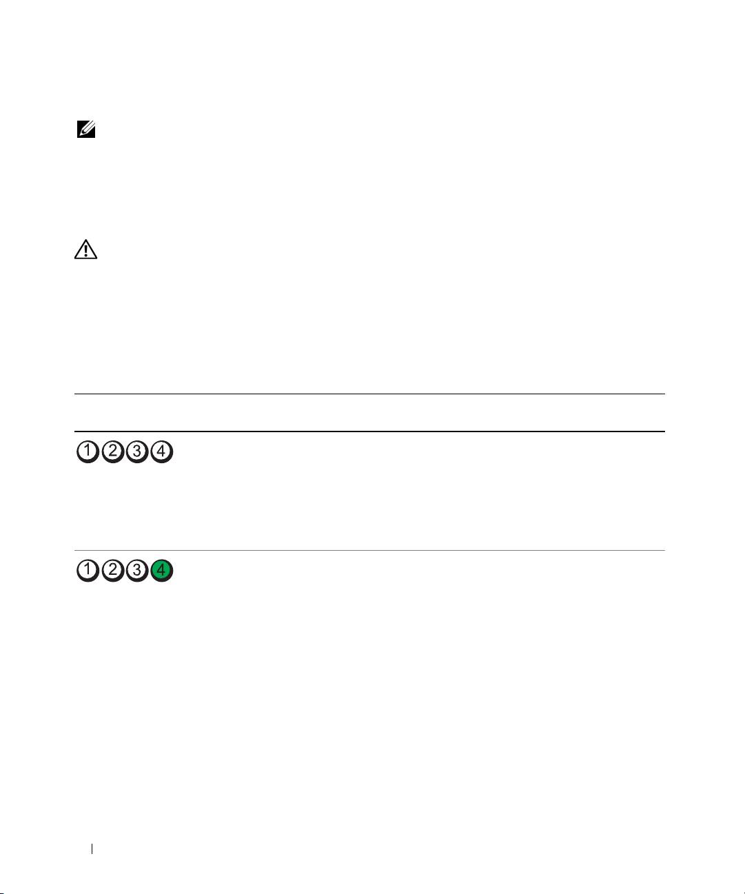
Diagnostic Light Codes During POST
The power light displays a solid green for diagnostic light codes during POST.
Light Pattern Problem Description Suggested Resolution
A possible processor failure has
Reinstall the processor and restart the computer.
occurred.
A possible expansion card failure
1
Determine if a conflict exists by removing a card
has occurred.
(not the graphics card) and then restarting the computer.
2
If the problem persists, reinstall the card that you
removed, remove a different card, and then restart the
computer.
3
Repeat this process for each card. If the computer starts
normally, troubleshoot the last card removed from the
computer for resource conflicts (see "Resolving Software
and Hardware Incompatibilities" on page 32).
4
If the problem persists, contact Dell
.
A possible graphics card failure
1
If the computer has a graphics card, remove the card,
has occurred.
reinstall it, and then restart the computer.
2
If the problem still exists, install a graphics card that
you know works and restart the computer.
3
If the problem persists or the computer has integrated
graphics, contact Dell
.
A possible floppy or hard drive
Reseat all power and data cables and restart the computer.
failure has occurred.
40 Quick Reference Guide
