Dell PowerEdge 860: Jumpers and Connectors
Jumpers and Connectors: Dell PowerEdge 860
Jumpers and Connectors
This section provides specific information about the system jumpers and describes the connectors
on the various boards in the system.
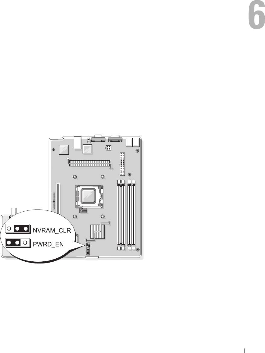
System Board Jumpers
Figure 6-1 shows the location of the configuration jumpers on the system board. Table 6-1 lists the
jumper settings.
Figure 6-1. System Board Jumpers
Jumpers and Connectors 97
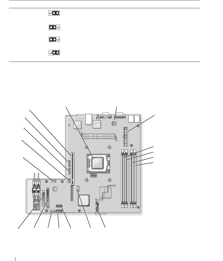
Table 6-1. System Board Jumper Settings
Jumper Setting Description
NVRAM_CLR (default) The configuration settings in NVRAM are retained at system
boot.
The configuration settings in NVRAM are cleared at next
system boot.
PWRD_EN (default) The password feature is enabled.
The password feature is disabled.
System Board Connectors
See Figure 6-2 and Table 6-2 for the location and description of the system board connectors.
Figure 6-2. System Board Connectors
1
2
19
3
18
17
16
4
5
15
6
7
14
13
12 11
10
9 8
98 Jumpers and Connectors

Table 6-2. System Board Connectors
Item Connector Description
1 PROC Processor socket
2 12V power supply connector
3 PWR_CONN power supply connector
4 DIMM 1 Memory module
5 DIMM 3 Memory module
6 DIMM 2 Memory module
7 DIMM 4 Memory module
8 FAN Power connector for the fans
9 BATTERY Connector for the 3.0 V coin battery
10 SATA_0 Connector for the SATA 0 hard drive
11 SATA_1 Connector for the SATA 1 hard drive
12 PCI FAN Connector for the PCI fan
13 FP_CONN1 Control panel interface connector
14 IDE Optical drive interface connector
15 HD_ACT Hard drive activity connector (expansion controller)
16 INTRUSION_SWITCH Connector for the chassis intrusion switch
17 I2C HEADER Remote access controller connector
18 BMC PROG Remote access controller connector
19 RISER_CONN1 Riser card interface connector
Riser Card Connectors
The system is available with either a PCIe riser card or a PCI-X/PCIe riser card. See Figure 6-3 and
Figure 6-4 for the location and description of the expansion-card slots on the two riser cards.
Jumpers and Connectors 99
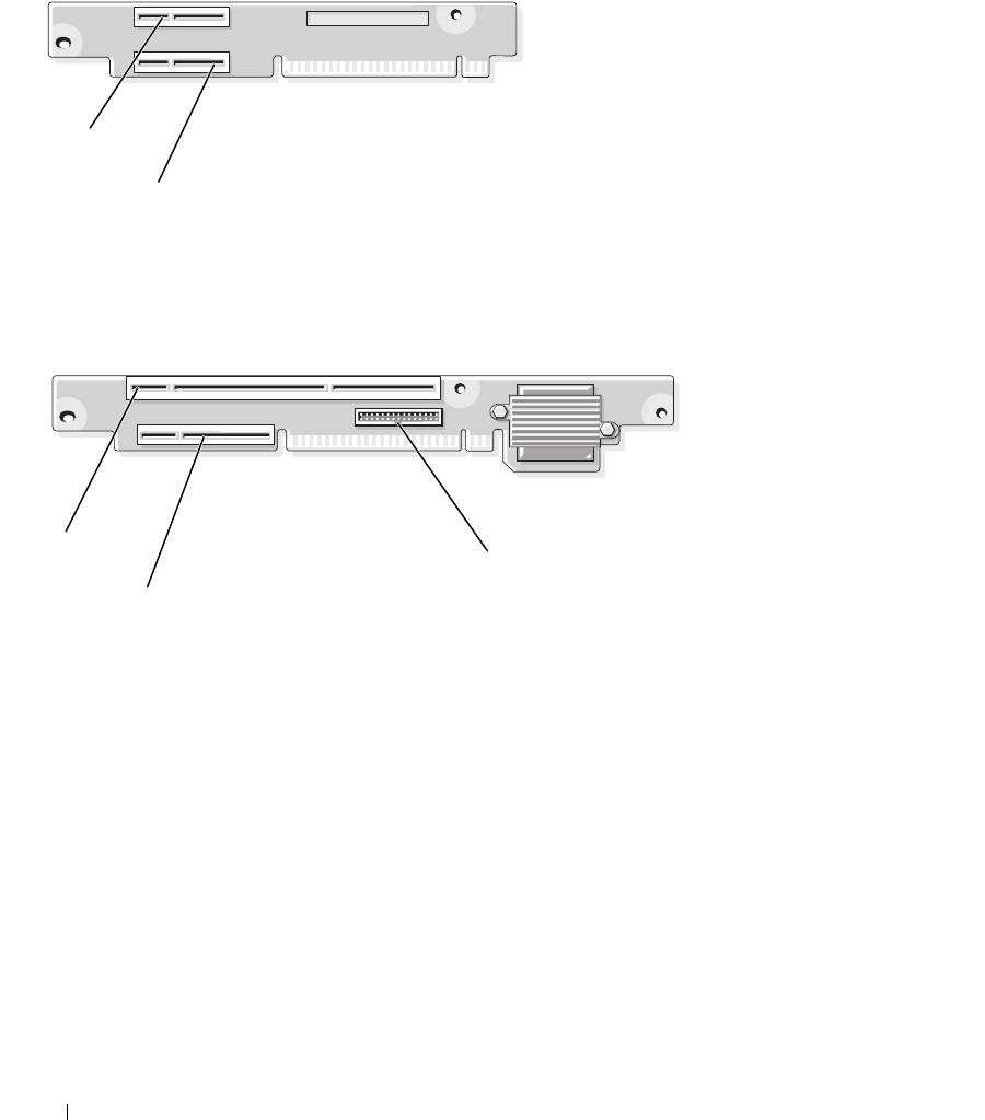
Figure 6-3. PCIe Riser Card Connectors
1
2
1 slot 1, PCIe x4-lane (x8-lane
2 slot 2, PCIe x8-lane
connector)
Figure 6-4. PCI-X/PCIe Riser Card Connectors
1
3
2
1 slot 1, PCI-X 64-bit 133 MHz
2 slot 2, PCIe x8-lane 3 system management
(3.3 V)
100 Jumpers and Connectors

Disabling a Forgotten Password
The system's software security features include a system password and a setup password, which are
discussed in detail in
"Using the System Setup Program
" on page 29. The password jumper enables these
password features or disables them and clears any password(s) currently in use.
CAUTION: Only trained service technicians are authorized to remove the system cover and access any of the
components inside the system. Before performing any procedure, see your Product Information Guide for
complete information about safety precautions, working inside the computer and protecting against electrostatic
discharge.
1
Turn off the system and attached peripherals, and disconnect the system from the electrical outlet.
2
Open the system. See "Opening and Closing the System" on page 44.
3
Remove the password jumper plug.
See Figure 6-1 to locate the password jumper on the system board.
4
Close the system. See "Closing the System" on page 47.
5
Reconnect the system to the electrical outlet, and turn on the system.
The existing passwords are not disabled (erased) until the system boots with the password jumper plug
removed. However, before you assign a new system and/or setup password, you must install the jumper
plug.
NOTE: If you assign a new system and/or setup password with the jumper plug still removed, the system
disables the new password(s) the next time it boots.
6
Turn off the system, including any attached peripherals, and disconnect the system from the electrical
outlet.
7
Open the system.
8
Install the password jumper plug.
See Figure 6-1 to locate the password jumper on the system board.
9
Close the system, reconnect the system to the electrical outlet, and turn on the system.
10
Assign a new system and/or setup password.
To assign a new password using the System Setup program, see "Using the System Setup Program" on
page 29.
Jumpers and Connectors 101

102 Jumpers and Connectors
