Dell POWEREDGE M1000E: инструкция
Раздел: Бытовая, кухонная техника, электроника и оборудование
Тип: Компьютерные аксессуары
Инструкция к Компьютерным аксессуарам Dell POWEREDGE M1000E
Оглавление

book.book Page 1 Wednesday, March 9, 2011 3:11 PM
Dell PowerEdge M1000e
Systems
Configuration Guide

book.book Page 2 Wednesday, March 9, 2011 3:11 PM
Notes, Cautions, and Warnings
NOTE: A NOTE indicates important information that helps you make better use of
your computer.
CAUTION: A CAUTION indicates potential damage to hardware or loss of data if
instructions are not followed.
WARNING: A WARNING indicates a potential for property damage, personal
injury, or death.
____________________
Information in this publication is subject to change without notice.
© 2008–2011 Dell Inc. All rights reserved.
Reproduction of these materials in any manner whatsoever without the written permission of Dell Inc.
is strictly forbidden.
Trademarks used in this text: Dell™, the DELL logo, PowerEdge™, PowerConnect™, and
®
FlexAddress™ are trademarks of Dell Inc. Cisco
is a registered trademark of Cisco Systems, Inc.
®
®
®
Microsoft
, Windows
, and Active Directory
are registered trademarks of Microsoft Corporation
in the United States and/or other countries.
Other trademarks and trade names may be used in this publication to refer to either the entities claiming
the marks and names or their products. Dell Inc. disclaims any proprietary interest in trademarks and
trade names other than its own.
March 2011 Rev. A05

book.book Page 3 Wednesday, March 9, 2011 3:11 PM
Contents
1 About Your System . . . . . . . . . . . . . . . . . . 7
System Overview . . . . . . . . . . . . . . . . . . . . . 7
LCD Module
. . . . . . . . . . . . . . . . . . . . . . . 11
LCD Module Menus
. . . . . . . . . . . . . . . . 12
Back-Panel Features . . . . . . . . . . . . . . . . . . 14
Blades
. . . . . . . . . . . . . . . . . . . . . . . . . . 15
CMC Module
. . . . . . . . . . . . . . . . . . . . . . . 22
CMC Daisy Chaining (Enclosure Stacking)
. . . . 23
iKVM Switch Module . . . . . . . . . . . . . . . . . . 25
2 Initial System Configuration . . . . . . . . . . 27
Before You Begin . . . . . . . . . . . . . . . . . . . . 27
Power Requirements
. . . . . . . . . . . . . . . . 27
Network Information . . . . . . . . . . . . . . . . 27
Initial Setup Sequence . . . . . . . . . . . . . . . . . 27
Configuring the CMC
. . . . . . . . . . . . . . . . . . 28
Initial CMC Network Configuration
. . . . . . . . 28
Logging in to the CMC Using the
Web-Based Interface . . . . . . . . . . . . . . . 31
Adding and Managing CMC Users
. . . . . . . . . 32
Configuring iDRAC Networking Using the
Web-Based Interface . . . . . . . . . . . . . . . 33
Contents 3

book.book Page 4 Wednesday, March 9, 2011 3:11 PM
Setting the First Boot Device for Servers . . . . . 34
Configuring and Managing Power . . . . . . . . . 35
Installing or Updating the CMC Firmware
. . . . . 35
Configuring the Optional iKVM Switch Module
. . . . 38
Enabling iKVM Access to the Dell
CMC Console
. . . . . . . . . . . . . . . . . . . . 38
Updating the iKVM Firmware
. . . . . . . . . . . . 38
Tiering the Avocent iKVM Switch From an
Analog KVM Switch . . . . . . . . . . . . . . . . 39
Tiering the Avocent iKVM Switch From a
Digital KVM Switch . . . . . . . . . . . . . . . . . 40
Viewing and Selecting Servers
. . . . . . . . . . 41
FlexAddress
. . . . . . . . . . . . . . . . . . . . . . . 43
Activating FlexAddress
. . . . . . . . . . . . . . . 44
3 Configuring the I/O Modules . . . . . . . . . . 47
Overview . . . . . . . . . . . . . . . . . . . . . . . . . 47
Identifying Midplane Version
. . . . . . . . . . . . 49
Before You Begin . . . . . . . . . . . . . . . . . . . . 52
Network Information
. . . . . . . . . . . . . . . . 52
Switch Modules
. . . . . . . . . . . . . . . . . . . . . 52
Configuring a Switch Module Network
Ethernet Port Using the
Web-Based Interface
. . . . . . . . . . . . . . . 52
Dell PowerConnect-KR 8024-k Switch
. . . . . . . 53
Dell M8428-k 10 Gb Converged
Network Switch . . . . . . . . . . . . . . . . . . 55
Mellanox M2401G DDR Infiniband
Switch I/O Module
. . . . . . . . . . . . . . . . . 57
Mellanox M3601Q QDR Infiniband
Switch I/O Module
. . . . . . . . . . . . . . . . . 58
4 Contents

book.book Page 5 Wednesday, March 9, 2011 3:11 PM
Cisco SFS M7000e Infiniband
Switch I/O Module
. . . . . . . . . . . . . . . . . 60
Cisco Catalyst Ethernet Switch I/O Modules
. . . 61
PowerConnect M6220 Ethernet Switch
I/O Module . . . . . . . . . . . . . . . . . . . . . 63
PowerConnect M6348 1 Gb Ethernet Switch
I/O Module
. . . . . . . . . . . . . . . . . . . . . 65
PowerConnect M8024 10 Gb Ethernet Switch
I/O Module . . . . . . . . . . . . . . . . . . . . . 67
Brocade M4424 SAN I/O Module
. . . . . . . . . 69
Brocade M5424 FC8 I/O Module . . . . . . . . . . 71
Dell 8/4 Gbps FC SAN Module
. . . . . . . . . . . 73
Pass-Through Modules
. . . . . . . . . . . . . . . . . 75
Dell 10 GbE KR Pass-Through I/O Module
. . . . . 75
Dell 8/4 Gbps Fibre Channel Pass-Through
I/O Module
. . . . . . . . . . . . . . . . . . . . . 77
10 Gb Ethernet Pass-Through Module II . . . . . . 79
10 Gb Ethernet Pass-Through I/O Module
. . . . . 81
10/100/1000 Mb Ethernet Pass-Through
I/O Module . . . . . . . . . . . . . . . . . . . . . 83
4G Fibre Channel Pass-Through I/O Module
. . . . 85
Contents 5

book.book Page 6 Wednesday, March 9, 2011 3:11 PM
6 Contents

book.book Page 7 Wednesday, March 9, 2011 3:11 PM
1
About Your System
System Overview
Your system can include up to 16 half-height blades (server modules), eight
full-height blades, or a mixture of the two blade types (see Figure 1-1,
Figure 1-2, and Figure 1-3). To function as a system, a blade is inserted into a
Dell PowerEdge M1000e enclosure (chassis) that supports power supplies, fan
modules, a Chassis Management Controller (CMC) module, and at least one
I/O module for external network connectivity. The power supplies, fans,
CMC, optional iKVM module, and I/O modules are shared resources of the
blades in the enclosure.
NOTE: To ensure proper operation and cooling, all bays in the enclosure must be
populated at all times with either a module or with a blank.
About Your System 7
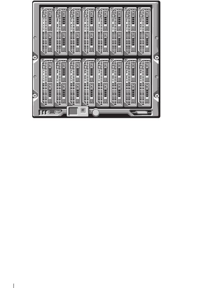
Figure 1-1. Blade Numbering—Half-Height Blades
8 About Your System
12345678
910111213141516
book.book Page 8 Wednesday, March 9, 2011 3:11 PM

Figure 1-2. Blade Numbering—Full Height Blades
Figure 1-3. Blade Numbering—Mixed Full-Height and Half-Height Blades
About Your System 9
12345678
12345678
13 14 15 16
book.book Page 9 Wednesday, March 9, 2011 3:11 PM
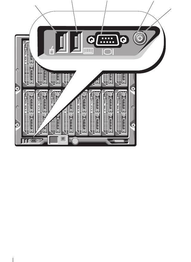
Figure 1-4 shows the control panel features on the M1000e enclosure panel.
Figure 1-4. Control Panel Features
1 USB port (mouse only) 2 USB port (keyboard only)
3 video connector 4 system power button
5 system power indicator
NOTE: The USB and video ports are functional only if an optional iKVM module is
installed.
10 About Your System
2
3
4
1
5
book.book Page 10 Wednesday, March 9, 2011 3:11 PM
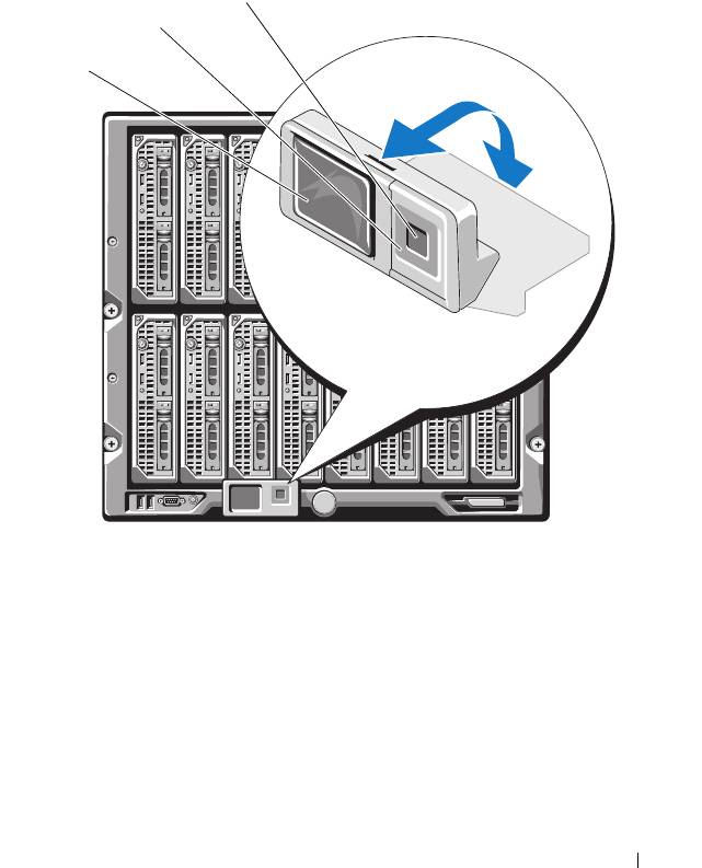
LCD Module
The LCD module provides an initial configuration/deployment wizard, as
well as access to infrastructure and blade information, and error reporting.
See Figure 1-5.
Figure 1-5. LCD Module
1 LCD screen 2 scroll buttons (4)
3 selection ("check") button
About Your System 11
3
2
1
book.book Page 11 Wednesday, March 9, 2011 3:11 PM

book.book Page 12 Wednesday, March 9, 2011 3:11 PM
LCD Module Menus
Table 1-1. LCD Module Screen Navigation Keys
Keys Action
Left and right arrows Use the left and right arrow keys to navigate through the
options in a menu and to scroll text.
Up arrow or down arrow Use the up and down arrow keys to navigate through the
options in a menu, scroll text or
increase a numerical
value
.
Center button Use this button to select a menu option.
Main Menu
The Main Menu options include links to the LCD Setup Menu, Server
Menu, and Enclosure Menu.
LCD Setup Menu
You can change the default language and start-up screen for the LCD menu
screens using this menu.
Server Menu
From the Server Menu dialog box, you can highlight each blade in the
enclosure using the arrow keys, and view its status.
• A blade that is powered off or booting is designated by a gray rectangle. An
active blade is indicated by a green rectangle. If a blade has errors, this
condition is indicated by an amber rectangle.
• To select a blade, highlight it and press the center button. A dialog box
displays the iDRAC IP address of the blade and any errors present.
12 About Your System

book.book Page 13 Wednesday, March 9, 2011 3:11 PM
Enclosure Menu
The Enclosure Menu includes options for Module Status, Enclosure Status,
and Network Summary.
•In the
Module Status
dialog box, you can highlight each component in the
enclosure and view its status.
– A module that is powered off or booting is designated by a gray
rectangle. An active module is indicated by a green rectangle. If a
module has errors, it is indicated by an amber rectangle.
– If a module is selected, a dialog box displays the current status of the
module and any errors present.
•In the
Enclosure Status
dialog box, you can view the enclosure status, any
error conditions, and power consumption statistics.
•The
Network
Summary
screen lists the IP addresses for the CMC, the
iDRAC in each blade, and other components in the enclosure.
About Your System 13

Back-Panel Features
The back panel of the M1000e enclosure supports six I/O modules, one or two
CMC modules, an optional iKVM module, nine fan modules, and six power
supply modules. Figure 1-6 shows a fully configured enclosure.
Figure 1-6. Back Panel Features
1 fan modules (9) 2 primary CMC module
3 I/O modules (6) 4 optional iKVM module
5 secondary CMC module 6 power supplies (6)
14 About Your System
1
2
3
4
5
6
book.book Page 14 Wednesday, March 9, 2011 3:11 PM
Blades
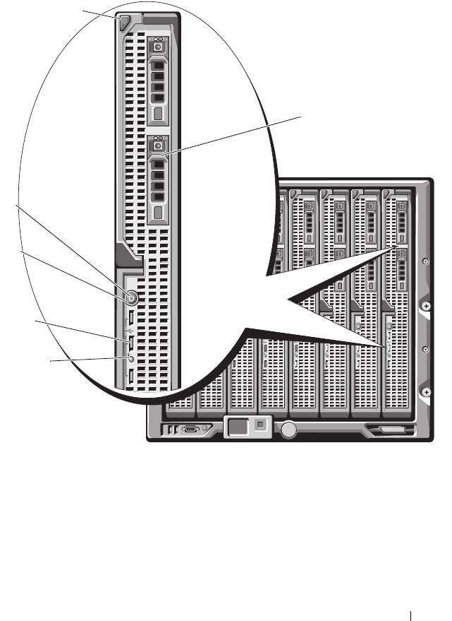
Figure 1-7. Front Panel Features—PowerEdge M910
1 blade-handle release button 2 hard drives (2)
3 blade status/identification indicator 4 USB connectors (3)
5 blade power button 6 blade power indicator
About Your System 15
1
2
6
5
4
3
book.book Page 15 Wednesday, March 9, 2011 3:11 PM

Figure 1-8. Front Panel Features—PowerEdge M905 and M805
1 blade handle release button 2 hard drives (2)
3 blade status/identification indicator 4 USB connectors (3)
5 blade power button 6 blade power indicator
16 About Your System
1
2
6
5
4
3
book.book Page 16 Wednesday, March 9, 2011 3:11 PM
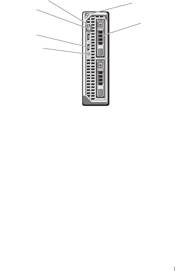
Figure 1-9. Front Panel Features—PowerEdge M710HD
1 blade power indicator 2 blade handle release button
3 hard drives (2) 4 blade status/identification indicator
5 USB connectors (2) 6 blade power button
About Your System 17
1
2
6
3
5
4
book.book Page 17 Wednesday, March 9, 2011 3:11 PM
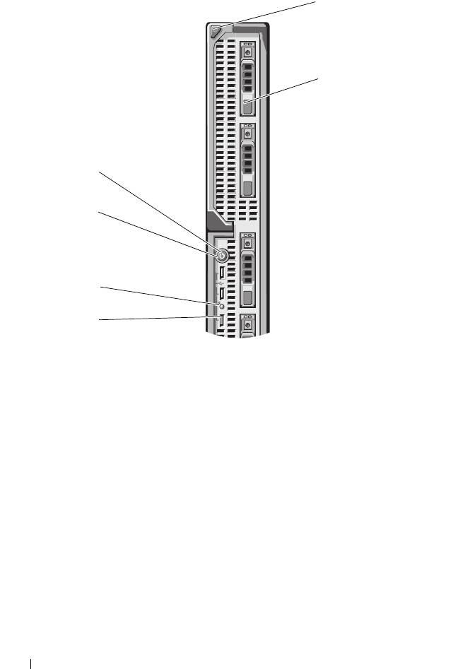
Figure 1-10. Front Panel Features—PowerEdge M710
1 blade handle release button 2 hard drives (4)
3 USB connectors (3) 4 blade status/identification indicator
5 blade power button 6 blade power indicator
18 About Your System
1
2
6
5
4
3
book.book Page 18 Wednesday, March 9, 2011 3:11 PM

Figure 1-11. Front Panel Features—PowerEdge M610x
1 blade handle release button 2 hard drives (2)
3 expansion-card filler-bracket
4 expansion-card slots (2)
retention latch with captive screw
5 blade status/identification indicator 6 USB connectors (2)
7 blade power button 8 blade power indicator
About Your System 19
1
8
7
2
6
5
3
4
book.book Page 19 Wednesday, March 9, 2011 3:11 PM

Figure 1-12. Front Panel Features—PowerEdge M610
1 blade handle release button 2 hard drives (2)
3 blade status/identification indicator 4 USB connectors (2)
5 blade power button 6 blade power indicator
20 About Your System
1
6
5
4
3
2
book.book Page 20 Wednesday, March 9, 2011 3:11 PM
