Dell LATITUDE D400: AC Adapter: Dell™ Latitude™ CS/CS x Portable Computers User's Guide
AC Adapter: Dell™ Latitude™ CS/CS x Portable Computers User's Guide: Dell LATITUDE D400
Оглавление
- Dell™ Latitude™ CS/CS Portable Computers User's Guide
- AC Adapter: Dell™ Latitude™ CS/CS x Portable Computers User's Guide
Back to Contents Page
AC Adapter: Dell™ Latitude™ CS/CS x Portable Computers User's Guide
Using the AC Adapter
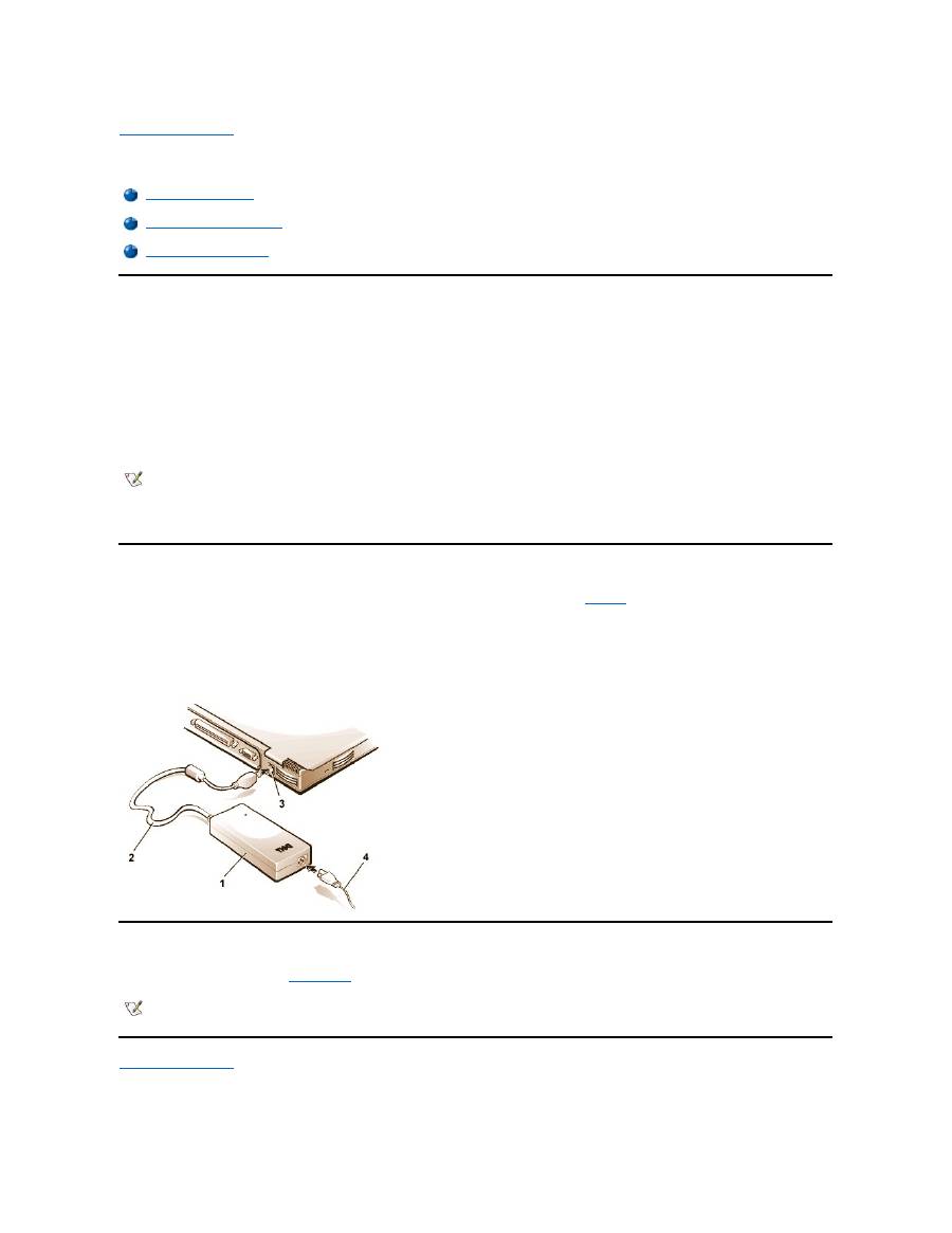
The AC adapter converts AC power to the DC power required by the computer. The AC adapter kit includes the AC adapter with its attached DC
cable (which inputs power to the computer) as well as an AC power cable that connects to an electrical outlet.
You can connect the AC adapter with your computer either turned on or off.
The AC adapter works with electrical outlets worldwide. However, power connectors vary among countries. Before you use AC power in a foreign
country, you may need to obtain a new power cable designed for use in that country.
If the computer is docked to one of Dell's C/Port Family Advanced Port Replicators (APR) or C/Dock Family Expansion Stations, it obtains power
through the APR or expansion station, which must be connected to an electrical outlet.
Connecting the AC Adapter
1.
Connect the AC adapter's attached cable into the computer's AC adapter connector (see
Figure 1
).
2. Plug the AC power cable into the other end of the AC adapter.
3. Plug the AC power cable into an electrical outlet.
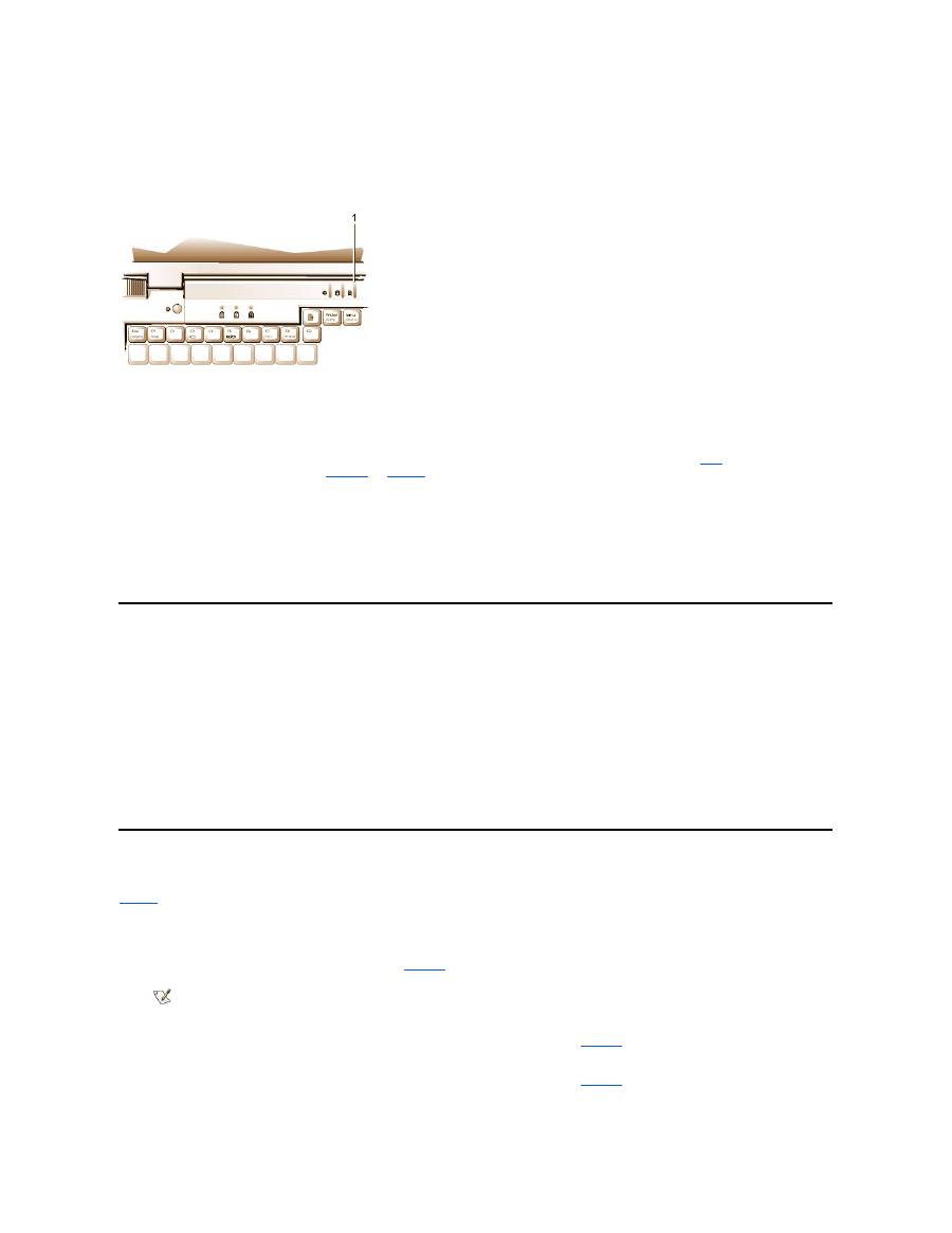
Figure 1. Connecting the AC Adapter
Turning On the Computer
To turn on the computer, press the
power button
.
Back to Contents Page
Using the AC Adapter
Connecting the AC Adapter
Turning On the Computer
NOTE: If you are running your computer on AC power with a battery installed, the AC adapter charges the battery (if needed) and then
maintains the battery's charge.
NOTICE: The AC adapter should be in a ventilated area, such as on a desktop or on the floor, when used to power the computer or
charge the battery. Do not use the AC adapter in a poorly ventilated environment, such as inside a carrying case.
1
AC adapter
2
AC adapter's attached cable
3
AC adapter connector
4
AC power cable
NOTE: If your computer's operating system is "locked up"
—
that is, it does not respond to commands
—
press and hold down the power
button for at least five seconds to turn off the computer.
Back to Contents Page
Power Management Settings: Dell™ Latitude™ CS/CS x Portable Computers User's Guide
Experimenting With Power Conservation
In general, the lower the value you set for each power conservation feature, the longer the battery's charge lasts. On the other hand, setting high
values tends to optimize the computer's performance.
To evaluate the way that different settings affect how long you can operate the computer on battery power versus the relative efficiency of how the
software performs, experiment as follows:
l
Use the computer with all the options set at their default values.
l
Use the computer with all the options disabled or set to
Off
.
l
Use the computer with all the options set to their minimum or maximum values.
Using Key Combinations
Table 1
identifies the power management key combinations.
Table 1. Key Combinations to Activate/Deactivate Features
*
These key combinations do not function with the Advanced Configuration and Power Interface (ACPI
).
Closing the Display
One way to conserve power on the computer is to close the display when the computer is not in use. When you close the display and an external
Experimenting With Power Conservation
Standby Mode
Using Key Combinations
Suspend-to-Disk Mode
Closing the Display
Power Management Properties for Microsoft Windows 98
Suspend Mode
Power Management Properties for Microsoft Windows NT
NOTE: To use key combinations on an external keyboard, enable the
External Hot Key
option in the System Setup program, and
press <Scroll Lock> instead of <Fn>.
Feature
Activate/Deactivate
Turn off display
To activate, press <Fn><d>.*
To deactivate, move the cursor or press a key on the integrated or external keyboard. (If nothing
happens, the computer may be in
suspend
or
standby
mode. Press the power button to resume
normal operation.)
Turn off hard-disk drive
To activate, press <Fn><h>.*
Automatically deactivates when the hard-disk drive is accessed.
NOTE: If a modular hard-disk drive is installed in the C/Dock media bay, you cannot turn off the
hard-disk drive by pressing <Fn><h>
.
Suspend mode
To activate, press <Fn><Esc>.
To deactivate, press the power button.
Suspend-to-disk mode
To activate, press <Fn><a>. (On a French keyboard, press <Fn><q>.)*
To deactivate, press the power button.

monitor is
not
connected, the computer's display shuts off and the computer enters
suspend
mode (
standby
mode in Microsoft
®
Windows
®
98).
To resume work, open the display. (The computer may take several seconds to resume operation.)
Suspend Mode
If your computer is running the Microsoft Windows 95 or Microsoft Windows NT
®
operating system, suspend mode stops almost all computer
activity, but leaves the computer ready to resume operations immediately in about 20 to 30 seconds. Use suspend mode whenever you leave the
computer unattended.
NOTICE: Windows 95 and Windows NT save data to random-access memory (RAM), not to your hard-disk drive, before entering
suspend mode. If the computer enters suspend mode while running on battery power, data loss from RAM can occur if the battery
discharges completely.
Suspend mode conserves battery power by turning off the microprocessor clock; the display; the hard-disk drive; the CD-ROM, DVD-ROM, or LS-
120 drive module (if installed); the external monitor connector; the external keyboard (if attached); the parallel port; the serial port; the touch pad;
and the diskette drive.
You can enter suspend mode immediately by pressing <Fn><Esc> (or <Scroll Lock><Esc> on an external keyboard if the
External Hot Key
option is enabled in the System Setup program).
When you enter suspend mode, the
power indicator
is not lit.
Resume from suspend mode by pressing the power button. The computer may take several seconds to return to normal operation.
Standby Mode
If your computer is running the Microsoft Windows 98 operating system, standby mode turns off the display, stops the hard-disk drive, and turns off
other internal devices so that the computer uses less battery power. When the computer resumes operation from standby mode, the desktop is
restored exactly as it was before entering standby mode.
NOTICE: Windows 98 saves data to random-access memory (RAM), not to your hard-disk drive, before entering standby mode. If the
computer enters standby mode while running on battery power, data loss from RAM can occur if the battery discharges completely.
You can enter standby mode by pressing <Fn><Esc>.
To resume operation from standby mode, press the power button.
Suspend-to-Disk Mode
Suspend-to-disk (S2D) mode copies all system data to a reserved area
—
the S2D partition
—
on the hard-disk drive and then turns off all power to
the computer. When you resume normal operation, the same programs will be running and the same files will be open that were loaded before you
activated this mode.
Place the computer in S2D mode if you intend to store the computer for longer than 40 days. S2D mode preserves the configuration information
stored in nonvolatile random-access memory (NVRAM). The reserve battery maintains this information, but it may run out of energy after 40 days.
If your system is running under
Advanced Power Management
(APM) mode, and if the
External Hot Key
option is enabled in the System Setup
program, you can enter S2D mode by pressing <Fn><a> (or <Scroll Lock><a> on an external keyboard). On a French keyboard, press <Fn><q>
or <Scroll Lock><q>.*
Resume operation from S2D mode by pressing the power button.
If you connect or remove devices while the computer is in S2D mode, the computer automatically recognizes the newly connected devices when it
resumes normal operation.
Some PC Cards may not operate correctly after resuming from S2D mode. If you encounter problems with a card,
remove and reinsert the card
.
NOTE: If an external monitor is connected when you close the display, the computer does not activate suspend mode. You can still use
the external monitor.
NOTES: On resumption from suspend mode, if a password is set, the computer displays the password prompt screen. At the password
prompt screen, if you do not enter a password within 2 minutes, the computer returns to suspend mode.
Suspend mode is known as standby mode under the Microsoft Windows 98 operating system.
NOTE: S2D mode helps preserve system data by quickly saving it to the hard-disk drive if you are about to run out of battery power.
NOTE: Dell creates an appropriately sized S2D partition before shipping the computer to you. Use the S2D utility to remove the file, to
increase the size of the file, or to add the S2D file if you removed it. For more information about altering or creating an S2D file, see the

* These key combinations may not function with future operating systems.
Power Management Properties for Windows 98
Windows 98 with Advanced Power Management (APM) provides the
Power Management
Properties
window for setting power conservation
features.
To access the
Power Management Properties
window and set the power management features, perform the following steps:
1. Click the
Start
button, point to
Settings
, and click
Control Panel
.
2. Double-click the
Power Management Properties
icon.
The
Power Management Properties
window contains the following tabs:
l
Power Scheme
—
allows you to change individual power management settings or select one of three power mode settings
(
Always On
,
Home/Office Desk
, or
Portable/Laptop
) that each provide a set of default power management settings.
l
Alarms
—
allows you to set the
Low Battery
and
Critical Battery
alarms to alert you when the computer battery falls below a
certain percentage. When you received your computer, the
Low Battery
and
Critical Battery
alarm options were not checked.
Dell recommends that you do not select these options.
l
Power Meter
—
allows you to view the percentage of battery life remaining when your computer is operating on battery power. If
your computer is operating on AC power, the computer displays a message.
l
Advanced
—
allows you to display the
Power Meter
on the Windows 98 taskbar and to display a password prompt when the
computer resumes operation from standby mode.
Power Management Properties for Microsoft Windows NT
Dell provides Softex software compatible with the Power Management Controller, which allows you to suspend and resume your portable
computer without affecting your ability to use the docking station or its media bay.
For information about Softex power management software, see the Softex user
’
s guides at
http://www.dell.com/products/notebook/latitude/NT40.htm
and see your
Dell-Installed Microsoft Windows NT Workstation Setup Guide
.
Back to Contents Page
readme.S2D
file, which can be found in the
Dell Utilities
folder on your hard-disk drive or on the S2D diskette that came with your
computer.
Back to Contents Page
Batteries: Dell™ Latitude™ CS/CS x Portable Computers User's Guide
About the Batteries
Your computer includes a standard (34-watt/hour [WH]) or high-capacity (46-WH) lithium ion battery that provides power when an electrical outlet is
not available. The battery is installed on the underside of the computer and forms part of the bottom of the computer. Lithium ion batteries are
longer lived than conventional batteries and do not require replacement as often. Lithium ion batteries do not have the memory effect that is
exhibited by nickel-metal hydride (NiMH) and nickel-cadmium (NiCD) batteries. You do not need to drain a lithium ion battery completely before
recharging it. A lithium ion battery will not forget at which point it is fully charged. NiMH and NiCD batteries may not charge fully if they are partially
drained then recharged.
Do not place spent batteries with common household waste products. Contact local authorities for the location of a chemical waste collection
program nearest you.
Keep the following information in mind when you are running your computer from the battery:
l
From a fully charged standard battery you can expect between 2.5 and 3 hours of battery life; from a fully charged high-capacity battery, you
can expect up to 50 percent greater battery life. Actual performance varies, depending on which power management features are enabled
and which application programs you are using.
l
The
integrated battery charge gauge
lets you check the charge status of an installed or uninstalled battery at any time.
l
The battery
’
s self-test capability alerts you to battery conditions such as low charge.
l
There is no battery memory effect with lithium ion batteries
—
you can charge the battery whenever you like without fear of reducing its
charge capacity.
l
A battery has a life span of up to 350 full charges and 2000 partial charges, provided it is charged at normal room temperature.
Using the Battery
The battery is partially charged when you receive it. Dell recommends that you charge your battery to full capacity before using it to power the
computer.
If you are powering the computer from a battery, try to conserve battery power. A number of factors affect battery operating time:
l
Power conservation features that you use
l
Type of display and microprocessor installed
l
Use of storage media
l
Number and type of PC Cards and other external devices that you use
l
Kinds of application programs that you run
l
Capacity of the memory modules that you install (the higher the capacity, the more power used)
When you activate
suspend
mode (known as
standby
in the Microsoft
®
Windows
®
98 operating system), the computer can remain in suspend
mode on battery power for approximately one week (if the battery was fully charged before activating suspend or standby mode).
If you are going to store the computer, disconnect all devices and turn off the computer. Remove the battery when you store your computer for an
extended period of time. A battery will drain when not in use during prolonged storage. After a long storage period, recharge the battery fully before
About the Batteries
First Low-Battery Warning
Using the Battery
Second Low-Battery Warning
Charging the Battery
Detecting Battery Problems
Charging a Hot Battery
Battery Disposal
Replacing the Battery
About Battery Power
Battery Charge Gauge
Turning On the Computer
NOTE: The battery is designed to work with Dell Latitude CS/CSx portable computers only. Do not use the battery with other computers,
and do not use batteries from other computers with the Dell Latitude CS/CSx.

you attempt to run your computer from battery power.
Charging the Battery
Each time you connect the computer to an electrical outlet or install a battery in a computer that is connected to an electrical outlet, the computer
checks the battery's charge. The AC adapter charges the battery (if needed) and then maintains the battery's charge.
When installed in a computer connected to an electrical outlet, the battery immediately starts charging. The green power indicator remains steady
while the AC adapter charges the battery. The indicator starts blinking when the express charge cycle is complete. While the indicator is blinking,
the AC adapter provides a trickle charge to bring the battery to full capacity. The indicator continues to blink until you remove the battery or
disconnect the computer from its electrical outlet.
NOTICE: If the battery status indicator flashes alternately green and amber while the computer is connected to an electrical outlet,
disconnect the computer from the outlet and allow the computer and the battery to return to room temperature. Then reconnect the
computer to its electrical outlet and continue charging the battery. If the computer is not allowed to return to room temperature, the
battery stops charging before it reaches full capacity.
If the computer is turned off and connected to an electrical outlet through the AC adapter, it takes the AC adapter about 1 hour and 20 minutes to
fully charge a battery that has been completely discharged. If the computer determines that the battery is near full capacity, the AC adapter skips
the express-charging process and starts trickle-charging the battery. If the computer is on, it takes up to 2.5 hours to charge a fully discharged
battery, depending on which devices you are using and which programs you are running.
Charging a Hot Battery
Before you attempt to charge a battery that is hot (either from recent use or from being in a hot environment), note the following information:
l
A hot battery will not charge when you connect the AC adapter to the computer. This safety feature is important because charging a hot
battery shortens the battery
’
s life span and may damage the battery and the computer.
l
If the battery status indicator flashes alternately green and amber, the battery is too hot to start charging. If this occurs, disconnect the
computer from its electrical outlet and allow it and the battery to return to room temperature. Reconnect the computer to the electrical outlet
and continue charging the battery.
l
If the computer is not allowed to return to room temperature, the battery stops charging before it reaches its full capacity.
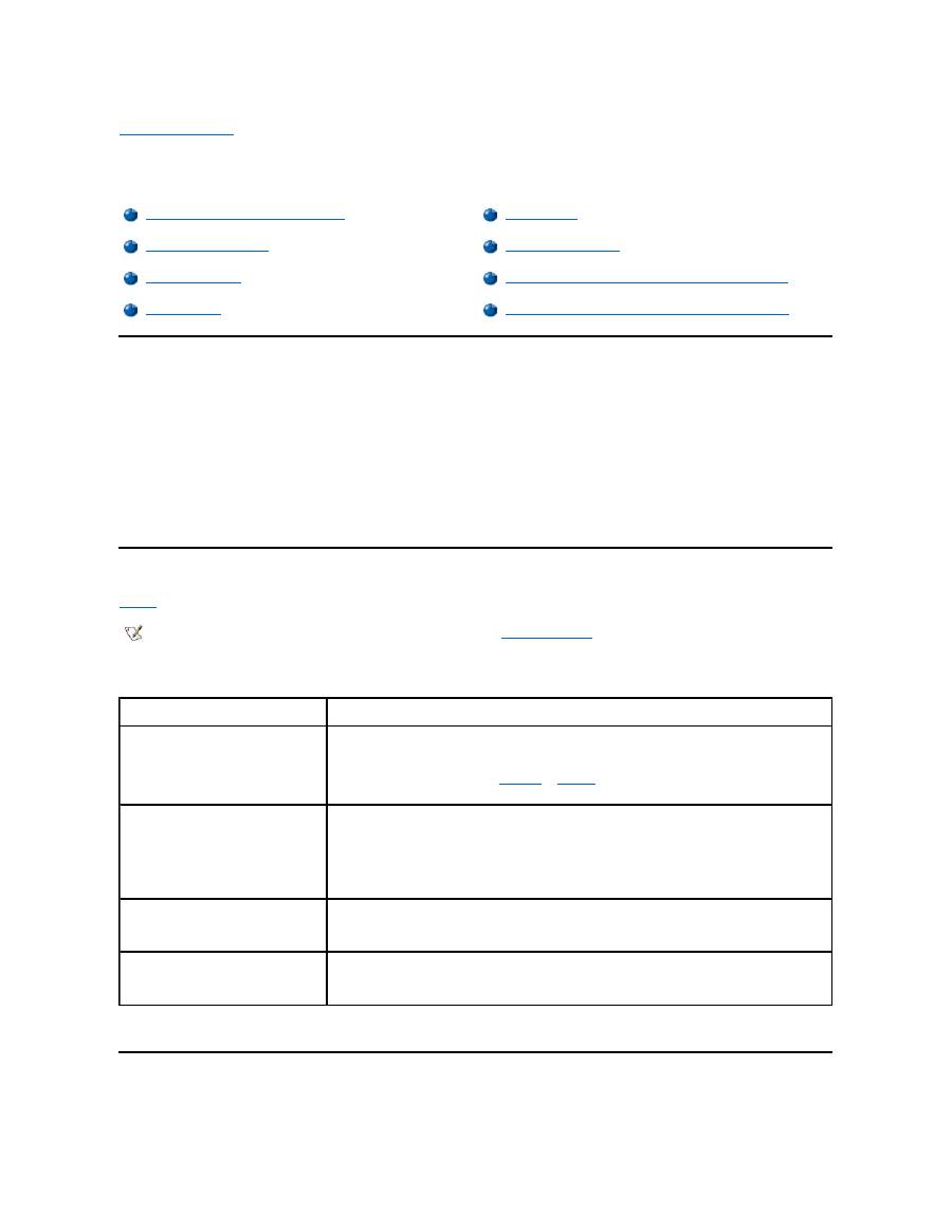
Replacing the Battery
NOTICE: To avoid data loss, do not remove the battery while the computer is turned on unless the computer is connected to an
electrical outlet .
To replace a battery in the battery bay, perform the following steps (see
Figure 1
).
1.
If the computer is docked, undock it following your usual undocking procedure. (See the documentation that came with your docking device.)
2.
If the computer is not docked, preserve your data in one of the following ways and then go to step 3.
l
Connect the computer to an electrical outlet.
l
Place the computer in suspend (or standby) mode by pressing <Fn><Esc> (or <Scroll Lock><Esc> on an external keyboard if
the
External Hot Key
option is enabled in the System Setup program).
l
Place the computer in
S2D mode by pressing <Fn><a> (or <Fn><q> on a French keyboard). When the green power indicator
turns off, continue to step 3.
NOTICE: If you choose to replace the battery with the computer in suspend (or standby) mode, you have up to 4 minutes to complete
the battery replacement.
3.
Remove the battery from the battery bay.
NOTE: For maximum battery performance, charge the battery only at normal room temperature.
NOTE: You can leave the battery in the computer as long as you like. The battery's integrated circuitry prevents the battery from
overcharging.
NOTES: If necessary, print these instructions for reference before proceeding.
You cannot replace the battery while the computer is running on battery power. To replace the battery while the computer is running, you
must connect the computer to an electrical outlet or enter
suspend
(or
standby
) mode or
suspend-to-disk
(S2D) mode.
Close the computer display and turn the computer over. Slide the battery bay latch toward the unlock icon, causing the battery to pop up
slightly on one side (see
Figure 1
). Continue to hold the latch in the unlock position with one hand while pivoting the battery up and out of the
bay with the other hand. Release the latch.
Figure 1. Removing a Battery
4.
Position the new battery so that its three alignment tabs fit into the three slots in the outside wall of the computer, and lower the battery into its
compartment. Make sure that the battery snaps into place, flush with the surrounding surface, and make sure that the battery latch is
completely closed before turning the computer over.
5.
If you put the computer into suspend mode or S2D mode in step 2, press the power button to resume normal operation.
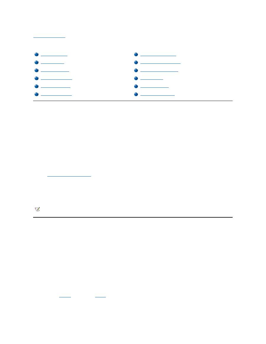
Battery Charge Gauge
The battery charge gauge, located on the battery and accessible on the underside of the computer, consists of five indicators and a test button.
Each indicator represents 20 percent of full charge. If only one indicator lights up, recharge the battery before using it.
To check the charge level, press the battery test button (see
Figure 2
). The appropriate number of indicators lights up for a few seconds to indicate
the amount of charge remaining in the battery. For example, if three indicators light up, your battery has between 40 percent and 60 percent of its
charge left.
Figure 2. Battery Charge Gauge
Percentage of Charge
The
battery charge gauge
uses its five indicator lights to show the percent of charge remaining in the battery:
l
If one indicator lights up, the battery has 1 to 20 percent of its charge remaining.
l
If two indicators light up, the battery has 21 to 40 percent of its charge remaining.
l
If three indicators light up, the battery has 41 to 60 percent of its charge remaining.
l
If four indicators light up, the battery has 61 to 80 percent of its charge remaining.
l
If five indicators light up, the battery has 81 to 100 percent of its charge remaining.
NOTES: An indicator that blinks rapidly indicates a temporary failure or a potentially recoverable failure like overheating. Allow the
battery to cool for several minutes before checking the charge level again.
If the battery has permanently failed or completely discharged, no charge gauge indicators will light when you press the battery test
button. If you install a failed or completely discharged battery in the computer and the
battery status indicator
flashes amber rapidly, the
battery has failed. If the battery status indicator turns solid green, allow the battery to charge overnight and check it the next day. If the
battery is fully discharged, it takes a much longer time than usual to recharge it.
To purchase a new battery,
call Dell
or access the Dell World Wide Web site at
http://www.dell.com
.
Dispose
of the old battery
properly.
First Low-Battery Warning
The first low-battery warning
—
a blinking amber battery status indicator
—
occurs when you have about 15 minutes of battery life left under current
conditions and the computer is not connected to an electrical outlet.
Figure 3. Battery Status Indicator
NOTICE: When you see a low-battery warning, save your work immediately. Then replace the battery or connect your computer to an
electrical outlet.
Normally, if no input/output (I/O) activity occurs within 75 seconds after the first low-
battery warning, the computer enters
S2D
mode. If the computer
has no S2D partition, the computer enters
suspend
(or
standby
) mode, where it can preserve data for several hours.
Alternatively, you may have set the computer to enter S2D mode after a certain amount of time with no I/O activity. In this case the computer enters
S2D mode before flashing the final low-battery warning.
Once S2D mode is activated, no further power is consumed.
NOTICE: Never turn off the computer while the drive access indicator is on. Doing so could cause data loss. Instead, close all of your
application programs before you turn off the computer.
Second Low-Battery Warning
The second low-battery warning
—
a steady amber battery status indicator
—
occurs when you have about 5 minutes of battery life left under current
conditions and the computer is not connected to an electrical outlet.
After the second low-battery warning, if no further I/O activity occurs within 15 seconds, the computer enters S2D mode. If the computer has no
S2D partition, it enters suspend mode, in which it can preserve data for several hours.
If the computer is already in suspend mode when a final low-battery warning occurs, the computer enters S2D mode immediately. If S2D mode has
been disabled, the computer reenters suspend mode.
NOTICE: To avoid losing data (and possibly corrupting data areas on your hard-disk drive), save your work immediately after a
second low-battery warning. Then connect your computer to an electrical outlet, or place the computer in suspend mode. If the
battery runs completely out of power, the computer shuts off without properly closing any open files.
Detecting Battery Problems
A battery problem may prevent the battery from being charged to its full potential and can lead to unpredictable operation. To obtain a new battery,
call Dell
or access the Dell World Wide Web site at
http://www.dell.com
.
Dell suggests you follow these precautions when using the battery:
l
To avoid installing a defective battery in your computer, first check the battery's charge, indicated by the battery charge indicators on the
battery itself, by pressing the battery test button (see
Figure 2
).
l
If, after you insert the battery in the computer, the computer's battery status indicator (see
Figure 3
) flashes alternately green and amber, the
battery is too hot to charge. Turn off the computer, and let the battery and computer cool to room temperature.
l
If, after you insert the battery in the computer, the computer's battery status indicator (see
Figure 3
) flashes amber for 4 seconds when you
connect or disconnect the AC adapter or when you press the power button, you need to replace the battery.
1
Battery status indicator
NOTE: If the battery has 0 (zero) percent charge, you cannot use the battery test button to check the battery's capacity. The
battery gauge indicators will not light if the battery is completely drained.

l
If, after you insert the battery in the computer, the computer's battery status indicator (see
Figure 3
) flashes rapidly amber, the battery is
defective and needs to be replaced.
Battery Disposal
When your battery no longer holds a charge, call your local waste disposal agency or environmental agency for advice on disposing the computer
’
s
lithium ion battery.
About Battery Power
You automatically conserve battery power each time you connect the computer to an electrical outlet. The battery is even being recharged when
you use AC power. The battery's life expectancy is largely determined by the number of charges it receives, so use an electrical outlet to run the
computer whenever possible.
You can customize power management by individually controlling the computer's
power conservation features
. These features reduce power
consumption by monitoring application programs and computer devices for inactivity and slowing down or stopping some of the computer
’
s
internal devices.
Experiment with power conservation features to achieve the optimum power conservation for your work environment.
Turning On the Computer
To turn on the computer, press the
power button
.
Back to Contents Page
CAUTION: Do not puncture or incinerate the battery.
NOTE
:
This computer is supplied with a lithium ion battery. Lithium ion batteries are longer lived than conventional batteries and do not
require replacement as often. Do not place spent batteries in common household waste products. Contact local authorities for the
location of a chemical waste collection program nearest you. To purchase a new battery,
call Dell
or access the Dell World Wide Web
site at
http://www.dell.com
.
NOTES: When you use power conservation features, you often trade some of the performance of the computer for increased battery
operating time. For example, if you turn off the hard-disk drive, you may experience a delay the next time the computer tries to access
the hard-disk drive.
Other power conservation features, such as
suspend
(or
standby
) mode, stop almost all system activity. They allow you to maximize
power conservation when your work is interrupted.
NOTE: If your computer's operating system is "locked up"
—
that is, it does not respond to commands
—
press and hold down the power
button for at least five seconds to turn off the computer.

Back to Contents Page
CD-ROM and DVD- ROM Drives: Dell™ Latitude™ CS/CS x Portable Computers User's Guide
Using CD-ROM and DVD-ROM Drives
CD-ROM and DVD-ROM drives are read-only devices that can play most commercially available 8- or 12-centimeter (cm) sound and video CDs.
Dell installed the appropriate CD-ROM device drivers on your hard-
disk drive. Dell also installed the drivers that will allow a DVD
-ROM drive to
play most CDs and read data from a DVD.
To use a CD-ROM or DVD-ROM drive, install it in the computer
’
s
external media bay
.
NOTICE:
Protect the CD-ROM and DVD-ROM drives when they are not in the external media bay. Do not squeeze a drive or place
objects on top of it; doing so could damage the drive motor. Keep the drive as clean as possible.
To play a CD or DVD, press the eject button on the face of the CD-ROM or DVD-ROM drive or press <Fn><F10>. When the tray slides out, place
the disc into the tray, label side up. Make sure that the CD or DVD is seated correctly on the spindle by pressing down on the disc until it clicks in
place. Then gently push in the tray.
NOTICE:
If the CD or DVD is not seated correctly, the disc or drive can be damaged.
NOTICE:
Do not use the CD-ROM or DVD-ROM drive while the computer is in motion. Doing so could interrupt the flow of data
between the CD-ROM or DVD-ROM drive and the hard-disk or diskette drive.
When the CD-ROM or DVD-ROM drive is in use, the
drive access indicator
blinks.
If you are using the Microsoft Windows 95 or Windows 98 operating system, disable the autoplay feature while you use the CD-ROM or DVD-ROM
drive. (The autoplay feature can interfere with the computer
’
s
power management
functions.) If Dell installed the operating system, the autoplay
feature has been disabled. If you reinstall the operating system or if you installed it yourself, be sure to disable the autoplay feature if you want to
use the CD-ROM or DVD-ROM drive.
For instructions on changing the
Auto Insert Notification
option, see the operating system user
’
s guide.
Caring for CDs and DVDs
When handling and using CDs and DVDs, follow these precautions:
l
Never use a damaged or warped CD or DVD.
l
Always hold the CD or DVD by its edges. Do not touch the surface of the disc.
l
Use a clean, dry cloth to remove dust, smudges, or fingerprints from the surface of the CD or DVD. When cleaning, wipe from the center of
the CD or DVD to the edge.
l
Never use solvents, such as benzene, record cleaners, or antistatic sprays, to clean the CD or DVD.
l
Do not write on the surface of the CD or DVD.
l
Store CD or DVDs in their containers, placing them in a cool, dry place. Extreme temperatures may damage CDs or DVDs.
l
Do not bend or drop a CD or DVD.
l
Do not place objects on top of a CD or DVD.
Types of Supported Discs
Using CD-ROM and DVD-ROM Drives
Caring for CDs and DVDs
Types of Supported Discs
NOTE: "Reading data" does not refer to playing a movie. However, if you are using the Microsoft
®
Windows
®
95 or Windows 98
operating system, you can play DVD movies in your DVD-ROM drive by installing a zoomed video (ZV) PC Card, such as a hardware
Moving Picture Experts Group (MPEG) decoder, in the upper PC card slot. You must also install the drivers that came with the card.

Your computer's CD-ROM and DVD-ROM drives are able to play the following disc formats:
l
CD-ROM red-book audio discs (CD-DA)
l
CD-ROM yellow-book mode-1 and mode-2 data discs
l
CD-ROM XA (mode-2 form 1 and form 2; without Adaptive Differential Pulse Code modulation [ADPCM])
l
CD-I (mode-2 form 1 and form 2)
l
CD-I Ready
l
CD-Bridge
l
Photo CD, CD-recordable (CD-R) (single and multisession)
l
Video CD
l
CD-rewritable (CD-RW). The 24x CD-ROM and DVD-ROM drives support reading CD-RW discs. This format is supported as read-only;
neither the CD-ROM nor the DVD-ROM drive can write to CD-RW discs.
l
DVD-5 (the DVD-ROM drive supports the DVD-5 format)
Back to Contents Page
Back to Contents Page
Contacting Dell: Dell™ Latitude™ CS/CS x Portable Computers User's Guide
Overview
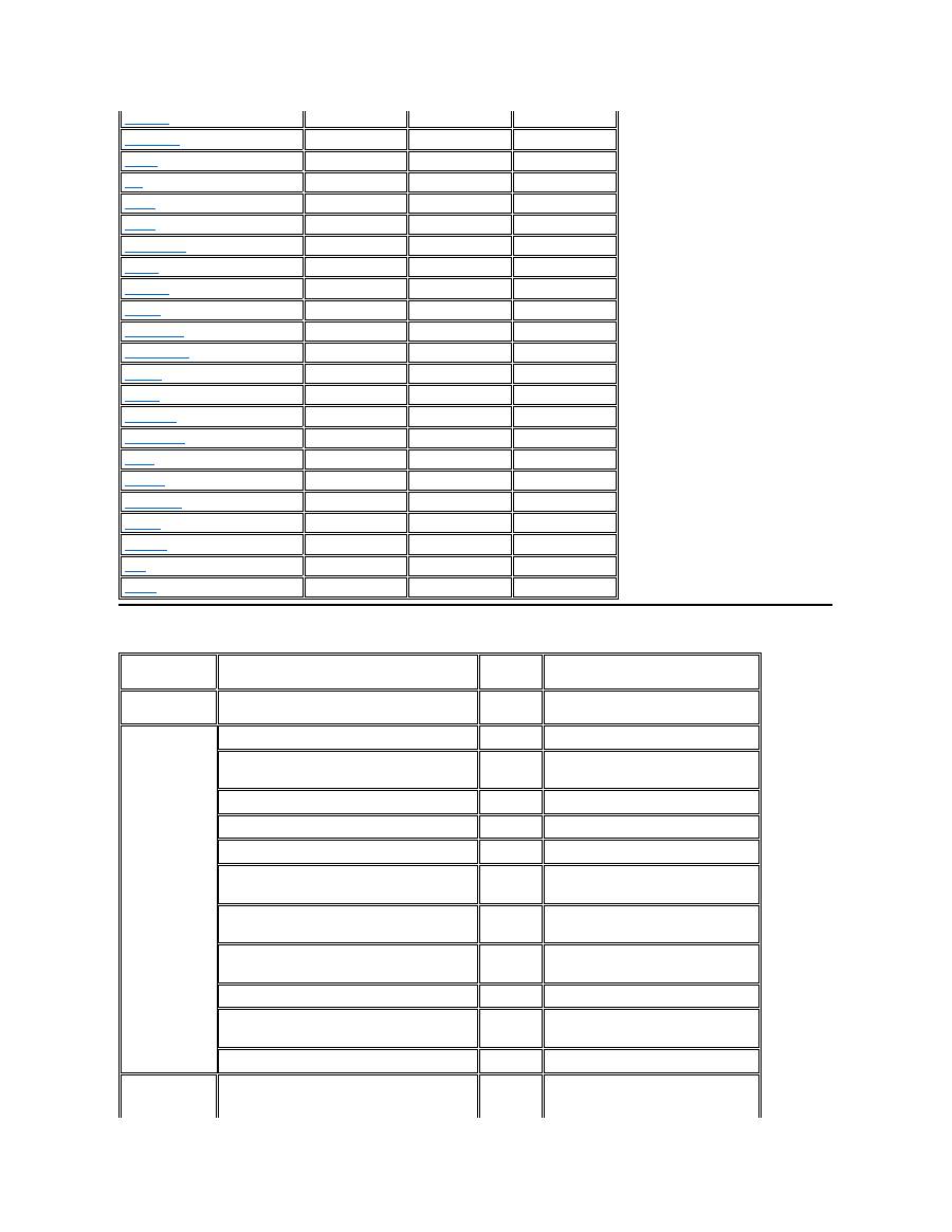
When you need to contact Dell, use the telephone numbers, codes, and electronic addresses provided in the following sections. "
International
Dialing Codes
" provides the various codes required to make long-distance and international calls. "
Americas Contact Numbers
," "
Europe Contact
Numbers
," and "
Asia and Other Regions Contact Numbers
" provide local telephone numbers, area codes, toll-free numbers, and E-mail
addresses, if applicable, for each department or service available in various countries around the world.
If you are making a direct-dialed call to a location outside of your local telephone service area, determine which codes to use (if any) in
"
International Dialing Codes
," in addition to the local numbers provided in the other sections.
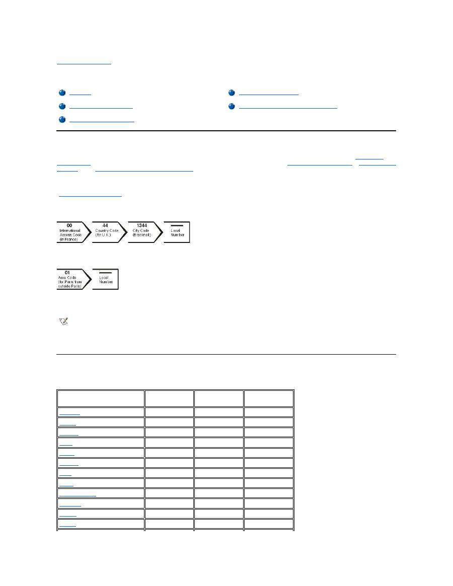
For example, to place an international call from Paris, France to Bracknell, England, dial the international access code for France followed by the
country code for the U.K., the city code for Bracknell, and then the local number as shown in the following illustration:
To place a long-distance call within your own country, use area codes instead of international access codes, country codes, and city codes. For
example, to call Paris, France from Montpellier, France, dial the area code plus the local number as shown in the following illustration:
The codes required depend on where you are calling from as well as the destination of your call; in addition, each country has a different dialing
protocol. If you need assistance in determining which codes to use, contact a local or an international operator.
International Dialing Codes
Click a listed country to obtain the appropriate contact numbers.
Overview
Europe Contact Numbers
International Dialing Codes
Asia and Other Regions Contact Numbers
Americas Contact Numbers
NOTES: Toll-free numbers are for use only within the country for which they are listed. Area codes are most often used to call long
distance within your own country (not internationally)
—
in other words, when your call originates in the same country you are calling.
Have your Express Service Code ready when you call. The code helps Dell's automated-support telephone system direct your call
more efficiently.
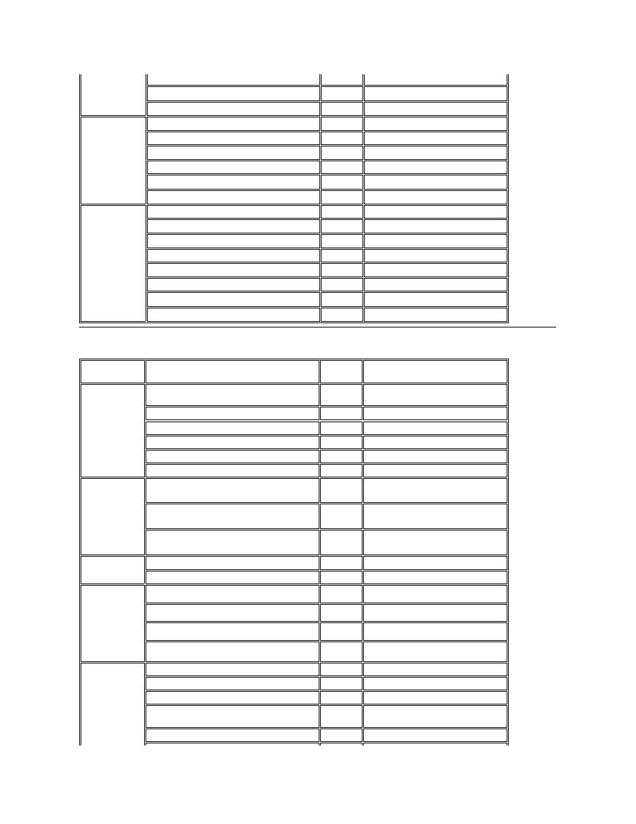
Country (City)
International
Access Code
Country Code
City Code
Australia
(Sydney)
0011
61
2
Austria
(Vienna)
900
43
1
Belgium
(Brussels)
00
32
2
Brazil
0021
55
51
Brunei
—
673
—
Canada
(North York, Ontario)
011
—
Not required
Chile
(Santiago)
—
56
2
China
(Xiamen)
—
86
592
Czech Republic
(Prague)
00
420
2
Denmark
(Horsholm)
009
45
Not required
Finland
(Helsinki)
990
358
9
France
(Paris) (Montpellier)
00
33
(1) (4)
Americas Contact Numbers
Germany
(Langen)
00
49
6103
Hong Kong
001
852
Not required
Ireland
(Bray)
16
353
1
Italy
(Milan)
00
39
2
Japan
(Kawasaki)
001
81
44
Korea
(Seoul)
001
82
2
Luxembourg
00
352
—
Macau
—
853
Not required
Malaysia
(Penang)
00
60
4
Mexico
(Colonia Granada)
95
52
5
Netherlands
(Amsterdam)
00
31
20
New Zealand
00
64
—
Norway
(Lysaker)
095
47
Not required
Poland
(Warsaw)
011
48
22
Singapore
(Singapore)
005
65
Not required
South Africa
(Johannesburg)
09/091
27
11
Spain
(Madrid)
07
34
91
Sweden
(Upplands Vasby)
009
46
8
Switzerland
(Geneva)
00
41
22
Taiwan
002
886
—
Thailand
001
66
—
U.K.
(Bracknell)
010
44
1344
U.S.A.
(Austin, Texas)
011
1
Not required
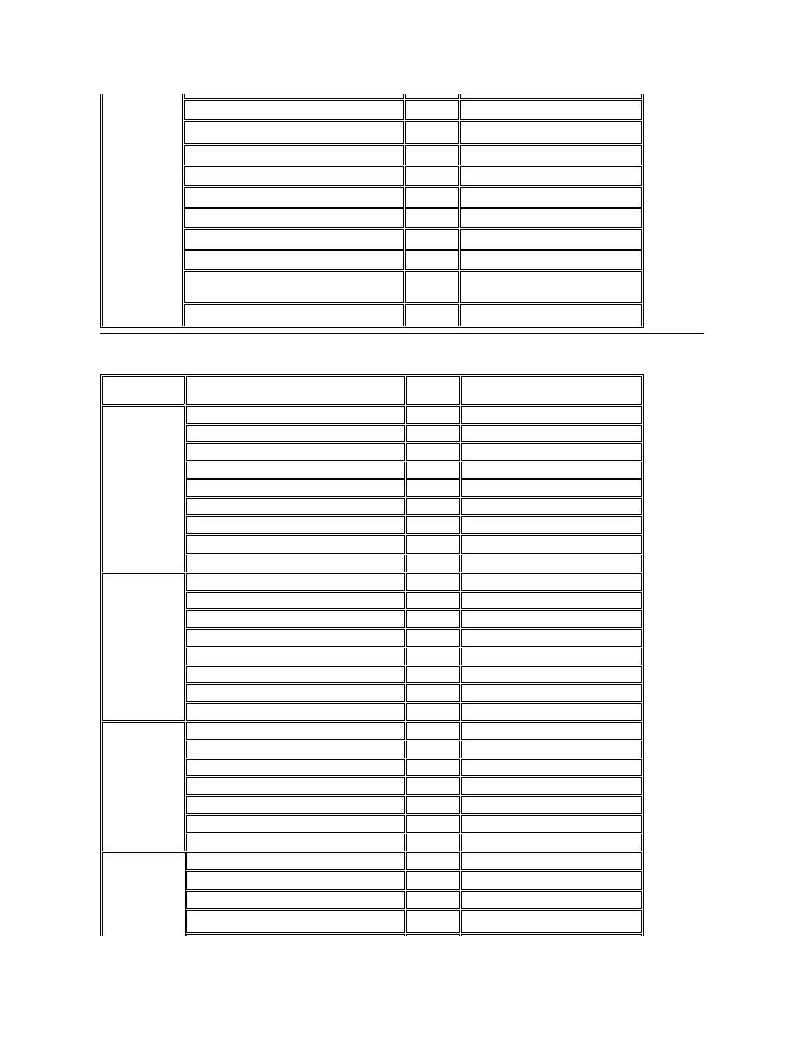
Country (City)
Department Name or Service
Area
Code
Local Number or
Toll-Free Number
Brazil
Sales, Customer Support, Technical Support
toll free: 0800 90 3355
Canada
(North York,
Ontario)
NOTE:
Customers in
Canada call the
U.S.A. for access
to TechConnect
BBS.
Automated Order-Status System
toll free: 1-800-433-9014
AutoTech (Automated technical support)
toll free: 1-800-247-9362
Customer Care (From outside Toronto)
toll free: 1-800-387-5759
Customer Care (From within Toronto)
416
758-2400
Customer Technical Support
toll free: 1-800-847-4096
Sales (Direct Sales
—
from outside Toronto)
toll free: 1-800-387-5752
Sales (Direct Sales
—
from within Toronto)
416
758-2200
Sales (Federal government, education, and
medical)
toll free: 1-800-567-7542
Sales (Major Accounts)
toll free: 1-800-387-5755
TechConnect BBS (Austin, Texas, U.S.A.)
512
728-8528
TechFax
toll free: 1-800-950-1329
Chile
(Santiago)
Sales, Customer Support, and Technical Support
toll free: 1230-020-4823

NOTE:
Customers in
Chile call the
U.S.A. for sales,
customer, and
technical
assistance
Latin America
NOTE:
Customers in
Latin America
call the U.S.A. for
sales, customer,
and technical
assistance.
Customer Technical Support (Austin, Texas,
U.S.A.)
512
728-4093
Customer Service (Austin, Texas, U.S.A.)
512
728-3619
Fax (Technical Support and Customer Service)
(Austin, Texas, U.S.A.)
512
728-3883
Sales (Austin, Texas, U.S.A.)
512
728-4397
SalesFax (Austin, Texas, U.S.A.)
512
728-4600
728-3772
Mexico
(Colonia
Granada)
NOTE:
Customers in
Mexico call the
U.S.A. for access
to the Automated
Order-Status
System and
AutoTech.
Automated Order-Status System (Austin, Texas,
U.S.A.)
512
728-0685
AutoTech (Automated technical support) (Austin,
Texas, U.S.A.)
512
728-0686
Customer Technical Support
525
228-7870
Sales
525
228-7811
toll free: 91-800-900-37
toll free: 91-800-904-49
Customer Service
525
228-7878
Main
525
228-7800
U.S.A.
(Austin, Texas)
Automated Order-Status System
toll free: 1-800-433-9014
AutoTech (Automated technical support)
toll free: 1-800-247-9362
Dell Home and Small Business Group:
Customer Technical Support (Return Material
Authorization Numbers)
toll free: 1-800-624-9896
Customer Service
(Credit Return Authorization Numbers)
toll free: 1-800-624-9897
National Accounts
(systems purchased by established Dell national accounts [have your account number
handy], medical institutions, or value-added resellers [VARs]):
Customer Service and Technical Support (Return
Material Authorization Numbers)
toll free: 1-800-822-8965
Public Americas International
(systems purchased by governmental agencies [local, state, or federal] or
educational institutions):
Customer Service and Technical Support (Return
Material Authorization Numbers)
toll free: 1-800-234-1490
Dell Sales
toll free: 1-800-289-3355
toll free: 1-800-879-3355
Europe Contact Numbers
Spare Parts Sales
toll free: 1-800-357-3355
DellWare
™
toll free: 1-800-753-7201
DellWare FaxBack Service
512
728-1681
Fee-Based Technical Support
toll free: 1-800-433-9005
Sales (Catalogs)
toll free: 1-800-426-5150
Fax
toll free: 1-800-727-8320
TechFax
toll free: 1-800-950-1329
TechConnect BBS
512
728-8528
Dell Services for the Deaf, Hard-of-Hearing, or
Speech-Impaired
toll free: 1-877-DELLTTY
(1-877-335-5889)
Switchboard
512
338-4400
Country (City)
Department Name or Service
Area
Code
Local Number or
Toll-Free Number
Austria
(Vienna)
NOTE:
Customers in
Austria call
Langen,
Germany for
Technical
Support and
Customer Care.
Switchboard
01
491 040
Home/Small Business Sales
01
795676-02
Home/Small Business Sales Fax
01
795676-05
Home/Small Business Customer Care
01
795676-03
Preferred Accounts/Corporate Customer Care
0660-8056
Home/Small Business Technical Support
01
795676-04
Preferred Accounts/Corporate Technical Support
0660-8779
Web site:
support.euro.dell.com/at
E-mail: tech_support_germany@dell.com
Belgium
(Brussels)
Technical Support
02
481 92 88
Customer Care
02
481 91 19
Home/Small Business Sales
toll free: 0800 16884
Corporate Sales
02
481 91 00
Fax
02
481 92 99
Switchboard
02
481 91 00
Web site:
support.euro.dell.com/be
E-mail: tech_be@dell.com
Czech Republic
(Prague)
Technical Support
02
22 83 27 27
Customer Care
02
22 83 27 11
Fax
02
22 83 27 14
TechFax
02
22 83 27 28
Switchboard
02
22 83 27 11
Web site:
support.euro.dell.com/cz
E-mail: czech_dell@dell.com
Denmark
(Horsholm)
NOTE:
Customers in
Denmark call
Sweden for fax
Technical Support
45170182
Customer Care
45170181
Switchboard
45170100
Fax Technical Support (Upplands Vasby, Sweden)
859005594

technical support.
Fax Switchboard
45170117
Web site:
support.euro.dell.com/dk
E-mail: den_support@dell.com
Finland
(Helsinki)
Technical Support
09
253 313 60
Technical Support Fax
09
253 313 81
Customer Care
09
253 313 61
Fax
09
253 313 99
Switchboard
09
253 313 00
Web site:
support.euro.dell.com/fi
E-mail: fin_support@dell.com
France
(Paris/Montpellier)
Technical Support
0803
387 270
Customer Care (Paris)
01
47 62 68 92
Customer Care (Montpellier)
04
67 06 61 96
TechConnect BBS (Montpellier)
04
67 22 53 04
Fax (Montpellier)
04
67 06 60 07
Switchboard (Paris)
01
47 62 69 00
Switchboard (Montpellier)
04
67 06 60 00
Web site:
support.euro.dell.com/fr
E-mail: web_fr_tech@dell.com
Germany
(Langen)
Technical Support
06103
971-200
Technical Support Fax
06103
971-222
Home/Small Business Customer Care
06103
971-530
Corporate Customer Care
06103
971-560
Preferred Accounts Customer Care
06103
971-420
TechConnect BBS
06103
971-666
Switchboard
06103
971-0
Web site:
http://www.dell.de/support
E-mail: tech_support_germany@dell.com
Ireland
(Bray)
NOTE:
Customers in
Ireland call the
U.K. for
Home/Small
Business
customer
assistance.
Technical Support
1-850-543-543
Customer Care
01
204 4026
Home/Small Business Customer Care (Bracknell,
U.K.)
0870 906 0010
Sales
1-850-235-235
SalesFax
01
286 2020
Fax
01
286 6848
TechConnect BBS
01
204 4711
TechFax
01
204 4708
Switchboard
01
286 0500
Web site:
support.euro.dell.com/ie
E-mail: dell_direct_support@dell.com
Italy
(Milan)
Technical Support
2
57782.690
Customer Care
2
57782.555
Sales
2
57782.411
Fax
2
57503530
Switchboard
2
57782.1

Web site:
support.euro.dell.com/it
E-mail: support_italy@dell.com
Luxembourg
NOTE:
Customers in
Luxembourg call
Belgium for
sales, customer,
and technical
assistance.
Technical Support (Brussels, Belgium)
02
481 92 88
Home/Small Business Sales (Brussels, Belgium)
toll free: 080016884
Corporate Sales (Brussels, Belgium)
02
481 91 00
Customer Care (Brussels, Belgium)
02
481 91 19
Switchboard (Brussels, Belgium)
02
481 91 00
Fax (Brussels, Belgium)
02
481 92 99
Web site:
support.euro.dell.com/be
E-mail: tech_be@dell.com
Netherlands
(Amsterdam)
Technical Support
020
581 8838
Customer Care
020
581 8740
Home/Small Business Sales
toll free: 0800-0663
Home/Small Business SalesFax
020
682 7171
Corporate Sales
020
581 8818
Corporate SalesFax
020
686 8003
Fax
020
686 8003
Switchboard
020
581 8818
Web site:
support.euro.dell.com/nl
Norway
(Lysaker)
NOTE:
Customers in
Norway call
Sweden for fax
technical support.
Technical Support
671 16882
Customer Care
671 16881
Switchboard
671 16800
Fax Technical Support (Upplands Vasby, Sweden)
590 05 594
Fax Switchboard
671 16865
Web site:
support.euro.dell.com/no
E-mail: nor_support@dell.com
Poland
(Warsaw)
Technical Support
22
60 61 999
Customer Care
22
60 61 999
Sales
22
60 61 999
Switchboard
22
60 61 999
Fax
22
60 61 998
Web site:
support.euro.dell.com/pl
E-mail: pl_support@dell.com
Spain
(Madrid)
Technical Support
902 100 130
Corporate Customer Care
902 118 546
Home/Small Business Customer Care
902 118 540
TechConnect BBS
91
329 33 53
Corporate Sales
902 100 185
Home/Small Business Sales
902 118 541
Switchboard
91
722 92 00
Web site:
support.euro.dell.com/es
E-mail: es_support@dell.com
Sweden
(Upplands Vasby)
Technical Support
08
590 05 199
Customer Care
08
590 05 169
Fax Technical Support
08
590 05 594
Asia and Other Regions Contact Numbers
Sales
08
590 05 185
Web site:
support.euro.dell.com/se
E-mail: swe_support@dell.com
Switzerland
(Geneva)
Technical Support
0844 811 411
Customer Care
0848 802 802
Switchboard
022
799 01 01
Fax
022
799 01 90
Web site:
support.euro.dell.com/ch
E-mail: swisstech@dell.com
U.K.
(Bracknell)
Technical Support
0870-908-0800
Corporate Customer Care
01344
720206
Home/Small Business Customer Care
0870-906-0010
TechConnect BBS
0870-908-0610
Sales
01344
720000
AutoFax
0870-908-0510
Web site:
support.euro.dell.com/uk
E-mail: dell_direct_support@dell.com
Country (City)
Department Name or Service
Area
Code
Local Number or
Toll-Free Number
Australia
(Sydney)
Customer Technical Support (Dell™ Dimension™
systems only)
1-300-65-55-33
Customer Technical Support (Other systems)
toll free: 1-800-633-559
Customer Care
toll free: 1-800-819-339
Corporate Sales
toll free: 1-800-808-385
Transaction Sales
toll free: 1-800-808-312
Fax
toll free: 1-800-818-341
Brunei
NOTE:
Customers in
Brunei call
Malaysia for
customer
assistance.
Customer Technical Support
(Penang, Malaysia)
810 4966
Customer Service
(Penang, Malaysia)
810 4949
Transaction Sales
(Penang, Malaysia)
810 4955
China
(Xiamen)
Customer Service
toll free: 800 858 2437
Sales
toll free: 800 858 2222
Hong Kong
NOTE:
Customers in
Hong Kong call
Malaysia for
customer
assistance.
Technical Support
toll free: 800 96 4107
Customer Service (Penang, Malaysia)
810 4949
Transaction Sales
toll free: 800 96 4109
Corporate Sales
toll free: 800 96 4108
Japan
(Kawasaki)
Technical Support
toll free: 0088-22-7890
Technical Support (Server)
toll free: 0120-1984-35
Technical Support (Dimension and Inspiron™)
toll free: 0120-1982-56
Technical Support (WorkStation, OptiPlex™, and
Latitude™
)
toll free: 0120-1984-39
Y2K Support
044
556-4298

Customer Care
044
556-4240
Direct Sales
044
556-3344
Commercial Sales
044
556-3430
556-3440
Faxbox Service
03-5972-5840
Switchboard
044
556-4300
Korea
(Seoul)
NOTE:
Customers in
Korea call
Malaysia for
customer
assistance.
Technical Support
toll free: 080-200-3800
Transaction Sales
toll free: 080-200-3600
Corporate Sales
toll free: 080-200-3900
Customer Service (Penang, Malaysia)
810 4949
Fax
394 3122
Switchboard
287 5600
Macau
NOTE:
Customers in
Macau call
Malaysia for
customer
assistance.
Technical Support
toll free: 0800 582
Customer Service (Penang, Malaysia)
810 4949
Transaction Sales
toll free: 0800 581
Malaysia
(Penang)
Technical Support
toll free: 1 800 888 298
Customer Service
04
810 4949
Transaction Sales
toll free: 1 800 888 202
Corporate Sales
toll free: 1 800 888 213
New Zealand
Technical Support
(Dell Dimension systems only)
($2.50 + GST per call)
0900 51010
Technical Support (Other systems)
0800 446 255
Customer Service
0800 444 617
Sales
0800 441 567
Fax
0800 441 566
Singapore
(Singapore)
NOTE:
Customers in
Singapore call
Malaysia for
customer
assistance.
Technical Support
toll free: 800 6011 051
Customer Service (Penang, Malaysia)
04
810 4949
Transaction Sales
toll free: 800 6011 054
Corporate Sales
toll free: 800 6011 053
South Africa
(Johannesburg)
Technical Support
011
709 7710
Customer Care
011
709 7710
Sales
011
706 7700
Fax
011
709 0495
Switchboard
011
709 7700
Web site:
support.euro.dell.com/za
E-mail: dell_za_support@dell.com
Southeast
Asian/Pacific
Countries
(excluding
Australia, Brunei,
China, Hong
Kong, Japan,
Korea, Macau,
Malaysia, New
Zealand,
Singapore,
Customer Technical Support, Customer Service,
and Sales (Penang, Malaysia)
60 4 810-4810

Back to Contents Page
Taiwan, and
Thailand
—
refer to
individual listings
for these
countries)
Taiwan
NOTE:
Customers in
Taiwan call
Malaysia for
customer
assistance.
Technical Support
toll free:
0080 651 226/0800 33 557
Customer Service (Penang, Malaysia)
810 4949
Transaction Sales
toll free:
0080 651 228/0800 33 556
Corporate Sales
toll free:
0080 651 227/0800 33 555
Thailand
NOTE:
Customers in
Thailand call
Malaysia for
customer
assistance.
Technical Support
toll free: 0880 060 07
Customer Service (Penang, Malaysia)
810 4949
Sales
toll free: 0880 060 06

Back to Contents Page
Customizing Your Computer: Dell™ Latitude™ CS/CS x Portable Computers User's Guide
Back to Contents Page
Using the System Setup Program
System Setup Options
Power Management Settings
Suspend-to-Disk Utility

Back to Contents Page
Dell™ Diagnostics: Dell Latitude™ CS/CS x Portable Computers User's Guide
Overview
Unlike many diagnostic programs, the Dell Diagnostics helps you check your computer's hardware without any additional equipment and without
destroying any data. By using the diagnostics, you can have confidence in your computer's operation. And if you find a problem you cannot solve
by yourself, the diagnostic tests can provide you with important information you will need when talking to Dell's service and support personnel.
NOTICE: Use the Dell Diagnostics to test only your Dell computer. Using this program with other computers may cause incorrect
computer responses or result in error messages.
Features of the Dell Diagnostics
The Dell Diagnostics provides a series of menus and options from which you choose particular test groups or subtests. You can also control the
sequence in which the tests are run. The diagnostic test groups or subtests also have these helpful features:
l
Options that let you run tests individually or collectively
l
An option that allows you to choose the number of times a test group or subtest is repeated
l
The ability to display or print out test results, or to save them in a file
l
Options to temporarily suspend testing if an error is detected, or to terminate testing when an adjustable error limit is reached
l
A
Devices
menu that briefly describes each test and its parameters
l
A
Config
menu that describes the configuration of the devices in the selected device group
l
Status messages that inform you whether test groups or subtests were completed successfully
l
Error messages that appear if any problems are detected
When to Use the Dell Diagnostics
Whenever a major component or device in your computer does not function properly, you may have a component failure. As long as the
microprocessor and the input and output components of your computer (the display, keyboard, and diskette drive) are working, you can use the
Dell Diagnostics. If you are experienced with computers and know what component(s) you need to test, simply select the appropriate diagnostic
test group(s) or subtest(s). If you are unsure about how to begin diagnosing a problem, read the rest of this section.
Before You Start Testing
If Dell installed the Microsoft
®
Windows
®
95 or Windows 98 operating system on your computer's hard-disk drive
, see the online help in Dell's
Program Diskette Maker
utility, which is available in the
Dell
Accessories
group or folder, for instructions on making a program diskette set
from the diskette image.
Refer to your operating system's documentation for information on how to duplicate diskettes. Put the original diskette away for safekeeping. Turn
on your printer if one is attached, and make sure it is online.
Enter the System Setup program
, confirm your computer's system configuration
information, and enable all its components and devices, such as ports.
Starting the Dell Diagnostics
After you complete the preliminary instructions specified in "
Before You Start Testing
," perform the following steps to start the diagnostics:
Overview
Starting the Dell Diagnostics
Features of the Dell Diagnostics
Dell Diagnostics Main Screen Overview
When to Use the Dell Diagnostics
Confirming the System Configuration Information
Before You Start Testing
How to Use Dell Diagnostics

1. Turn off the computer.
2. Insert the first diagnostics diskette into the diskette drive.
3. Turn on the computer.
When you start the diagnostics, the Dell logo screen appears, followed by a message telling you that the diagnostics is loading. Follow the screen
prompts to insert the second and third diskettes.
After the diagnostics loads, the
Diagnostics
Menu
appears (see
Figure 1
). The menu allows you to run all or specific diagnostic tests or to exit to
the MS-DOS
®
prompt.
For a quick check of your computer, select
Quickly Test All Devices
. This option runs only the subtests that do not require user interaction and
that do not take a long time to run. Dell recommends that you choose this option first to increase the odds of tracing the source of the problem
quickly. For a thorough check of your computer, select
Fully Test All Devices
. To check a particular area of your computer, select
Select
Devices to Test
.
To select an option from this menu, highlight the option and press <Enter>, or press the key that corresponds to the highlighted letter in the option
you choose.
Figure 1. Diagnostics Menu
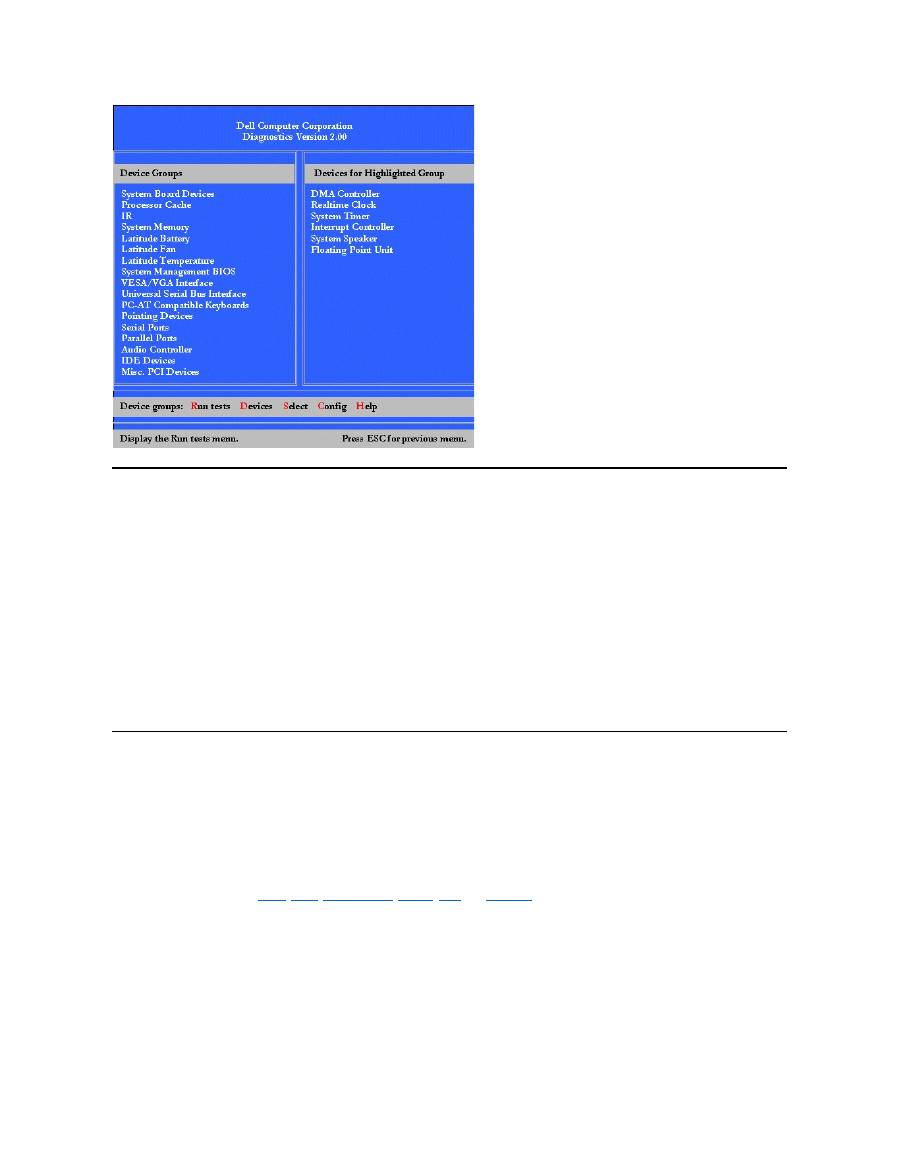
Dell Diagnostics Main Screen Overview
When you select
Select Devices to Test
from the
Diagnostics
Menu
, the main screen of the diagnostics appears (see
Figure 2
). The main
screen lists the diagnostic test device groups, lists the devices of the selected device group, and allows you to select categories from a menu.
From this screen, you can enter two other types of screens.
Information on the main screen of the diagnostics is presented in the following five areas:
l
Two lines at the top of the screen identify the version number of the Dell Diagnostics.
l
On the left side of the screen, the
Device
Group
s area lists the diagnostic test groups in the order they will run if you select
All
from the
Run
tests
menu. Press the up- or down-arrow key to highlight a test device group.
l
On the right side of the screen, the
Devices for Highlighted Group
area lists the computer's currently detected hardware and some of the
relevant settings.
l
The lower-right side of the screen displays information about your drive(s).
l
Two lines at the bottom of the screen make up the menu area. The first line lists the categories you can select; press the left- or right-arrow
key to highlight a menu category. The second line gives information about the category currently highlighted.
Figure 2. Dell Diagnostics Main Screen
NOTE: Before you read the rest of this subsection, you may want to start the Dell Diagnostics so that you can see it on your display.
NOTE: The options displayed on your screen should reflect the hardware configuration of your computer.
Confirming the System Configuration Information
When you boot your computer from your diagnostics diskette, the diagnostics checks your system configuration information and displays it in the
Device Groups
area on the main screen.
The following sources supply this configuration information for the diagnostics:
l
The system configuration information settings (stored in nonvolatile random-access memory [NVRAM]) that you selected while using the
System Setup program
l
Identification tests of the microprocessor, the video controller, the keyboard controller, and other key components
l
Basic input/output system (BIOS) configuration information temporarily saved in RAM
Do not be concerned if the
Device Groups
area does not list the names of all the components or devices you know are part of your computer. For
example, you may not see a printer listed, although you know one is attached to your computer. Because your printer is a parallel communications
device, the computer recognizes the printer by its LPT1 address and identifies it as a parallel port. You can test your printer connection in the
Parallel Ports
tests.
How to Use Dell Diagnostics
Six comprehensive, menu-driven, online Help categories provide instructions on how to use the program and explain each menu item, test group,
subtest, and test and error result. To enter the
Help
menu, perform the following steps:
1. Highlight
Select Devices to Test
in the
Diagnostics
Menu
.
2. Press <Enter>.
3. Press <h>.
The
Help
menu categories are
Menu
,
Keys
,
Device
Group
,
Device
,
Test
, and
Versions
. The online Help also provides detailed descriptions of
the devices that you are testing. The
Help
categories are explained in the following subsections.
Menu Category
Menu
describes the main menu screen area, the
Device
Groups
, and the different diagnostic menus and commands and instructions on how to
use them.
Keys Category
Keys
explains the functions of the all of the keystrokes that can be used in Dell Diagnostics.
Device Group Category

Device Group
describes the test group that is presently highlighted in the
Device
Groups
list on the main menu screen. It also provides
reasoning for using some tests.
Device Category
Device
is the educational section of online Help. It describes the function and purpose of the highlighted device in the
Device
Groups
.
For example, the following information appears when you select
Device
for
Diskette
in the
Device
Groups
list:
Diskette drive A:
The diskette disk drive device reads and writes data to and from diskettes. Diskettes are flexible
recording media, sometimes contained in hard shells. Diskette recording capacities are small and
access times are slow relative to hard disk drives, but they provide a convenient means of storing
and transferring data.
Test Category
Test
provides a thorough explanation of the subtest for each selected device group. For example, the following description is provided for the
Diskette Drive Seek Test
:
Diskette drive A: - Diskette Drive Seek Test
This test verifies the drive's ability to position its read/write heads. The test operates in two
passes: first, seeking from the beginning to ending cylinders inclusively, and second, seeking
alternately from the beginning to ending cylinders with convergence towards the middle.
Versions Category
Versions
lists the version numbers of the subtests that are used by the Dell Diagnostics.
Back to Contents Page

Back to Contents Page
Diskette Drive: Dell™ Latitude™ CS/CS x Portable Computers User's Guide
Your computer was shipped with a 3.5-inch diskette drive installed in the external media bay. For more information on using and installing devices
in the external media bay, see "
Using the External Media Bay
."
The diskette drive lets you install programs and transfer data using 3.5-inch diskettes.
To use the diskette drive, insert a 3.5-inch diskette into the drive (label side up and metal end first). Push the diskette into the drive until the eject
button extends outside the drive casing.
NOTICE:
Do not travel with a diskette in the diskette drive. Doing so could break the eject button and damage the drive.
To remove a diskette from the drive, press the eject button to release the diskette, and then pull the diskette out of the drive.
When data is being accessed from the diskette drive, the
drive access indicator
blinks.
Back to Contents Page
NOTE: As an alternative diskette drive configuration, you can
connect the diskette drive to the parallel connector
on the back of the
computer using an optional cable available from Dell. If you are running either the Microsoft
®
Windows
®
95 or Windows 98 operating
system on your computer and the
Diskette Reconfig
option is enabled in the System Setup program, you do not have to reboot the
computer when you connect the diskette drive to the parallel connector. If you are running the Microsoft Windows NT
®
operating system
on your computer, reboot the computer after you connect the diskette drive.

Back to Contents Page
Display: Dell™ Latitude™ CS/CS x Portable Computers User's Guide
Adjusting the Brightness
To adjust the brightness of the display, you can use the key combinations shown in
Table 1
.
Table 1. Brightness Key Combinations and Their Functions
Expanded Video Mode
When working in text mode, you can select the font used to display text. Press <Fn><F7> to toggle between regular video mode and expanded
video mode. In expanded video mode, items in resolutions other than 1024 x 768 expand to fill the screen, which is useful if you are working in 800
x 600 resolution on a 13.3-inch extended graphics array (XGA) display.
Video Drivers and Video Resolution
The Dell-installed video drivers work with the operating system to let you customize the video resolution, number of screen colors, and refresh rate
of your display.
Table 2. Combinations of Resolutions and Colors Supported
Adjusting the Brightness
Customizing Video Resolution
Expanded Video Mode
Dual-Display Mode
Video Drivers and Video Resolution
If You Have Display Problems
NOTE: When you run the computer on battery power, set your computer's brightness control to the lowest setting that affords
comfortable viewing. You can extend your battery life by using the minimum brightness setting.
Key Combinations
Function
<Fn> + down arrow
Decreases brightness
<Fn> + up arrow
Increases brightness
<Fn> + right arrow
Has no effect on this computer
<Fn> + left arrow
Has no effect on this computer
NOTES: You cannot change contrast on an active-matrix (thin film transistor [TFT]) display, such as your computer's display.
(Contrast
adjustments are only necessary on older passive-matrix displays.)
To use key combinations on an external keyboard, enable the
External Hot Key
option in the System Setup program and use <Scroll
Lock> instead of <Fn>.
NOTES: You may have difficulty using the display fonts feature with MS-DOS
®
programs that use downloaded fonts.
For optimum video performance in these cases, do not use expanded video mode.
NOTE: The Dell-installed video drivers are designed to offer the best performance on your computer. Dell recommends that you use
only these drivers with your factory-installed operating system.
Resolution
Colors
Bits
Display Refresh
Rate
External Monitor
Refresh Rate
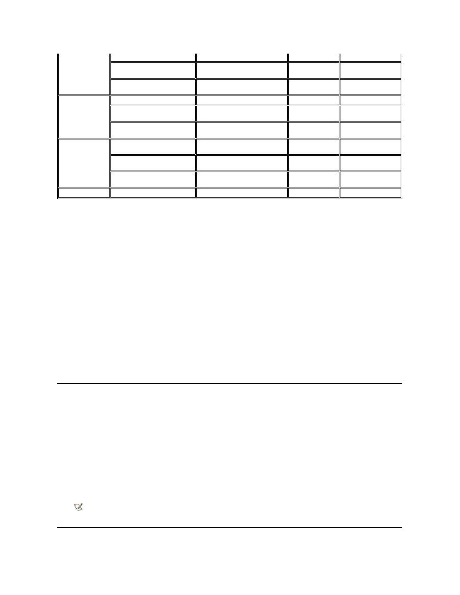
* In this resolution, the display is set to pan mode. To use 1280 x 1024 resolution, set the external monitor to
Plug and Play Monitor
as
described in the following procedures.
For Windows 95, perform the following steps:
1.
Click the
Start
,button, point to
Settings
, and then click
Control Panel
.
2.
Double-click the
Display
icon.
3.
Click the
Settings
tab, click
Advanced Properties
, and click the
Monitor
tab.
4.
Click
Change...
, click
Plug and Play Monitor
, and click
OK
twice.
5.
Set
Display area
to
1280 x 1024
, and click
OK
.
For Windows 98, perform the following steps:
1.
Click the
Start
button, point to
Settings
, and then click
Control Panel
.
2.
Double-click the
Display
icon.
3.
Click the
Settings
tab, click
Advanced...
, and click the
Monitor
tab.
4.
Click
Change...
, click
Next
, and click
Display a list of all the drivers
.
5.
Click
Next
, and click
Show all hardware
.
6.
Under
Manufacturers
, click
(Standard monitor types)
.
7.
Under
Models
, click
Plug & Play Monitor
; and click
Next
.
8.
Click
Next
again, click
Finish
, and click
Close
.
9.
At the
Display Properties
screen, set
Screen area
to
1280 x 1024
, and click
Apply
.
10.
Click
OK
, click
Yes
, and click
OK
.
To display more colors, select a lower resolution. If you select a resolution and color combination that the computer does not support, the computer
automatically selects the next supported combination.
Customizing Video Resolution
1. Click the
Start
button, point to
Settings
, and then click
Control Panel
.
The
Control Panel
window appears.
2. Double-click the
Display
icon.
The
Display Properties
window appears.
3. Click the
Settings
tab, and then set the resolution by dragging the slider in the
Desktop Area
box. In the
Color Palette
box, choose the
number of colors from the menu provided. For more information, see your operating system documentation.
If you choose a resolution or color palette that is higher than is supported, the settings adjust automatically to the closest possible setting.
4. To change the refresh rate, click the
NeoMagic
tab, and then follow the instructions on your display.
640 x 480
256
8
60 Hz
60 Hz, 75 Hz, 85 Hz
65,536
(64 K)
16 (High Color)
60 Hz
60 Hz, 75 Hz, 85 Hz
1677721
(16 Million)
24 (True Color)
60 Hz
60 Hz, 75 Hz, 85 Hz
800 x 600
256
8
60 Hz
60 Hz, 75 Hz, 85 Hz
65,536
(64 K)
16 (High Color)
60 Hz
60 Hz, 75 Hz, 85 Hz
1677721
(16 Million)
24 (True Color)
60 Hz
60 Hz, 75 Hz, 85 Hz
1024 x 768
256
8
60 Hz
60 Hz, 70 Hz, 75 Hz, 85
Hz
65,536
(64 K)
16 (High Color)
60 Hz
60 Hz, 70 Hz, 75 Hz, 85
Hz
1677721
(16 Million)
24 (True Color)
60 Hz
60 Hz, 70 Hz, 75 Hz, 85
Hz
1280 x 1024*
256
8
60 Hz
60 Hz
NOTE: You can adjust the refresh rate only on an external monitor. If the
NeoMagic
tab is inactive, your external monitor adjusts
the refresh rate automatically.

Dual-Display Mode
With Microsoft
®
Windows
®
98 and later operating systems, you can use an external monitor as an extension of your display (see your operating
system documentation for more information). To set up your computer for dual
-display mode, perform the following steps:
1. Connect the
external monitor
.
2. Click the
Start
button, point to
Settings
, and then click
Control Panel
.
3. In the
Control Panel
window, double-click the
Display
icon.
4. In the
Display Properties
window, click the
Settings
tab.
5. Change the
Colors
option to
High Color (16 bit)
.
6. Change the
Desktop Area
to
1024 by 768 pixels
.
7. Click
Advanced...
.
8. Click the
NeoMagic
tab.
9. Select the
Set Dual-Display
checkbox and click
Apply
.
10. Click
Yes
when prompted to restart your computer.
11. Click the
Start
button, point to
Settings
, and then click
Control Panel
.
12. Double-click
Display
, and then click the
Settings
tab.
Two display icons appear in the
Settings
window.
13. Click the display icon marked "
2
."
14. When asked if you want to enable this monitor, click
Yes
.
15. Click
Apply
, and then click
OK
.
If You Have Display Problems
If your computer is receiving power, but nothing appears on your display (such as light, text, or graphics) or the display image does not appear as
you would expect, try the following measures to resolve the problem:
1. If the display is blank, you may be in suspend, standby, or suspend-to-disk mode. Press the power button to resume. If the display is blank
and the power indicator is on, the display may have timed out. In this case, press any key on the keyboard to resume normal operation.
2. If the
low-battery warning
occurs,
connect
the AC adapter to the computer or replace the battery.
3. Adjust the brightness.
4. If your computer is attached to an external monitor, press <Fn><F8> to switch the video image to the display.
Back to Contents Page
NOTE: It takes several seconds to switch the video image.

Back to Contents Page
Drivers: Dell™ Latitude™ CS/CS x Portable Computers User's Guide
Back to Contents Page
Installing Microsoft
®
Windows
®
95 and Windows 98 Drivers
Installing Microsoft
®
Windows NT
®
Drivers
NOTE: For more information on using the operating system installed on your computer by Dell, see the operating system user's guide
that came with your computer.

Back to Contents Page
Error Messages and Flash Codes: Dell™ Latitude™ CS/CS x Portable Computers User's Guide
Error Messages
Your application programs, operating system, and the computer itself can identify problems and alert you to them. When this occurs, a message
may appear on the computer's display or on an external monitor (if one is attached), or a flash code may be emitted.
If an error message appears on the display or external monitor, make a note of the message. For an explanation of the message and suggestions
for correcting any errors, see
Table 1
. The messages are listed alphabetically.
Table 1. System Error Messages
Error Messages
Memory Allocations
System Flash Codes
I/O Memory Map
Avoiding Interrupt Assignment Conflicts
NOTE: If the message is not listed in Table 1, see the documentation for the application program or the operating system
documentation for an explanation of the message and a recommended action.
Message
Cause
Action
Auxiliary device
failure
The touch pad or external PS/2 mouse
may be faulty.
If you are using an external mouse only, check the connection for a
loose or improperly connected cable. If the problem persists,
enable the
Pointing Device
option. If the problem persists,
call
Dell
for technical assistance.
Bad command or file
name
The command you entered does not
exist or is not in the pathname you
specified.
Make sure that you have typed the command correctly, placed
spaces in the proper location, and used the correct pathname.
Cache disabled due to
failure
The primary cache internal to the
microprocessor has failed.
Call Dell
for technical assistance.
CD-ROM drive
controller failure 1
The CD-ROM drive does not respond to
commands from the computer.
Turn off the computer and detach the CD-ROM drive from the
media bay connector. Reboot the computer. Turn off the computer
again, reattach the CD-ROM drive to the computer, and verify the
media-bay cable connection to the back of the CD-ROM drive.
Reboot the computer. If the problem persists, run the
CD-ROM
Drive
tests in the
Dell Diagnostics
.
Data error
The diskette or hard-disk drive cannot
read the data.
Run the appropriate utility to check the file structure of the diskette
drive or hard-disk drive. See the documentation that came with
your operating system.
Decreasing available
memory
One or more memory modules may be
faulty or improperly seated.
Reseat the
memory module
in the upgrade socket. If the problem
persists, remove the memory module from the upgrade socket. If
the problem still persists,
call Dell
for technical assistance.
Disk C: failed
initialization
The hard-disk drive failed initialization.
Remove and reseat the
hard-disk drive
, and reboot the computer.
If the problem persists, boot from the
diagnostics diskett
e and run
the
Hard-Disk Drive
tests.
Diskette drive 0 seek
failure
A cable may be loose, or the system
configuration information may not match
the hardware configuration.
Check and reseat the diskette drive cable. If the problem persists,
run the
Diskette Drive
tests in the
Dell Diagnostics
and check the
setting for the appropriate drive (
Diskette Drive A
or
Diskette
Drive B
) in the
System Setup program
. If the problem cannot be
corrected, call Dell for technical assistance
.
Diskette read failure
A cable may be loose, or the diskette
may be faulty.
If the diskette-drive access indicator lights up, try a different
diskette.
Diskette subsystem
reset failed
The diskette drive controller may be
faulty.
Run the
Diskette Drive
tests in the
Dell Diagnostics
.
Diskette write-
protected
Because the diskette is write-protected,
the operation cannot be completed.
Slide the write-protect notch up.
Drive not ready
No diskette is in the diskette drive, or no
hard-disk drive is in the drive bay. The
operation requires a diskette in the drive
Put a diskette in the drive, or push the diskette all the way into the
drive until the eject button pops out. Or, install a hard-disk drive in
the drive bay.

or a hard-disk drive in the bay before it
can continue.
Error reading PCMCIA
card
The computer cannot identify the PC
Card.
Reseat the card or try another PC Card that you know works.
Extended memory size
has changed
The amount of memory recorded in
NVRAM does not match the memory
installed in the computer.
Reboot the computer. If the error appears on the display again,
call Dell
for technical assistance.
Gate A20 failure
An installed memory module may be
loose.
Reseat the
memory module
in the upgrade socket. If the problem
persists, remove the memory module from the upgrade socket. If
the problem still persists,
call Dell
for technical assistance.
General failure
The operating system is unable to carry
out the command.
This message is usually followed by specific information
—
for
example,
Printer out of paper
. Respond by taking the
appropriate action.
Hard-disk drive
configuration error
The computer cannot identify the drive
type.
Turn off the computer, remove the drive, and boot the computer
from a bootable diskette. Then turn off the computer, reinstall the
drive, and reboot the computer. Run the
Hard-Disk Drive
tests in
the
Dell Diagnostics
.
Hard-disk drive
controller failure 0
The hard-disk drive does not respond to
commands from the computer.
Turn off the computer, remove the drive, and boot the computer
from a bootable diskette. Then turn off the computer again,
reinstall the drive, and reboot the computer. If the problem
persists, try another drive. Then run the
Hard-Disk Drive
tests in
the
Dell Diagnostics
.
Hard-disk drive
failure
The hard-disk drive does not respond to
commands from the computer.
Turn off the computer, remove the drive, and boot the computer
from a bootable diskette. Then turn off the computer again,
reinstall the drive, and reboot the computer. If the problem
persists, try another drive. Then run the
Hard-Disk Drive
tests in
the
Dell Diagnostics
.
Hard-disk drive read
failure
The hard-disk drive may be faulty.
Turn off the computer, remove the drive, and boot the computer
from a bootable diskette. Then turn off the computer again,
reinstall the drive, and reboot the computer. If the problem
persists, try another drive. Then run the
Hard-Disk Drive
tests in
the
Dell Diagnostics
.
Invalid configuration
information-please run
System Setup Program
The system configuration information
does not match the hardware
configuration. This message is most
likely to occur after a memory module is
installed.
Correct the appropriate options in the
System Setup
program.
Keyboard clock line
failure
A cable or connector may be loose, or
the keyboard may be faulty.
Run the
Keyboard Controller
test in the
Dell Diagnostics
.
Keyboard controller
failure
A cable or connector may be loose, or
the keyboard may be faulty.
Reboot the computer, and avoid touching the keyboard or the
mouse during the boot routine. If the problem persists, run the
Keyboard Controller
test in the
Dell Diagnostics
.
Keyboard data line
failure
A cable or connector may be loose, or
the keyboard may be faulty.
Run the
Keyboard Controller
test in the
Dell Diagnostics
.
Keyboard stuck key
failure
If an external keyboard or keypad is
being used, a cable or connector may be
loose or the keyboard may be faulty. If
the integrated keyboard is being used,
the keyboard may be faulty.
A key on the integrated keyboard or
external keyboard may have been
pressed while the computer was booting.
Run the
Stuck Key
test in the
Dell Diagnostics
.
Memory address line
failure at address,
read value expecting
value
An installed memory module may be
faulty or improperly seated.
Reseat the
memory module
in the upgrade socket. If the problem
persists, remove the memory module from the upgrade socket. If
the problem still persists,
call Dell
for technical assistance.
Memory allocation
error
The software you are attempting to run is
conflicting with the operating system,
another application program, or a utility.
Turn off the computer, wait 30 seconds, and then restart it. Try to
run the program again. If the problem persists, contact the
software company.
Memory data line
failure at address,
read value expecting
value
An installed memory module may be
faulty or improperly seated.
Reseat the
memory module
in the upgrade socket. If the problem
persists, remove the memory module from the upgrade socket. If
the problem still persists,
call Dell
for technical assistance.
Memory double word
logic failure at
address, read value
expecting value

System Flash Codes
When errors that occur during the boot routine cannot be reported on the display or on an external monitor (if attached), the Num Lock, Caps Lock,
and Scroll Lock indicators (see
Figure 1
) may flash together in a pattern of lights (or
flash code
) that identifies the problem. For example, one
flash, followed by a second flash, and then a burst of three flashes (code 1-1-3) means that the computer was unable to read the data in nonvolatile
random-access memory (NVRAM). This information is important to the Dell support staff if you need to call for technical assistance.
The Num Lock, Caps Lock, and Scroll Lock indicators flash briefly when the computer is turned on. The flash codes, if needed, occur after the boot
routine.
Figure 1. Flash Code Indicators
Memory odd/even logic
failure at address,
read value expecting
value
Memory write/read
failure at address,
read value expecting
value
No boot device
available
The computer cannot find the diskette or
hard-disk drive.
If the diskette drive is your
boot device
, make sure that there is a
bootable diskette in the drive. If the hard-disk drive is your boot
device, make sure that the drive is installed, properly seated, and
partitioned as a boot device.
No boot sector on
hard-disk drive
The operating system may be corrupted.
Reinstall your operating system. See the documentation that came
with your operating system.
No timer tick
interrupt
A chip on the system board may be
malfunctioning.
Run the
System Set
tests in the
Dell Diagnostics
.
Non-system disk or
disk error
The diskette in drive A or your hard-disk
drive does not have a bootable
operating system installed on it.
If you are trying to boot from the diskette, replace it with one that
has a bootable operating system.
Not a boot diskette
There is no operating system on the
diskette.
Boot the computer with a diskette that contains an operating
system.
Optional ROM bad
checksum
The optional ROM apparently failed.
Call Dell
for technical assistance.
Sector not found
The operating system cannot locate a
sector on the diskette or hard-disk drive.
You probably have a bad sector or
corrupted FAT on the diskette or hard-
disk drive.
Run the appropriate utility to check the file structure on the diskette
or hard-disk drive. If a large number of sectors are defective, back
up the data (if possible), and then reformat the diskette or hard-
disk drive.
Seek error
The operating system cannot find a
specific track on the diskette or hard-
disk drive.
If the error is on the diskette drive, try another diskette in the drive.
Shutdown failure
A chip on the system board may be
malfunctioning.
Run the
System Set
tests in the
Dell Diagnostics
.
Time-of-day clock lost
power
Data stored in NVRAM has become
corrupted.
Connect your computer to an electrical outlet to charge the battery.
If the problem persists, try to restore the data. To restore the data,
press <Fn><F1> to
enter the System Setup program
. Then
immediately exit it. If the message reappears,
call Dell
for
technical assistance.
Time-of-day clock
stopped
The reserve battery that supports the
data stored in NVRAM may be dead.
Connect your computer to an electrical outlet to charge the battery.
If the problem persists,
call Dell
for technical assistance.
Time-of-day not set-
please run the System
Setup program
The time or date stored in the System
Setup program does not match the
system clock.
Correct the settings for the
Date
and
Time
options. (For
instructions, see "
System Setup Program
.")
Timer chip counter 2
failed
A chip on the system board may be
malfunctioning.
Run the
System Set
tests in the
Dell Diagnostics
.
Unexpected interrupt
in protected mode
The keyboard controller may be
malfunctioning, or an installed memory
module may be loose.
Run the
System Memory
tests and the
Keyboard Controller
test in the
Dell Diagnostics
.
Warning: Battery is
critically low.
The battery is running out of charge.
Replace the
battery
, or connect the computer to an electrical
outlet. Otherwise, activate
suspend-to-disk
mode or turn off the
computer.
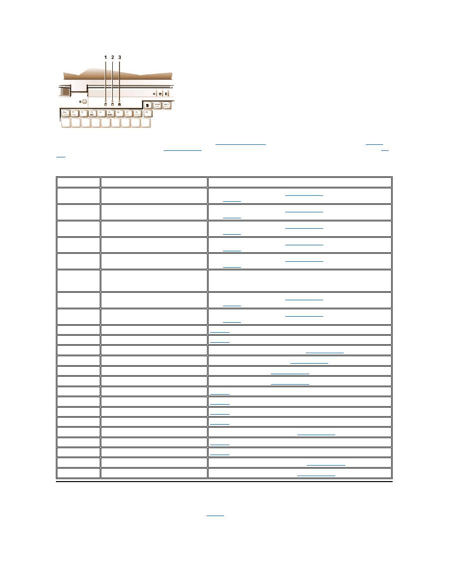
When the computer emits a flash code, write it down on a copy of the
Diagnostics Checklist
and then look up its cause and meaning in
Table 2
. If
you are unable to resolve the problem, use the
Dell Diagnostics
to identify a more serious cause. If you are still unable to resolve the problem,
call
Dell
for technical assistance.
Table 2. Flash Codes and Corrective Actions
Avoiding Interrupt Assignment Conflicts
Problems can arise if two devices attempt to use the same interrupt request (IRQ) line. To avoid this type of conflict, check the documentation for
the default IRQ line setting for each installed device. Then consult
Table 3
to configure the device for one of the available IRQ lines.
1
Num Lock
2
Caps Lock
3
Scroll Lock
Message
Cause
Action
1-1-3
NVRAM write/read failure.
Run the
System Set
tests in the
Dell Diagnostics
. If the program does not
load,
call Dell
for technical assistance.
1-1-4
ROM BIOS checksum failure.
Run the
System Set
tests in the
Dell Diagnostics
. If the program does not
load,
call Dell
for technical assistance.
1-2-1
Programmable interval timer failure.
Run the
System Set
tests in the
Dell Diagnostics
. If the program does not
load,
call Dell
for technical assistance.
1-2-2
DMA initialization failure.
Run the
System Set
tests in the
Dell Diagnostics
. If the program does not
load,
call Dell
for technical assistance.
1-2-3
DMA page register write/read failure.
Run the
System Set
tests in the
Dell Diagnostics
. If the program does not
load,
call Dell
for technical assistance.
1-3-1
through
2-4-4
An installed memory module is not being
properly identified or used.
Make sure that a memory module is installed in one of the memory module
sockets on the system board. The computer will not function unless at least
one memory module is installed.
3-1-1
Slave DMA register failure.
Run the
System Set
tests in the
Dell Diagnostics
. If the program does not
load,
call Dell
for technical assistance.
3-1-2
Master DMA register failure.
Run the
System Set
tests in the
Dell Diagnostics
. If the program does not
load,
call Dell
for technical assistance.
3-1-3
Master interrupt mask register failure.
Call Dell
for technical assistance.
3-1-4
Slave interrupt mask register failure.
Call Dell
for technical assistance.
3-2-4
Keyboard controller test failure.
Run the
Keyboard Controller
test in the
Dell Diagnostics
.
3-3-4
Display memory test failure.
Run the
Video Memory
test in the
Dell Diagnostics
.
3-4-1
Display initialization failure.
Run the
Video
tests in the
Dell Diagnostics
.
3-4-2
Display retrace test failure.
Run the
Video
tests in the
Dell Diagnostics
.
4-2-1
No timer tick.
Call Dell
for technical assistance.
4-2-2
Shutdown failure.
Call Dell
for technical assistance.
4-2-3
Gate A20 failure.
Call Dell
for technical assistance.
4-2-4
Unexpected interrupt in protected mode.
Call Dell
for technical assistance.
4-3-1
Memory failure above address 0FFFFh.
Run the
System Memory
tests in the
Dell Diagnostics
.
4-3-3
Timer chip counter 2 failure.
Call Dell
for technical assistance.
4-3-4
Time-of-day clock stopped.
Call Dell
for technical assistance.
4-4-1
Serial port failure.
Run the
Serial/Infrared Ports
tests in the
Dell Diagnostics
.
5-1-2
No usable memory.
Run the
System Memory
tests in the
Dell Diagnostics
.
Table 3. IRQ Line Assignments
Memory Allocations
Table 4
provides a map of the conventional memory area. When the microprocessor or a program addresses a location within the conventional
memory range, it is physically addressing a location in main memory.
Table 4. Conventional Memory Map
Table 5
provides a map of the upper memory area. Some of these addresses are dedicated to various system devices, such as the system/video
basic input/output system (BIOS). Others are available for use by expansion cards and/or an expanded memory manager (EMM).
When the microprocessor or a program addresses a location within the upper memory area, it is physically addressing a location within one of
these devices.
Table 5. Upper Memory Map
NOTES: Installed devices cannot share the same COM port address. The default address of your computer's serial port is COM1.
To view IRQ line assignments in the Microsoft
®
Windows
®
95 and Windows 98 operating systems, click the
Start
button, point to
Settings
, and click
Control Panel
. Double-click the
System
icon. Select the
Device Manager
tab, and then double-click
Computer
.
IRQ Line Reserved/Available
IRQ0
Reserved; generated by the system timer
IRQ1
Reserved; generated by the keyboard controller to signal that the keyboard output buffer is full
IRQ2
Reserved; generated internally by the interrupt controller to enable IRQ8 through IRQ15
IRQ3
Available for use by a PC Card unless the integrated serial port or infrared port is configured for COM2 or COM4
IRQ4
Available for use by a PC Card unless the integrated serial port or infrared port is configured for COM1 (the default) or COM3
IRQ5
Available for use by the audio controller
IRQ6
Generated by the diskette drive controller to indicate that the diskette drive requires the attention of the microprocessor
IRQ7
Available for use by a PC Card or audio controller if the parallel port is disabled
IRQ8
Reserved; generated by the system I/O controller's RTC
IRQ9
Reserved
IRQ10
Available for use by a PC Card or audio controller unless the C/Port Family APR or C/Dock Family Expansion Station is attached
IRQ11
Available for use by USB, PC Card, video controller, and audio controller
IRQ12
Reserved; generated by the keyboard controller to indicate that the output buffer of the touch pad or external PS/2 mouse is full
IRQ13
Reserved; generated by the math coprocessor
IRQ14
Reserved; generated by the hard-disk drive to indicate that the drive requires the attention of the microprocessor
IRQ15
Reserved; generated by CD-ROM drive in the external media bay to indicate that the drive requires the attention of the
microprocessor
NOTE: To view memory allocations in Windows 95 and Windows 98, click the
Start
button, point to
Settings
, and click
Control Panel
.
Double-click the
System
icon. Click the
Device Manager
tab, and then double-click
Computer
.
Address Range
Use
0000h-003FFh
Interrupt vector table
00400h-004FFh
BIOS data area
00500h-005FFh
MS-DOS
®
and BASIC work area
00600h-9FBFFh
User memory
Address Range
Use
0009FC00-0009FFFF
PS/2-mouse data area
000A0000-000BFFFF
Video RAM
000C0000-000CBFFF
Video BIOS
000CC000-000CDFFF
PC Card
000F0000-000FFFFF
System BIOS
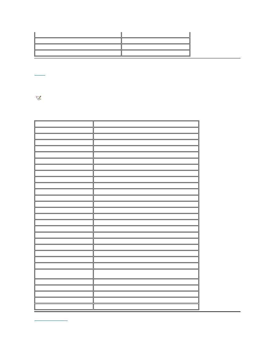
I/O Memory Map
Table 6
provides a map of memory addresses reserved by the computer for peripheral input/output (I/O) devices. Use the information in Table 6 to
determine if the memory address of an external device (such as a PC Card) conflicts with a memory address reserved by the computer.
Check the documentation of the external I/O device to determine its memory address. If a device's memory address conflicts with a memory
address reserved by the computer, change the address of the device.
Table 6. I/O Memory Map
Back to Contents Page
00100000-03FFFFFF
High memory area
FD000000-FDFFFFFF (approximate; not a fixed location)
Video RAM
FF200000-FF2FFFFF (approximate; not a fixed location)
Video RAM
FFFE0000-FFFFFFFF
BIOS ROM
NOTE: To view I/O addresses in Windows 95 and Windows 98, click the
Start
button,
point to
Settings
, and click
Control Panel
. Double-click the
System
icon. Click the
Device Manager
tab, and then double-click
Computer
.
Address
Device
0000-001F
DMA controller #1
0020-003F
Interrupt controller #1
0040-005F
System timers
0060-0060
Keyboard controller
0061-0061
System speaker
0064-0064
Keyboard controller
0070-007F
RTC and NMI enable
0080-009F
DMA page registers
00A0-00BF
Interrupt controller #2
00C0-00DF
DMA controller #2
00F0-00FF
Math coprocessor
0170-0177
CD-ROM drive controller
01F0-01F7
Hard-disk drive controller
0210-0217
Audio controller
0220-022F
Audio controller
0270-0277
Fast IR
0376-0376
IDE controller
0378-037F
LPT1
0388-038B
Audio controller
03B0-03BB
VGA
03C0-03DF
VGA
03E0-03E1
PC Card controller
03E8-03EF
Fast IR
03F2-03F5;
03F7-03F7
Diskette controller
03F8-03FF
COM1
0530-0537
Audio controller
0778-077B
ECP registers
ECE0-ECFF
USB controller
FFA0-FFAF
PCI-IDE bus registers

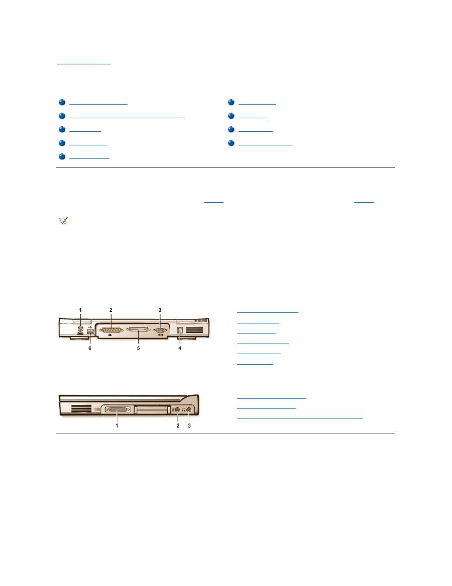
Back to Contents Page
Connecting External Devices: Dell™ Latitude™ CS/CS x Portable Computers User's Guide
About the I/O Connectors
You can connect external devices to the input/output (I/O) connectors. The computer's basic input/output system (BIOS) detects the presence of
external devices when you boot (start) or reboot your computer.
Figure 1
shows the I/O connectors on the back of your computer;
Figure 2
shows
the external media bay and audio connectors on the right side of the computer.
Figure 1. I/O Connectors On the Back of the Computer
Figure 2. I/O Connectors On the Right Side of the Computer
Mouse, Keyboard, and External Numeric Keypad
You can attach a PS/2-compatible device such as a mouse, 101- or 102-key keyboard, or external numeric keypad to the mini-Deutsche Industrie
Norm (DIN) PS/2 connector.
You can also connect these devices to the C/Port Family APR or the C/Dock Family Expansion Station.
About the I/O Connectors
External Monitor
Mouse, Keyboard, and External Numeric Keypad
AC Adapter
USB Devices
Audio Devices
Parallel Devices
External Media Options
Docking Devices
NOTES: Some external devices require you to load software called device drivers into system memory before the devices will work.
These device drivers help your computer recognize the external device and direct its operation. Instructions for installing this software
are usually included in the upgrade kits.
The C/Port Family Advanced Port Replicator (APR) has the same I/O connectors as your computer. In addition, the C/Port APR has a
second Personal System/2 (PS/2) connector, a second Universal Serial Bus (USB) connector, and an Ethernet network connector.
The C/Dock Family Expansion Station has the same I/O connectors as your computer. In addition, the C/Dock Expansion Station has a
second PS/2 connector, a second USB connector, an Ethernet network connector, and a small computer system interface (SCSI)
connector.
1
PS/2 (mini-DIN) connector
2
Parallel connector
3
Video connector
4
AC adapter connector
5
Docking connector
6
USB connector
1
External media bay connector
2
Microphone (MIC IN) jack
3
Speakers and headphones (line-out/speaker-out) jack

Mouse
When you attach a PS/2 mouse to the computer, the touch pad is automatically disabled. If you disconnect the mouse, you must shut down the
computer or enter suspend or standby mode and then resume from it before the touch pad is operational. If you do not do this, the touch pad
resumes operation in standard PS/2 mode, which means that many of the configuration features are disabled.
If you are using a PS/2-compatible mouse that is not made by Microsoft and the mouse does not work properly, reboot the computer. If the mouse
still does not work, install the drivers from the diskette that came with the mouse and reboot the computer.
Keyboard
You can use the computer's keyboard and an external keyboard at the same time. When you attach a keyboard to the computer, the embedded
numeric keypad is automatically disabled.
On an external keyboard, the <Scroll Lock> key acts the same way as the <
Fn> key on the computer’
s keyboard (if the
External Hot Key
option is
enabled in the System Setup program).
External Numeric Keypad
When you attach an external numeric keypad to the computer, the numeric keypad on the computer keyboard is automatically disabled. The
indicators on the integrated keyboard track the operation of an external numeric keypad.
USB Devices
You can attach a USB hub device to the USB connector. The USB hub device can support multiple USB devices (typically low-speed peripherals
such as mice, keyboards, printers, and computer speakers). The C/Port APR Family and the C/Dock Expansion Station Family docking solutions
have two USB connectors.
Parallel Devices
You can attach a parallel device (usually a printer) to the 25-hole parallel connector. You can also connect the diskette drive to the parallel
connector.
The parallel port sends and receives data in parallel format, where eight data bits (one byte) are sent simultaneously over eight separate lines. The
port can be configured as a unidirectional (output-only) port for devices such as a printer or as a bidirectional port for devices such as a network
adapter.
The computer's integrated parallel port is designated as LPT1. The Microsoft
®
Windows
®
95 and Windows 98 operating systems automatically
recognize the parallel device and configure it correctly. The parallel port can also be configured for compatibility with the PS/2 standard.
Connecting a Diskette Drive to the Parallel Connector
You can use the the diskette drive as a second external device if you already have a device connected to the media bay connector. The diskette
drive letter is A, unless a diskette drive is already installed in the external media bay, in which case the drive connected to the parallel connector is
NOTE: If the computer is in suspend (or standby) or suspend-to-disk mode when you attach a mouse, you can use the mouse when the
computer resumes normal operation. However, programs that were already running may need to be restarted to recognize the mouse. If
the computer is not in suspend (or standby) or suspend-to-disk mode when you attach the mouse, you must reboot the computer to use
the mouse.
NOTE: If the computer is in suspend (or standby) mode or suspend-to-disk mode when you attach an external keyboard, the device is
recognized immediately by the computer when it resumes normal operation.
NOTE: If the computer is in suspend (or standby) mode or suspend-to-disk mode when you attach an external numeric keypad, the
device is recognized immediately by the computer when it resumes normal operation.
NOTE: If you are using a USB external keyboard, do not enter the System Setup program by using a keyboard command on an
external keyboard. Instead, press <Fn><F1> on the computer's keyboard.
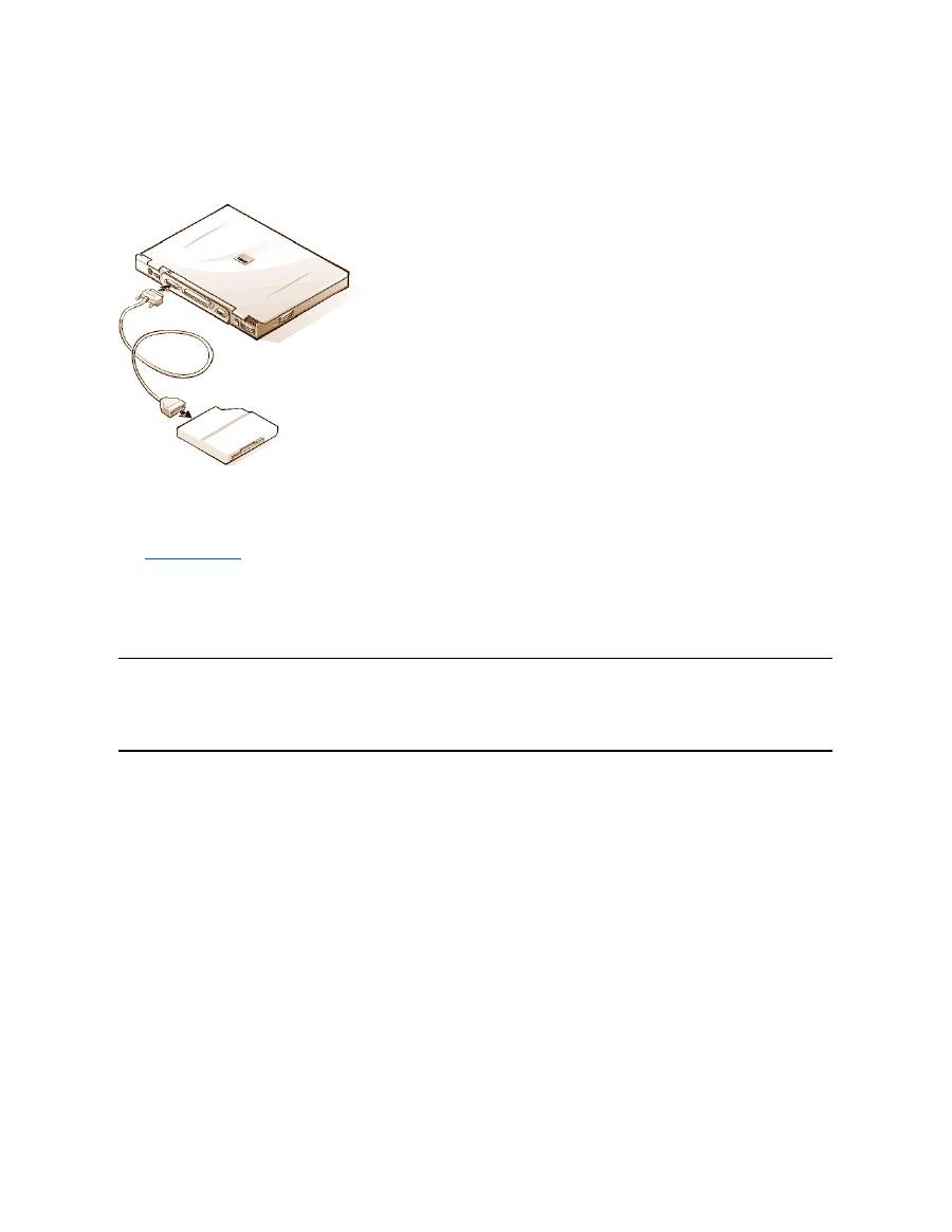
drive B.
To connect the drive to the parallel connector on the I/O panel, use the optional parallel diskette-drive cable (available from Dell), as shown in
Figure 5.
Figure 5. Connecting a Diskette Drive to the Parallel Connector
NOTICE: When the diskette drive is not being used externally, remove the parallel diskette-drive cable from the parallel connector.
NOTICE: Use the parallel diskette-drive cable only with the diskette drive. Do not try to connect any other device to the computer
with this cable.
If the
Diskette Reconfig
option is set to
Any Time
in the System Setup program, you can connect the diskette drive to the parallel connector while
the computer is turned on.
The drive access indicator does not blink when data is being accessed from the diskette drive connected to the parallel connector.
NOTICE: Protect the diskette drive when it is not in the external media bay. Do not squeeze the drive or place objects on top of it;
doing so could damage the drive motor.
Docking Devices
You can attach your computer to Dell's C/Port Family APR and C/Dock Family Expansion Station docking devices through the docking connector.
For information on docking your computer, see the documentation that came with your docking device.
External Monitor
You can use the 15-hole video connector to attach an external monitor to the computer.
Connecting an External Monitor
To attach an external monitor, perform the following steps.
NOTICE: Do not place the monitor directly on top of your portable computer, even if it is closed. Doing so can crack the computer
case, the display, or both.
1. Make sure that the external monitor is turned off. Set the monitor on a monitor stand, desk top, or other level surface near your computer.
2. Connect the external monitor's video cable to the computer.
Plug the video cable connector into the matching video connector on the back of the computer, as shown in Figure 6. If the video cable
is not permanently attached to the monitor, connect it to the monitor.
Figure 6. Connecting an External Monitor

Be sure to tighten all the screws on the video cable connector(s) to eliminate radio frequency interference (RFI).
3. Connect your external monitor to a grounded electrical outlet.
Plug the three-prong connector on one end of the monitor's power cable into a grounded power strip or some other grounded power
source. If the cable is not permanently attached to the monitor, connect it to the monitor.
You can also connect an external monitor to the C/Port Family APR or the C/Dock Family Expansion Station.
Using an External Monitor
When an external monitor is connected to the computer, the video image automatically appears on the external monitor's screen when you boot
your computer.
To toggle the video image between the display, an external monitor, or both simultaneously, press <Fn><F8> on the keyboard. Press <Scroll
Lock><F8> on an external keyboard if the
External Hot Key
option is enabled in the System Setup program.
If the external monitor is turned off when you boot your computer, the computer still sends the video image to the external monitor, but you will not
see an image on either the computer's display or the external monitor. To see an image, turn on the external monitor or switch the video image to
the computer
’
s display by pressing <Fn><F8> on the keyboard or <Scroll Lock><F8> on an external keyboard if the
External Hot Key
option is
enabled in the System Setup program.
AC Adapter
You can attach the
AC adapter
to the computer by using the AC adapter connector. The AC adapter converts AC power to the DC power required
by the computer.
You can connect the AC adapter with your computer turned either on or off.
The AC adapter works with electrical outlets worldwide. However, power connectors vary among countries. Before using AC power in a foreign
country, you may need to obtain a new power cable designed for use in that country.
Audio Devices
You can connect audio devices such as speakers, microphones, and headphones to the two
audio jacks
, as follows:
l
Connect the audio cable from a microphone to the microphone jack, also called the MIC IN jack.
l
Connect the audio cable
from speakersto the headphones/speakers jack, also called the line-out/speaker-out jack.
If your computer is running the Windows 95 operating system, you can control the sound on your computer through the
Dell Control Center
Speaker
window, the
System Setup
program, and
key combinations
.
External Media Options
You can connect
external media options
such CD-ROM, DVD-ROM, SuperDisk LS-120, and diskette drives to the external media bay connector.
Back to Contents Page
NOTE:
If you are using the Microsoft Windows 98 operating system, you can use an external monitor as an extension of your
display. For more information, see the Windows 98 documentation or "
Dual-Display Mode
."
NOTE: If you are using your external monitor at a resolution greater than the display supports, the simultaneous display feature is
disabled. To use the display, switch to a resolution that the computer supports, or disconnect the external monitor and restart your
computer.
NOTE: The C/Port Family APR also has a headphones/speaker jack. The C/Dock Family Expansion Station has a line
-in/audio-in jack
as well as microphone and headphones/speaker jacks.


Back to Contents Page
Getting Help: Dell™ Latitude™ CS/CS x Portable Computers User's Guide
Back to Contents Page
Help Overview
Contacting Dell

Back to Contents Page
Help Overview: Dell™ Latitude™ CS Portable Computers User's Guide
Technical Assistance
If you need assistance with a technical problem, perform the following steps:
1. Run the Dell Diagnostics as described in "
Running the Dell Diagnostics
."
2. Make a copy of the
Diagnostics Checklist
and fill it out.
3. Use Dell's extensive suite of online services available at Dell's World Wide Web site (
http://www.dell.com
) for help with installation and
troubleshooting procedures.
4. If the preceding steps have not resolved the problem and you need to talk to a Dell technician, call Dell's technical support service.
When prompted by Dell's automated telephone system, enter your Express Service Code to route the call directly to the proper support
personnel. If you do not have an Express Service Code, open the
Dell Accessories
folder, double-click the
Express Service Code
icon, and follow the directions.
For instructions on using the technical support service, refer to "
Technical Support Service
" and "
Before You Call
."
Help Tools
Dell provides a number of tools to assist you. These tools are described in the following sections.
World Wide Web on the Internet
The Internet is your most powerful tool for obtaining information about your computer and other Dell products. Through the Internet, you can access
most of the services described in this section, including AutoTech, TechFax, order status, technical support, and product information.
Everything you need to know about your system is presented on the system support page, including the following tools and information:
l
Technical information
—
Details on every aspect of your system, including hardware specifications.
l
Self-diagnostic tools
—
A system-specific troubleshooting application for resolving many computer-related issues by following interactive
flowcharts.
l
Drivers, files, and utilities
—
The latest drivers and basic input/output system (BIOS) updates to keep your system functioning at its best.
l
Component support
—
Technical information, documentation, and troubleshooting tips for different system components.
l
Online communications center
—
Tool for submitting requests for both technical and nontechnical information on Dell products. Avoid
telephone delays by receiving an e-mail response to your request for information if your computer is not functioning properly or if you have
questions regarding your computer's hardware or operation.
Dell can be accessed electronically using the following addresses:
l
World Wide Web
http://www.dell.com/
Technical Assistance
Product Information
Help Tools
Returning Items for Warranty Repair or Credit
Problems With Your Order
Before You Call
NOTE: Dell's Express Service Code system may not be available in all countries.
NOTE: Some of the following tools are not always available in all locations outside the continental U.S. Please call your local Dell
representative for information on availability.
From Dell's World Wide Web home page (
http://www.dell.com
), click the
Support
icon, and click
Support Your Dell
. Enter your service
tag number (or, if you have one, your Express Service Code) and click
Submit
. If you don't have your service tag number or Express
Service Code available, you can also select support information by system.

http://www.dell.com/ap/
(for Asian/Pacific countries only)
http://www.euro.dell.com
(for Europe only)
l
Anonymous file transfer protocol (FTP)
ftp.dell.com/
Log in as user: anonymous, and use your e-mail address as your password.
l
Electronic Support Service
mobile_support@us.dell.com
apsupport@dell.com
(for Asian/Pacific countries only)
support.euro.dell.com
(for Europe only)
l
Electronic Quote Service
sales@dell.com
apmarketing@dell.com
(for Asian/Pacific countries only)
l
Electronic Information Service
info@dell.com
AutoTech Service
Dell's automated technical support service
—
AutoTech
—
provides recorded answers to the questions most frequently asked by Dell customers.
When you call AutoTech, you use your touch-tone telephone to select the subjects that correspond to your questions. You can even interrupt an
AutoTech session and continue the session later. The code number that the AutoTech service gives you allows you to continue your session where
you ended it.
The AutoTech service is available 24 hours a day, seven days a week. You can also access this service through the technical support service. For
the telephone number to call, refer to "
Contacting Dell
."
TechFax Service
Dell takes full advantage of fax technology to serve you better. Twenty-four hours a day, seven days a week, you can call the Dell TechFax line toll-
free for all kinds of technical information.
Using a touch-tone phone, you can select from a full directory of topics. The technical information you request is sent within minutes to the fax
number you designate. For the TechFax telephone number to call, refer to "
Contacting Dell
."
TechConnect BBS
Use your modem to access Dell's TechConnect bulletin board service (BBS) 24 hours a day, seven days a week. The service is menu-driven and
fully interactive. The protocol parameters for the BBS are 1200 to 19.2K baud, 8 data bits, no parity, 1 stop bit.
Automated Order-Status System
You can call this automated service to check on the status of any Dell products that you have ordered. A recording prompts you for the information
needed to locate and report on your order. For the telephone number to call, refer to "
Contacting Dell
."
Technical Support Service
Dell's industry-leading hardware technical support service is available 24 hours a day, seven days a week, to answer your questions about Dell
hardware.
Our technical support staff pride themselves on their track record: more than 90 percent of all problems and questions are taken care of in just one
toll-free call, usually in less than 10 minutes. When you call, our experts can refer to records kept on your Dell system to better understand your
particular question. Our technical support staff use computer-based diagnostics to provide fast, accurate answers to questions.
To contact Dell's technical support service, first refer to "
Before You Call
" and then call the number for your country as listed in "
Contacting Dell
."
Problems With Your Order
If you have a problem with your order, such as missing parts, wrong parts, or incorrect billing, contact Dell for customer assistance. Have your
invoice or packing slip handy when you call. For the telephone number to call, refer to "
Contacting Dell
."

Product Information
If you need information about additional products available from Dell, or if you would like to place an order, visit Dell's World Wide Web site at
http://www.dell.com
. For the telephone number to call to speak to a sales specialist, refer to "
Contacting Dell
."
Returning Items for Warranty Repair or Credit
Prepare all items being returned, whether for repair or credit, as follows:
1. Call Dell to obtain an authorization number, and write it clearly and prominently on the outside of the box.
For the telephone number to call, refer to "
Contacting Dell
."
2. Include a copy of the invoice and a letter describing the reason for the return.
3. Include a copy of the
Diagnostics Checklist
indicating the tests you have run and any error messages reported by the Dell Diagnostics.
4. Include any accessories that belong with the item(s) being returned (power cables, so ftware diskettes, guides, and so on) if the return is for
credit.
5. Pack the equipment to be returned in the original (or equivalent) packing materials.
You are responsible for paying shipping expenses. You are also responsible for insuring any product returned, and you assume the risk of loss
during shipment to Dell. Collect On Delivery (C.O.D.) packages are not accepted.
Returns that are missing any of the preceding requirements will be refused at our receiving dock and returned to you.
Before You Call
Remember to fill out the
Diagnostics Checklist
. If possible, turn on your system before you
call Dell
for technical assistance and call from a
telephone at or near the computer. You may be asked to type some commands at the keyboard, relay detailed information during operations, or try
other troubleshooting steps possible only at the computer system itself. Make sure the system documentation is available.
Diagnostics Checklist
NOTE: Have your Express Service Code ready when you call. The code helps Dell's automated-support telephone system direct your
call more efficiently.
CAUTION: If you need to remove the computer covers, be sure to first disconnect the computer system's power and modem
cables from all electrical outlets.
Date:
Name:
Address:
Phone number:
Service tag (bar code on the back of the computer):
Express Service Code:
Return Material Authorization Number (if provided by Dell support technician):
Operating system and version:
Peripherals:
Expansion cards:
Are you connected to a network? Yes No
Network, version, and network card:
Programs and versions:

Back to Contents Page
Refer to your operating system documentation to determine the contents of the system
’
s start-up files. If the
computer is connected to a printer, print each file. Otherwise, record the contents of each file before calling Dell.
Error message, beep code, or diagnostic code:
Description of problem and troubleshooting procedures you performed:

Back to Contents Page
Introduction: Dell™ Latitude™ CS/CS x Portable Computers User's Guide
Overview
Dell Latitude CS and CS
x
portable computers are expandable multimedia systems designed around an Intel
®
Mobile Pentium
®
II microprocessor
or an Intel Mobile Pentium III microprocessor, both with Peripheral Component Interconnect (PCI) technology. This section describes the major
hardware and software features of your computer.
Figure 1
,
Figure 2
, and
Figure 3
show the front/right, back/left, and bottom views of the
computer.
Figure 4
identifies the system status and keyboard status indicators.
Figure 1. Front/Right View of the Computer
Figure 2. Back/Left View of the Computer
Overview
Available Options
Features
Getting Help
1
Display
2
System status indicators (3)
3
Integrated microphone
4
Audio jacks (2)
5
PC Card slots (2)
6
External media bay
7
Media bay cable (attached to media bay connector on
computer)
8
Speaker
9
Hard-disk drive bay
10
Display latch
11
Touch pad buttons
12
Touch pad
13
Keyboard
14
Power button
15
Keyboard status indicators (3)
1
Air vent
2
Security
cable slot
3
Air vent
4
AC adapter
connector
5
Video
connector
6
Docking
connector
7
Parallel
connector
8
USB
connector
9
PS/2
connector
10
Integrated
microphone
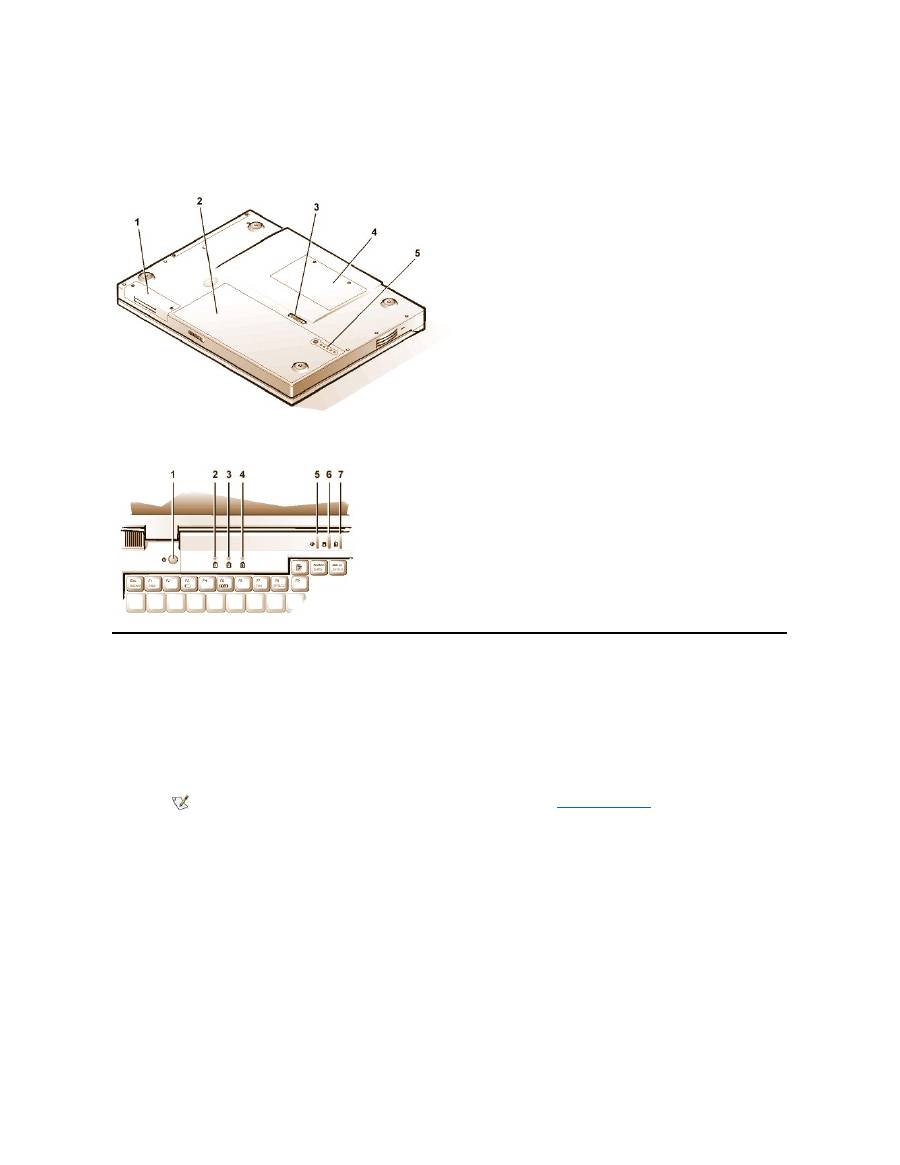
Figure 3. Bottom View of the Computer
Figure 4. Indicator Panel Features
Features
Your Dell computer provides the following features:
l
Full multimedia capability through the following standard features:
¡
A 13.3-inch extended graphics array (XGA), 1024 x 768 thin film transistor (TFT) active-matrix color display
¡
An external media bay that supports storage devices such as a DVD-ROM, CD-ROM, diskette, SuperDisk LS-120, or second hard-
disk drive
¡
256-bit hardware-accelerated video support, with 4 megabytes (MB) of video memory
¡
Accelerated graphics port (AGP) architecture that increases the computer's video performance
¡
Support for a zoomed video (ZV) PC Card in the top PC Card slot
¡
Two audio jacks for connecting a microphone and external stereo speakers or headphones
¡
Integrated microphone and speaker
¡
Software wavetable support and Sound Blaster software-emulation capability
l
System memory consisting of synchronous dynamic random-access memory (SDRAM) small outline, dual-inline memory modules
(SODIMMs). Factory
-installed memory can range from 64 MB to a system maximum of 320 MB. Depending on the memory already installed,
you may be able to increase memory by installing a 32-, 64-, or 128-MB SDRAM SODIMM in the memory upgrade socket. The achievable
memory total for your computer depends on the computer's original memory configuration.
l
Two power conservation modes
—
suspend (or standby) mode
and
suspend-to-disk mode
—
that help you conserve battery power. If the
11
System
status
indicators
1
Hard-disk drive bay
2
Battery
3
Battery latch
4
Memory module cover
5
Battery charge gauge
1
Power button
2
Num Lock indicator
3
Caps Lock indicator
4
Scroll Lock indicator
5
Power indicator
6
Drive access indicator
7
Battery status indicator
NOTE: For information on installing devices in the external media bay, see "
External Media Bay
."

batteries run out of power, suspend-to-disk mode prevents data loss by copying all system data to the hard-disk drive and turning off the
computer.
l
Connectors for two 3.3-volt (V) or 5-V PC Cards. The upper PC Card slot supports ZV PC Cards.
l
Hardware and software support for the Dell Latitude C/Port Family Advanced Port Replicator (APR) and the Dell Latitude C/Dock Family
Expansion Station.
l
A touch-pad pointing device positioned for both left- and right-handed users. The left and right touch-pad buttons mimic mouse buttons; you
can also perform many pointing functions by tapping the touch pad itself. Click-and-drag buttonless functions are supported.
l
A lithium ion battery in the battery bay. The Dell ExpressCharge
™
technology charges a single battery in approximately 1 hour (when the
computer is off or in suspend [or standby] mode).
l
A high-performance parallel port and a multipurpose Personal System/2 (PS/2) connector for attaching external devices, a monitor connector
for attaching an external monitor to your computer, and a Universal Serial Bus (USB) connector that supports stand-alone and hub devices.
l
An automatic thermal management system that uses a variable-speed fan and microprocessor speed changes to keep the system running
at the optimum temperature.
The following software is included with your Dell computer:
l
The Microsoft
®
Windows
®
95, Windows 98, or Windows NT
®
4.0 or later operating system is installed on your hard-disk drive. For more
information, see your operating system documentation.
l
The
System Setup program
lets you view and change the system configuration.
l
The Program Diskette Maker allows you to create program diskette sets of software that Dell installed on your computer's hard-disk drive.
l
Dell Diagnostics
for evaluating the computer's components and devices.
Available Options
Dell offers the following devices and upgrade options:
l
C/Port Family APRs and C/Dock Family Expansion Stations
l
Additional batteries
l
External keyboards and keypads
l
External monitors
l
External pointing devices
l
External speakers, headphones, and microphones
l
Printers
l
Dell Latitude C-Family storage devices such as hard-disk drives, additional hard-disk drives for the external media bay, CD-ROM
drives, 4x
DVD-ROM drives, and SuperDisk LS-120 drives
l
AC adapter
l
PC Cards
l
32-, 64-, and 128-MB memory upgrade modules
l
Carrying cases
NOTE: The PC Card controller supports the CardBus standard for 32-bit data transfer on the PC Card.
NOTE: The batteries are designed to work only with Dell Latitude CS/CSx portable computers. Do not use the batteries with other
computers, and do not use batteries from other computers with the Dell Latitude CS/CSx.
CAUTION: Do not puncture or incinerate the battery. When your battery no longer holds a charge, call your local waste
disposal agency or environmental agency for advice on disposing of the computer's lithium ion battery. The lithium ion
technology used in the battery is significantly less hazardous to the environment than the lithium metal technology used in
some other batteries (such as watch batteries)
.
NOTE: If Dell did not install an operating system on your hard-disk drive, the drivers, system utilities, and diagnostics are available
separately from Dell. To order them, see "
Getting Help
" for the appropriate telephone number in your location.

Instructions for connecting or installing these options are included in the upgrade kit you receive from Dell. For more information on options
available for your system, visit the Dell World Wide Web site at
http://www.dell.com
.
Getting Help
If at any time you don't understand a procedure described in this guide, or if your computer does not perform as expected, Dell provides a number
of tools to help you. For more information on these help tools, see "
Getting Help
."
Back to Contents Page
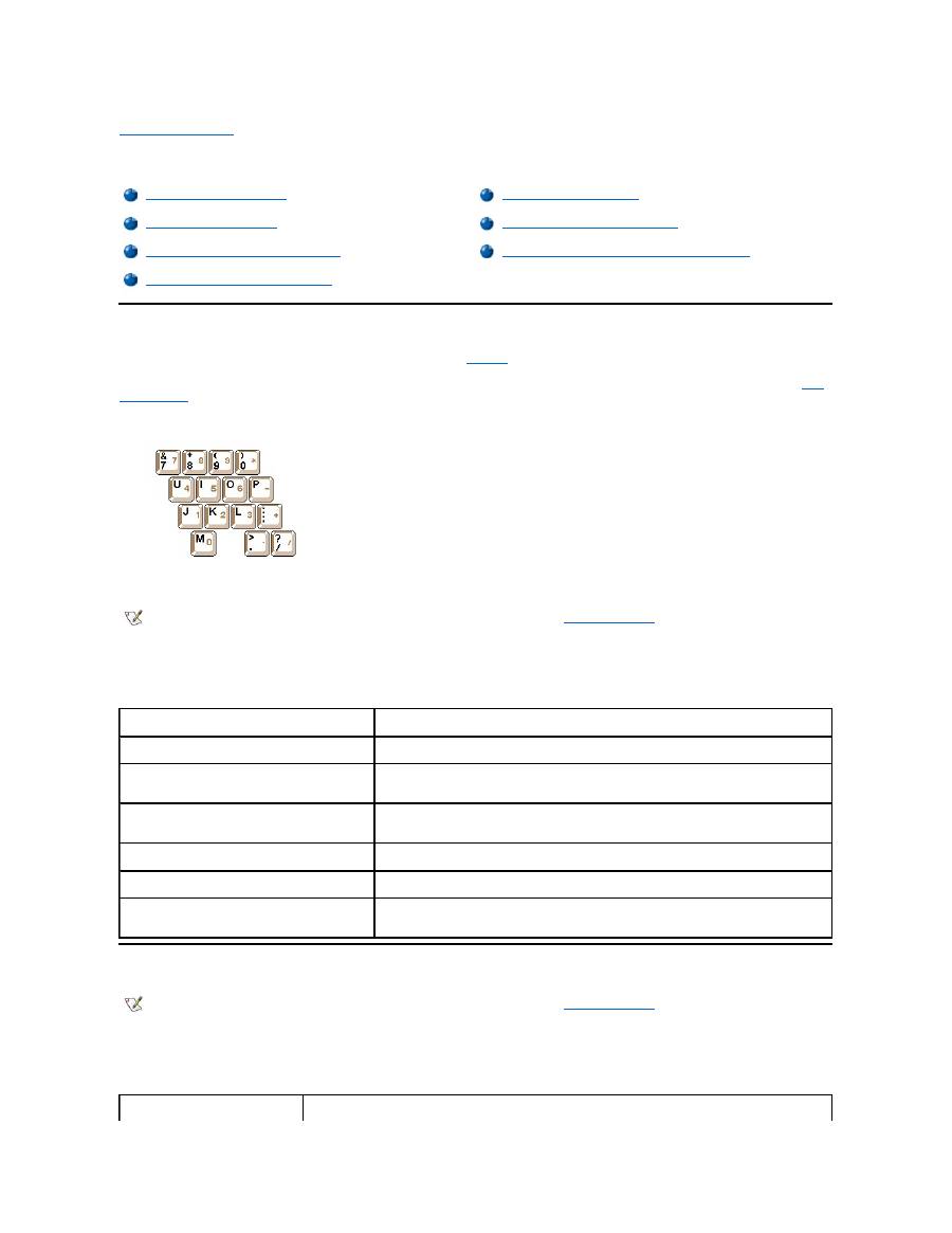
Back to Contents Page
Keyboard: Dell™ Latitude™ CS/CS x Portable Computers User's Guide
Embedded Numeric Keypad
As you work, you may want to use the embedded numeric keypad (see
Figure 1
) to enter numbers in spreadsheet or financial programs. The
embedded numeric keypad shares some of the keys on your computer's keyboard. On these keys, the number and symbol characters of the
numeric keypad appear in blue to the right of the main keypad characters. To activate the embedded numeric keypad, press <Num Lk> (the
Num
Lock indicator
lights up).
Figure 1. Embedded Numeric Keypad
Some key combinations can be used whether or not the keypad is activated.
Use the numeric keypad combinations in Table 1 to enable and disable several numeric keypad functions.
Table 1. Embedded Numeric Keypad Key Combinations
Display Key Combinations
Use the key combinations in Table 2 to adjust the computer's display.
Table 2. Display Key Combinations
Embedded Numeric Keypad
Speaker Key Combinations
Display Key Combinations
System Function Key Combinations
Power Conservation Key Combinations
CD-ROM and DVD-ROM Drive Key Combinations
Processing Speed Key Combinations
NOTE: On an external keyboard, use <Scroll Lock> with the appropriate keys if the
External Hot Key
option is enabled in the System
Setup program.
When Keypad Is On
Function
<Num Lk>
Toggles the embedded numeric keypad off
<Fn><
key
>
Temporarily disables the embedded numeric keypad; enables the
lowercase characters/functions of the keyboard
<Fn><Shift><
key
>
Temporarily disables the embedded numeric keypad; enables the
uppercase characters/functions of the keyboard
When Keypad Is Off
Function
<Num Lk>
Toggles the embedded numeric keypad on
<Fn><Shift><
number key
>
Temporarily enables a number or symbol key in the embedded
numeric keypad
NOTE: On an external keyboard, use <Scroll Lock> with the appropriate keys if the
External Hot Key
option is enabled in the System
Setup program.
Key Combinations
Function

* This key combination may not be supported by future operating systems.
Power Conservation Key Combinations
Use the key combinations in Table 3 to activate or turn off the computer's power conservation features.
Table 3. Power Conservation Key Combinations
* This key combination may not be supported by future operating systems.
Processing Speed Key Combinations
Use the key combinations in Table 4 to change the computer's processing speed.
Table 4. Processing Speed Key Combinations
<Fn> + down arrow
Incrementally decreases brightness.
<Fn> + up arrow
Incrementally increases brightness.
<Fn> + right arrow
Has no effect on your computer.
Decreases contrast on passive-matrix displays; has no effect on active-matrix
displays.
<Fn> + left arrow
Has no effect on your computer.
Increases contrast on passive-matrix displays; has no effect on active-matrix
displays.
<Fn><F5> *
Toggles the computer's display between regular video mode and reverse video mode
(white on black). This key combination works only if the computer is in text mode; it has no
effect if the computer is running a graphical operating system or application program.
<Fn><F7>
Toggles the computer
’
s display between expanded video mode and regular video mode.
<Fn><F8>
Switches the video image to the next display in the following sequence: the display, an
external monitor, or both displays simultaneously.
<Fn><d>*
Turns off the display.
NOTES: Contrast cannot be changed on an active-matrix (thin film transistor [TFT]) display, such as the display in your computer.
To use key combinations on an external keyboard, enable the
External Hot Key
option in the System Setup program and use <Scroll
Lock> instead of <Fn>.
NOTE: On an external keyboard, use <Scroll Lock> with the appropriate keys if the
External Hot Key
option is enabled in the System
Setup program.
Key Combinations
Function
<Fn><d>*
Turns off the display
<Fn><h>*
Turns off the hard-disk drive
<Fn><Esc>*
Activates suspend or standby mode
<Fn><a> or
<Fn><q> on French
keyboards
Activates suspend-to-disk mode
NOTE: On an external keyboard, use <Scroll Lock> with the appropriate keys if the
External Hot Key
option is enabled in the System
Setup program.
<Fn><\> *
Switches between the microprocessor's maximum speed and a slower
compatibility speed
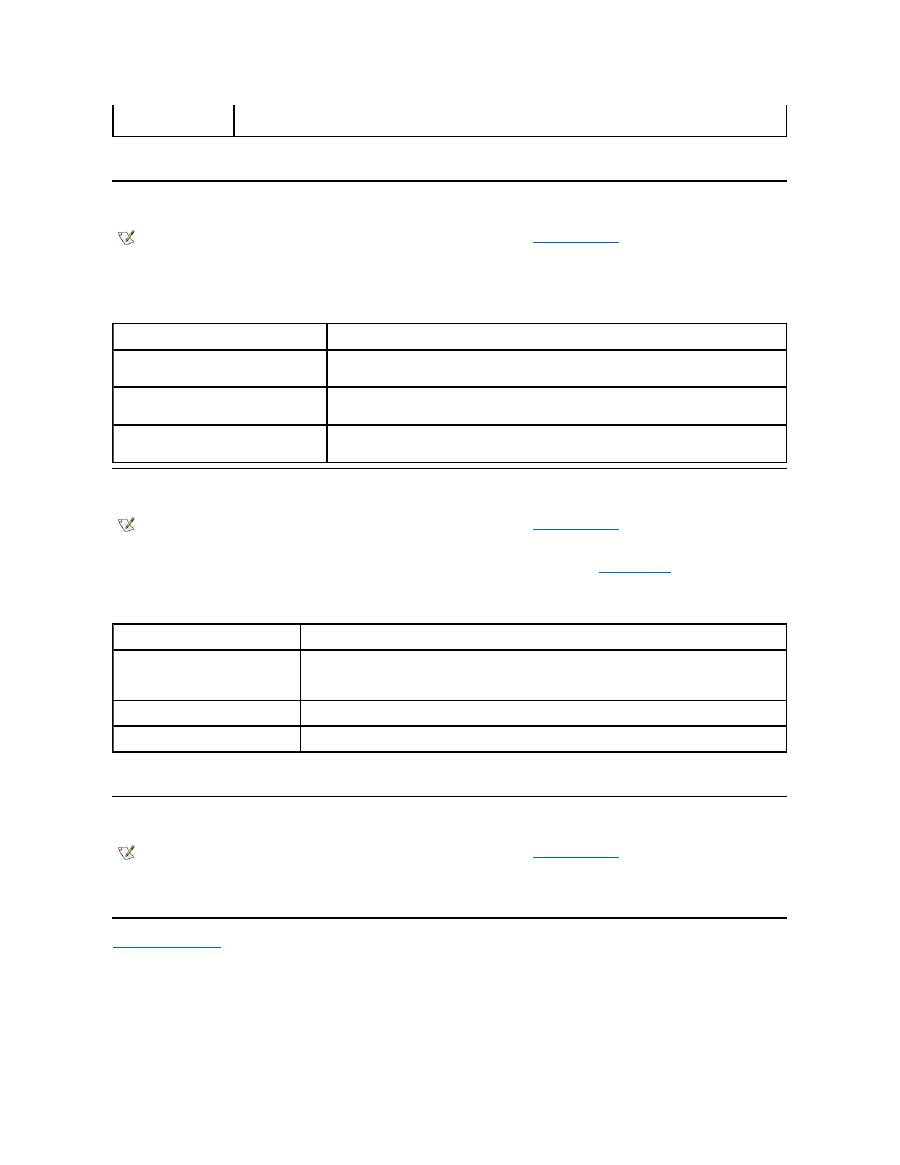
* This key combination may not be supported by future operating systems.
Speaker Key Combinations
Use the key combinations in Table 5 to adjust the computer's speaker volume and to enable and disable the speakers.
Table 5. Speaker Key Combinations
System Function Key Combinations
Use the key combinations in Table 6 to access MS-DOS, open the System Setup program, and open the
Battery Status
screen of the System
Setup program.
Table 6. System Function Key Combinations
* This key combination may not be supported by future operating systems.
CD-ROM and DVD-ROM Drive Key Combinations
To eject the CD-ROM or DVD-ROM tray, press <Fn><F10>.
Back to Contents Page
<Ctrl><\>
In full MS-DOS
®
mode or in a full-screen DOS box, switches between the
microprocessor
’
s maximum speed and a slower compatibility speed
NOTE: On an external keyboard, use <Scroll Lock> with the appropriate keys if the
External Hot Key
option is enabled in the System
Setup program.
Key Combinations
Function
<Fn><Page Up>
Increases the volume of the integrated speaker and the
external speakers, if attached
<Fn><Page Dn>
Decreases the volume of the integrated speaker and the
external speakers, if attached
<Fn><End>
Enables and disables the integrated speaker and the
external speakers, if attached
NOTE: On an external keyboard, use <Scroll Lock> with the appropriate keys if the
External Hot Key
option is enabled in the System
Setup program.
Key Combinations
Function
<Ctrl><Alt><Del>
Restarts (reboots) the computer in MS-DOS mode. In the Microsoft
®
Windows
®
95, Windows 98, and Windows NT
®
operating systems, click
the
Start
button and click
Shut Down
.
<Fn><F1>*
Opens the System Setup program.
<Fn><F3>*
Opens the
Battery Status
screen of the System Setup program.
NOTE: On an external keyboard, use <Scroll Lock> with the appropriate keys if the
External Hot Key
option is enabled in the System
Setup program.

Back to Contents Page
External Media Bay: Dell™ Latitude™ CS/CS x Portable Computers User's Guide
Using the External Media Bay
You can use the external media bay (see
Figure 1
) for the diskette drive that comes with your system. Alternatively, you can install an optional
device (such as a CD-ROM, DVD-ROM, SuperDisk LS-120, or second hard-disk drive) in the bay.
To install a device in the external media bay, perform the following steps:
1.
If your computer is running the Dell-installed Microsoft
®
Windows NT
®
operating system with Softex Docking Services, or if it is running
the Dell-installed Microsoft Windows
®
95 or Windows 98 operating system with Softex Bay Manager:
Right-click the Softex icon (the icon
looks like a tiny open portable computer) in the system tray at the bottom right on your display, and select either
Remove or Swap Devices
or
Insert Bay Devices
.
If your computer is not running one of the Softex programs: S
ave your work, close all open files and application programs, and turn off the
computer.
NOTICE: When a device is not inside the external media bay, it is fragile and must be handled carefully to avoid damage. Do not
press down on it or place a heavy object on top of it. Place the device in a travel case to keep it free of dust and liquids. Store the
device in a safe place.
2. If the external media bay contains a device, remove the media bay cable from the back of the bay. Then remove the device by sliding the
release latch on the bottom of the bay to the release position, holding it there, and pulling the device out of the bay.
3. Slide the new device firmly into the external media bay.
You should hear a click when the device is fully seated.
4. Connect the media bay cable.
Position the larger of the cable connectors with its shiny metal lip down, and connect it firmly to the back of the device through the slot in the
back of the bay. Make sure that the securing clips are fully engaged and the connector is fully seated. Make sure that the other end of the
cable is connected to the media bay connector on the right-hand side of the computer (see Figure 1).
Figure 1. External Media Bay
5.
If your computer is running Softex Docking Services or Softex Bay Manager: Click
OK
at the
Softex Docking Services
or
Softex Bay
Manager
screen. Click
OK
at the
Device Removal
screen (if it appears), and then click
OK
at the
Device Configured
screen.
If you turned off the computer in step 1: Press the power button to turn the computer back on.
Using the External Media Bay
Setting Up a Second Hard-Disk Drive
NOTE: If desired, you can use the media bay cable to connect a device directly to the external media bay connector, without using the
external media bay.
NOTE: For the latest information on Softex Docking Services software, see
http://www.dell.com/products/notebook/latitude/NT40.htm
.

Setting Up a Second Hard-Disk Drive
The first time you install a second hard-disk drive in the external media bay, you must format that drive. For instructions, see the documentation that
came with the device.
Back to Contents Page

Back to Contents Page
Media Options: Dell™ Latitude™ CS/CS x Portable Computers User's Guide
Back to Contents Page
External Media Bay
CD-ROM and DVD-ROM Drives
Diskette Drive

Back to Contents Page
PC Cards: Dell™ Latitude™ CS/CS x Portable Computers User's Guide
About PC Cards
The computer provides two slots in which you can install PC Cards that comply with Release 2.01 of the Personal Computer Memory Card
International Association (PCMCIA) standard and Release 4.2 of the Japanese Electronic Industry Development Association (JEIDA) standard.
The computer supports type I, type II, and type III PC Cards, such as modems, local area network (LAN) cards, wireless LAN cards, and small
computer system interface (SCSI) cards. Also supported are such memory devices as static random-access memory (SRAM) cards that emulate
diskettes, random
-access memory (RAM) cards, and one-time programmable (OTP) ROM cards, and advanced technology attachment (ATA)
cards that emulate integrated drive electronics (IDE) hard-disk drives.
If you are using the Microsoft
®
Windows
®
95 or Windows 98 operating system, you can use a zoomed video (ZV) PC Card, such as a hardware
Moving Picture Experts Group (MPEG) decoder. ZV cards must be used only in the upper PC Card slot. (The Microsoft Windows NT
®
4.0
operating system does not support ZV.)
NOTICE: Take extra precautions if you use extended PC Cards in your computer. Extended cards are longer versions of standard
PC Cards. They fit into, and operate correctly with, your computer. However, they extend beyond the edge of the computer when
installed. If something strikes the exposed end of an installed card, your system board can be damaged. Because of space
considerations, you may have trouble using two PC Cards in your computer if one of them is an extended card. It may be easier to
use an extended card if you install it in the upper PC Card slot. Always remove an extended PC Card before you pack the computer
in its carrying case.
You can use the following PC Card combinations in the PC Card slots:
l
A single type I or type II card (using either the upper or lower PC Card slot)
l
A single type III card (using the lower
PC Card slot only)
l
One type I card and one type II card (using either slot)
l
Two type I cards or two type II cards
Installing PC Cards
PC Cards are generally marked with a symbol, such as a triangle or an arrow, to indicate which end should be inserted into the slot. The cards are
keyed to prevent incorrect insertion. If card orientation is not clear, see the documentation that came with the card.
You do not need to turn off your computer or exit suspend or standby mode before you install a PC Card. To install a PC Card (see Figure 1),
perform the following steps.
Figure 1. Installing a PC Card
About PC Cards
Removing PC Cards
Installing PC Cards
Configuring PC Cards
NOTES: A PC Card is not a boot device.
The "type" of a card refers to its thickness, not its functionality.
Your computer recognizes most I/O cards and automatically loads the device driver associated with that card.
Note: Use a ZV PC Card in the upper slot only.
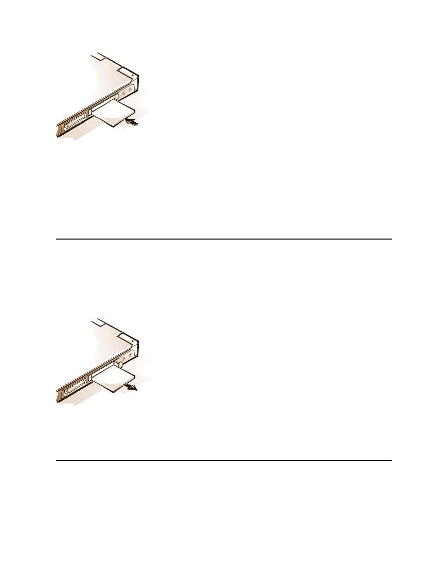
1.
If necessary, remove the blank from the PC Card slot you intend to use. Press the eject button once to pop the button out, press it again to
eject the blank partway, and then pull the blank out.
2.
Make sure that the eject button is pressed all the way in. Hold the card with its orientation symbol pointing into the slot and the top side of the
card facing up.
3.
Insert the card into the slot and press in firmly until the card is completely seated in the internal PC Card connector.
4.
If you encounter too much resistance when inserting it, do not force the card. Check the card's orientation and try again.
PC Card Blanks
Save the blank to use whenever you do not have a PC Card installed. The blank protects the PC Card slot from dust and other particles.
Removing PC Cards
NOTICE: If you are using Windows 95 or Windows 98, use the PC Card configuration utility on the taskbar to select and stop a card
before you remove it. If you do not remove the card in the configuration utility, you could lose data from open application programs.
To remove a PC Card (see Figure 2), perform the following steps.
Figure 2. Removing a PC Card
1.
Press the PC Card eject button once to pop the button out, and then press the button in again to eject the card partway. (The button may or
may not pop out again when you eject the card.)
2.
Gently remove the card.
To protect the PC Card slots, install a blank if you are not going to use the slots.
Configuring PC Cards
The PC Card configuration utility performs the following functions:
l
Notifies you whenever a PC Card is inserted and tells you how the card is configured
l
Automatically loads the proper device driver if it is available on the hard-disk drive
l
If drivers are not available on the hard-disk drive, prompts you to install them by using the device driver diskette that came with the card

The operating system automatically detects a PC Card and opens the
Add New Hardware
menu from the
Control Panel
. For information, see
the PC Card operating system documentation.
Back to Contents Page

Back to Contents Page
Powering Your Computer: Dell™ Latitude™ CS/CS x Portable Computers User's Guide
Back to Contents Page
AC Adapter
Power Management Settings
Batteries

Back to Contents Page
Preface: Dell™ Latitude™ CS/CS x Portable Computers User's Guide
About This Guide
This guide is intended for anyone who uses the Dell Latitude CS/CS
x
portable computers. It can be used by both first-time and experienced
computer users who want to learn about the features of the computer. This guide also provides basic troubleshooting procedures and instructions
for using the Dell Diagnostics to test your computer and its components. The sections are summarized as follows:
l
"
Introduction
"
—
overview of the computer features and available upgrades
l
"
Setup and Operation
"
—
instructions on operating your computer
l
"
Powering Your Computer
"
—
instructions and options on how to power your computer
l
"
Traveling With Your Computer
"
—
suggestions on how to travel safely with your computer
l
"
Drivers
"
—
instructions on how to install driver software on your computer
l
"
Customizing Your Computer
"
—
instructions on accessing the System Setup program, power management software, and the Suspend-to-
Disk utility, all of which allow you to change system settings affecting your computer's power conservation features
l
"
Removing and Replacing Parts
"
—
instructions on how to remove and install hard-disk drives and memory modules
l
"
Troubleshooting Your Computer
"
—
initial checks and procedures that can be used to solve basic computer problems, general guidelines
on analyzing software problems, messages, and beep codes
l
"
Technical Specifications
"
—
reference material about the details of your computer
l
"
Getting Help
"
—
help tools Dell provides to assist you if you have a problem with the computer and explains how and when to call Dell for
technical assistance.
Warranty and Return Policy Information
Dell Computer Corporation ("Dell") manufactures its hardware products from parts and components that are new or equivalent to new in
accordance with industry-standard practices.
For information about the Dell warranty and return policy, see your Dell Latitude
System Information
guide.
Other Documents You May Need
Besides this
User's Guide
, the following documentation is included with your computer.
l
The operating system
Setup Guide
, which describes how to set up the Dell-installed operating system on your computer.
l
Microsoft
®
Windows 95
®
, Windows 98, and Windows NT
®
operating system documentation is included if you ordered your operating
system from Dell. This documentation describes how to configure and use your operating system software.
l
Documentation is included with any options you purchase separately from your computer. This documentation includes information that you
need to configure and install these options in your Dell computer.
l
"Readme" files may be installed on your hard-disk drive to provide last-minute updates about technical changes to your computer or
advanced technical reference material intended for experienced users or technicians.
About This Guide
Notational Conventions
Warranty and Return Policy Information
Typographical Conventions
Other Documents You May Need
NOTE: Documentation updates are sometimes included with your computer to describe changes to your computer or software. Always
read these updates
before
consulting any other documentation because the updates contain the latest information.

Notational Conventions
The following subsections list notational conventions used in this document.
Notes, Notices, and Cautions
Throughout this guide, blocks of text may be accompanied by an icon and printed in bold type or in italic type. These blocks are notes, cautions,
and warnings, and they are used as follows:
Typographical Conventions
The following list defines (where appropriate) and illustrates typographical conventions used as visual cues for specific elements of text throughout
this document:
l
Interface components
are window titles, button and icon names, menu names and selections, and other options that appear on the monitor
screen or display. They are presented in bold.
Example: Click
OK
.
l
Keycaps
, the labeling that appears on the keys on a keyboard, are enclosed in angle brackets.
Example: <Enter>
l
Key combinations
are series of keys to be pressed simultaneously (unless otherwise indicated) to perform a single function.
Example: <Ctrl><Alt><Enter>
l
Commands
presented in lowercase bold are for reference purposes only and are not intended to be typed at that particular point in the
discussion.
Example: "Use the
setup
command to . . . ."
In contrast, commands presented in the Courier New font are intended to be typed as part of an instruction.
Example: "Type
format a:
to format the diskette in drive A."
l
Filenames
and
directory names
are presented in lowercase bold.
Examples:
autoexec.bat
and
c:\windows
l
Syntax lines
consist of a command and all its possible parameters. Commands are displayed in lowercase bold; variable parameters
(those for which you substitute a value) are displayed in lowercase italics; constant parameters are displayed in lowercase bold. The
brackets indicate items that are optional.
Example:
del
[
drive
:
] [[
path
]
filename
] [
/p
]
l
Command lines
consist of a command and may include one or more of the command's possible parameters. Command lines are
presented in the Courier New font.
Example:
del c:\myfile.doc
l
Screen text
is text that appears on the screen of your display or external monitor. It can be a system message, for example, or it can be text
that you are instructed to type as part of a command (referred to as a
command line)
. Screen text is presented in the Courier New font.
Example: The following message appears on your screen:
No boot device available
l
Variables
are symbols for which you substitute a value. They are presented in italics.
Example: module
n
(where
n
represents the memory module number)
Back to Contents Page
NOTE: A NOTE indicates important information that helps you make better use of your computer.
NOTICE: A NOTICE indicates either
potential damage to hardware or loss of data and tells you how to avoid the problem.
CAUTION: A CAUTION indicates the potential for bodily harm and tells you how to avoid the problem.
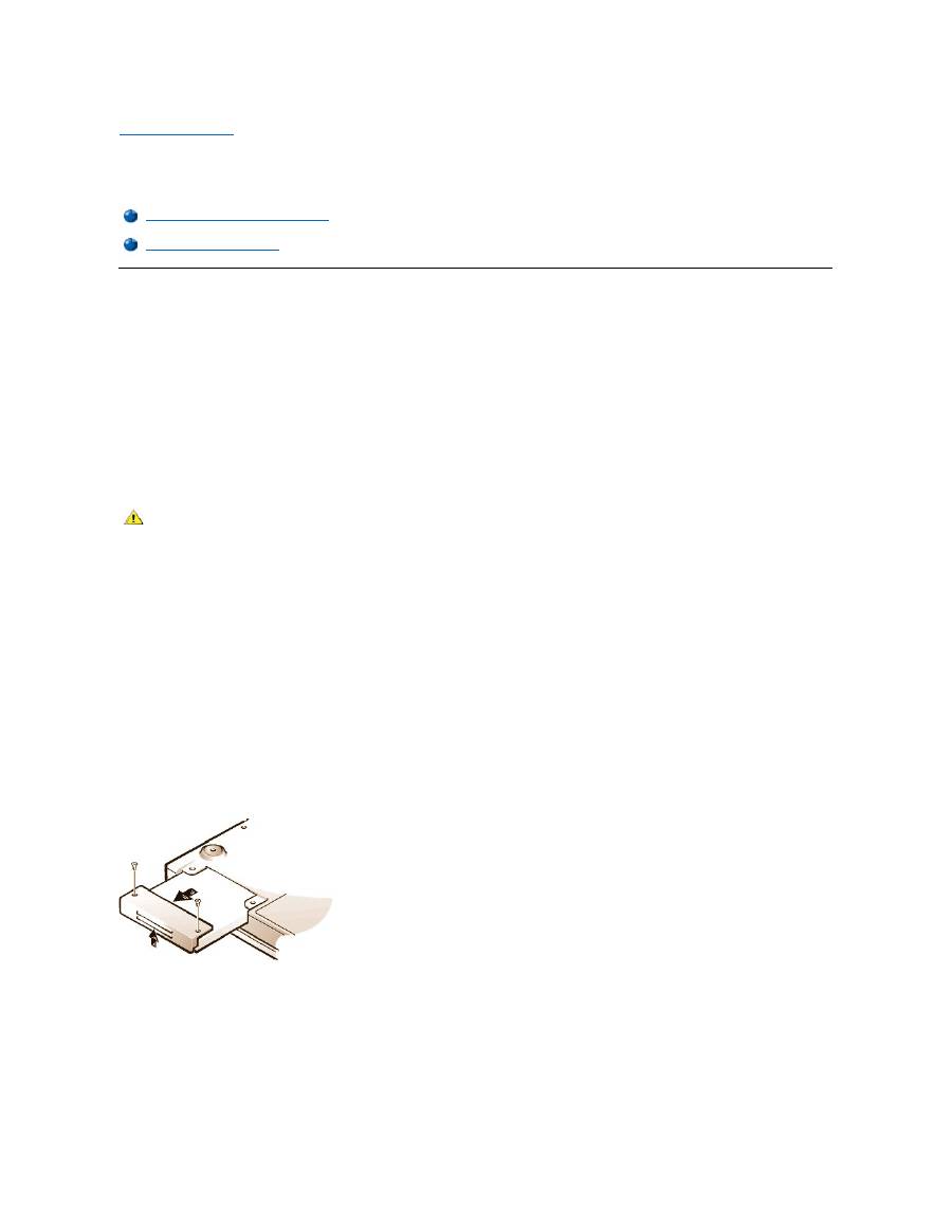
Back to Contents Page
Removing and Replacing Parts: Dell™ Latitude™ CS/CS x Portable Computers User's Guide
Replacing a Primary Hard-Disk Drive
NOTICE: To prevent data loss, turn off your computer before you remove the hard-disk drive. Do not remove the hard-disk drive if
the computer is in suspend (or standby) mode or if the drive access indicator is lit. Removing the drive under these conditions will
lead to loss of data.
NOTICE: Hard-
disk drives are extremely fragile and must be handled carefully to avoid damage. Follow these guidelines:
l
The primary hard-disk drive is installed in a metal carrier to protect the drive and make installation easier. When you remove and
install hard-disk drives, handle the drive carrier, not the drive itself.
l
Never press down on the top of the drive.
l
Do not drop the drive. Even a slight jar or bump can damage the drive heads and spinning plates, thus rendering the drive
inoperable.
To replace a primary hard-disk drive, perform the following steps:
1.
Save any open files, turn off the computer, and remove any installed batteries.
NOTICE: To avoid scratching the top of the computer, make sure that your work surface is clean. You may want to put down a
protective mat before turning over the computer.
2.
Remove the old hard-disk drive from the drive bay.
Close the display and turn the computer over. Using a #0 (very small) Phillips-
head screwdriver, remove the two screws in the hard
-
disk drive door (see Figure 1). Save the screws for use later in this procedure.
With the computer still upside-down, press upward on the hard-disk drive door until it feels loose; then grasp the door and pull it and the
drive straight out from the side of the computer.
When the hard-disk drive is not in the computer, protect the drive from exposure to static electricity.
Figure 1. Removing a Hard-Disk Drive
3.
Remove the new hard-disk drive assembly from its packaging.
Save the original packaging to use when you store or ship the hard-disk drive.
NOTICE: If the hard-disk drive assembly does not slide in easily, pull it out and try again. To avoid damage, do not force the drive
assembly into the bay.
4.
Install the new hard-disk drive in the computer.
Insert the drive, connector first and label facing down, into the drive bay. Holding the drive door up slightly, push the drive all the way into the
Replacing a Primary Hard-Disk Drive
Installing a Memory Module
CAUTION: The primary hard-disk drive may be hot to the touch under extreme environmental conditions. If the drive is hot,
allow it to cool before you replace it.

bay. Then press down and in on the drive door until it snaps into position, flush with the computer case.
5.
Replace the screws you removed in step 2. Be careful not to overtighten the screws.
If you have installed a new hard-disk drive, follow the directions that came with the drive to partition and logically format the drive and to create an
S2D partition.
Preparing a New Primary Drive
Every primary hard-disk drive must be physically formatted, partitioned, and logically formatted before it can be used to store data. Every primary
hard-disk drive from Dell is physically formatted before it is sent to you. Use the program(s) provided by your operating system to partition and
logically format the hard-disk drive.
For more information, see both your operating system and your drive documentation
.
Installing Memory Modules
Your system's factory-installed memory can range from 64 megabytes (MB) to a system maximum of 320 MB. Depending on the memory already
installed, you may be able to increase memory by installing a 32-, 64-, or 128-MB synchronous dynamic random-access memory (SDRAM) small-
outline dual-inline memory modules (SODIMMs) in the memory upgrade socket. The maximum achievable memory for your system depends on the
system's original memory configuration.
NOTICE: Dell Latitude CS/CS
x
portable computers support only SDRAM SODIMMs. Extended-data out (EDO) memory modules are
not supported.
To upgrade computer memory, you can install or replace a memory module through the memory module cover on the underside of the
computer.
To prepare the computer for the removal or installation of a memory module, perform the following steps.
NOTICE: Ground yourself by touching an unpainted metal surface of a connector on the back of the computer. While you work,
periodically touch the connector to dissipate any static electricity that might harm internal components.
1.
Turn off the computer and any attached devices.
Do not install memory modules while the computer is in suspend, standby, or suspend-to-disk mode.
2.
If the computer is docked, undock it.
3.
Disconnect the computer and peripherals from their electrical outlets to reduce the potential for personal injury or shock.
4.
Disconnect any telephone or telecommunication lines from the computer.
5.
Remove the battery from the battery bay.
To remove or install a memory module, perform the following steps.
NOTICE: To avoid scratching the top of the computer, make sure that your work surface is clean. You may want to put down a
protective mat before turning over the computer.
1.
Close the display, turn the computer upside down, and remove the memory module cover (see Figure 2).
Use a #1 Phillips-head screwdriver to remove the two screws securing the memory module cover. When the memory module cover pops up
slightly, lift it up and remove it to expose the memory socket or installed memory module beneath.
Figure 2. Removing the Memory Module Cover
2.
If you are replacing a memory module, remove the old one.
Carefully spread apart the inner metal tabs of the memory module socket just far enough for the memory module to disengage from the
socket (it should pop up slightly). Then lift the memory module away from the socket (see Figure 3).
Figure 3. Removing a Memory Module
NOTE:
If necessary, print these instructions for reference before proceeding.
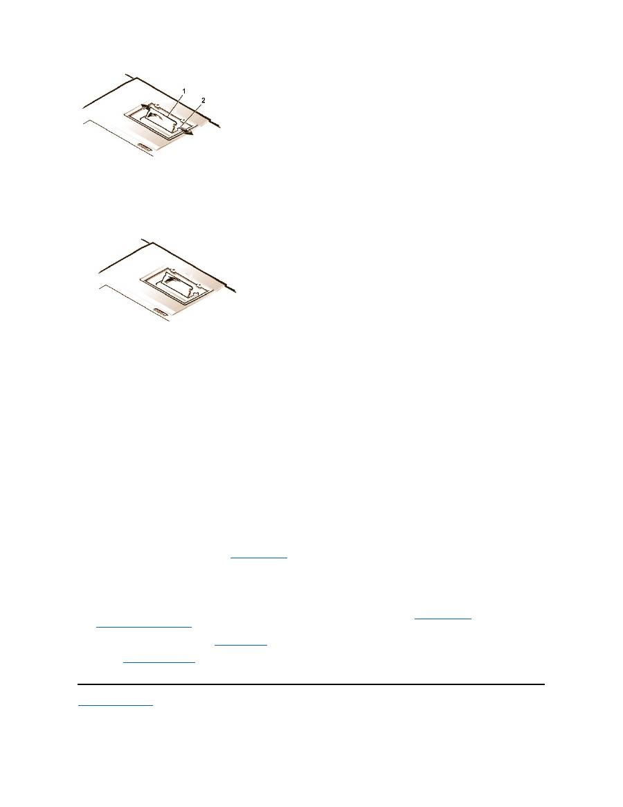
3.
Ground yourself and unpack the new memory module from the upgrade kit.
4.
Install the new memory module in the socket (see Figure 4).
Figure 4. Installing a Memory Module
Memory modules are
keyed
, or designed to fit into their sockets in only one direction. The socket is notched so that the memory module can
be seated only one way as follows:
a.
Align the memory module
’
s edge connector with the slot in the center of the memory module socket.
b.
With the module at a 45-degree angle, press the memory module
’
s edge connector firmly into the memory module socket.
c.
Pivot the memory module down until it clicks into place.
If you do not hear a click as each end of the memory module snaps into the metal tabs, remove the memory module and reinstall it.
5.
Replace the memory module cover as follows:
a.
Set the memory module cover into the opening, aligning the tabs on one side with the slots in the computer cover.
b.
Press the cover down and replace the screws you removed in step 1.
NOTICE: After installation, if the memory module cover does not fit or is difficult to close, you may have installed the memory module
improperly. Remove the module and reinstall it. Do not force the memory module cover to close because you may damage your
computer.
6.
Reconnect your computer and devices to their electrical outlets and turn them on.
As the computer boots, it detects the presence of additional memory and automatically updates the system configuration information.
7.
In one of the following ways, verify that the
System Memory
option in the System Setup program reflects the newly installed memory:
l
Click the
Start
button, point to
Settings
, click
Control Panel
, and click the
System
icon. The amount of memory installed in the
computer is displayed in the lower-right corner of the
General
tab window.
l
In the System Setup program, the
System Memory
option appears in the lower-right corner of pages 1, 2, and 4.
If the system memory total is incorrect, the memory module(s) may not be installed properly. Repeat
preparatory steps
1 through 5 and
removal and installation steps
1 through 7 until the memory total is correct.
8.
Run the
System Memory
test of the
Dell Diagnostics
to confirm that all installed memory modules are operating correctly.
9.
Use the
Suspend-to-Disk utility
to update the S2D partition on your hard-disk drive. The S2D partition stores system data while the computer
is in S2D mode.
Back to Contents Page
1
Memory module
2
Metal tabs (2)

Back to Contents Page
Suspend-to-Disk Utility: Dell™ Latitude™ CS/CS x Portable Computers User's Guide
Suspend-to-Disk Utility
The Suspend-to-Disk (S2D) utility allows you to manage the S2D partition in your file system as your computing needs change. For instance, you
can remove the S2D partition if you need the space on the hard-disk drive for other purposes, or you can use the S2D utility to create the partition
if you have removed it.
Removing the S2D Partition
If you want to use the S2D partition on your hard-disk drive for another purpose (for instance, if you are running out of file space), perform the
following steps to remove the partition:
1. At an MS-DOS
®
prompt, type
cd c:\dell\util
and press <Enter> to change to the directory on your hard-disk drive that contains the
S2D utility files.
If you are using an operating system that is not compatible with MS-DOS, see the
readme.s2d
file for instructions.
2. Type
rms2d
and press <Enter>.
Status messages appear on the display as the removal process progresses. When the S2D partition has been removed, the following
message appears:
The S2D partition was successfully removed.
Creating the S2D Partition
The
mks2d.exe
file creates the S2D partition the computer uses to store the system data that is saved when you put the computer in S2D mode.
Use the
mks2d.exe
file to create a new S2D partition in the following cases:
l
If Dell did not install MS-DOS on your hard-disk drive
l
If you increase the amount of system memory by adding a memory module
l
If you used the
rms2d.exe
file to remove the original S2D partition and now want to recreate the partition
l
If your hard-disk drive becomes corrupted
l
If you install a new hard-disk drive
l
If you received the system utilities separately on diskette or if you deleted the S2D utility from your hard-disk drive
To create an S2D partition, perform the following steps.
1. At an MS-DOS prompt, type
cd c:\dell\util
and press <Enter> to change to the directory on your hard-disk drive that contains the
S2D utility files.
2. Type
mks2d
and press <Enter>.
As the utility builds the partition, status messages appear on the display. If an error message appears, it provides information about
which steps to take to continue building the partition.
When the S2D partition has been built and verified, the following message appears:
Suspend-to-Disk Utility
Removing the S2D Partition
Creating the S2D Partition
NOTE: After you remove the S2D partition, the computer cannot enter S2D mode until you recreate the partition. If you try to enter S2D
mode and receive the message
No Suspend-To-Disk partition available
, you must create an S2D partition.
NOTE: If you are creating the partition on a new hard-disk drive, if Dell did not install MS-DOS on your hard-disk drive, or if you are
using an operating system that is not compatible with MS-DOS, read the
readme.s2d
file before performing the following procedure.

The S2D partition was successfully created.
Back to Contents Page

Back to Contents Page
Securing Your Computer: Dell™ Latitude™ CS/CS x Portable Computers User's Guide
About Passwords
A primary password prevents unauthorized access to the computer at start-up. An administrator password can be used in place of the primary
password. A hard-disk drive password helps prevent the unauthorized access of data on the hard-disk drive, even when the device is placed into
another computer.
NOTICE: The password features provide a high level of security for the data in your computer or hard-disk drive. However, they are
not foolproof. If your data requires more security, you should obtain and use additional forms of protection, such as data encryption
programs or PC Cards with encryption features.
If you forget any of your passwords,
call Dell
. For your protection, Dell
’
s technical support staff will ask you for proof of your identity to make sure
that an unauthorized person is not trying to use the computer.
Using a Primary Password
The primary password allows you to protect the computer from unauthorized access.
After assigning a primary password, you must enter it each time you turn on your computer. The following message appears at the bottom of the
screen each time you turn on the computer:
Please type in the primary or administrator password and press <Enter>.
To continue, type your password and press <Enter>.
If you have assigned an administrator password, you can use it instead of the primary password. The computer does not specifically prompt you
for the administrator password.
NOTICE: If you disable the administrator password, the primary password is also disabled.
Using an Administrator Password
The administrator password is designed to give system administrators or service technicians in large companies access to computers for repair
or reconfiguration. The administrators or technicians can assign identical administrator passwords to groups of computers as they are unpacked
and configured, leaving the primary password free to be assigned by the user.
When you set an administrator password, the
Configure Setup
option becomes available in the System Setup program. The
Configure Setup
option allows you to restrict access to the System Setup program in the same way a system password restricts access to the system.
The administrator password can be used in place of the primary password. Whenever you are prompted to enter the primary password, you can
enter the administrator password instead.
If you forget the primary password and do not have an administrator password assigned, or if you have both a primary and an administrator
password assigned but forget them both,
call Dell
.
NOTICE: If you disable the administrator password, the primary password is also disabled.
About Passwords
Using a Hard-Disk Drive Password
Using a Primary Password
Physically Securing the Computer
Using an Administrator Password
Asset Tag Utility
NOTES: All three passwords are disabled when you receive your computer. You need to assign those passwords if you require
password security for your computer. Some companies may assign any or all of these passwords before distributing the computer.
Use the
System Setup program
to assign all passwords.
NOTE: If no password is entered within 2 minutes, the computer returns to its previous state.
NOTE: The administrator password provides access to the system, but it does not provide access to the hard-disk drive when it is
protected by a password.

Using a Hard-Disk Drive Password
The hard-disk drive password helps protect the data on your hard-disk drive from unauthorized access. You can also assign a password for the
modular hard-disk drive (if one is being used) that can be the same as or different from the password for the primary hard-disk drive.
After assigning a hard-disk drive password, you must enter it each time you turn on the computer and each time you resume normal operation from
suspend mode or standby mode.
If the hard-disk drive password is enabled, the following message appears at the bottom of the screen each time you turn on the computer:
Please type in the hard-disk drive password and press <Enter>.
To continue, enter the hard-disk drive password. Press <Esc> to return the computer to its previous state
—
suspend, standby, or off.
If you enter the wrong password, the following message appears:
Invalid password
[Press Enter to retry]
If the correct password is not entered in three attempts, you receive a message stating that the hard-disk drive cannot be found. If the hard-disk
drive is inaccessible and the
boot options
in the System Setup program are set to allow booting from another device, the computer tries to boot
from another device. If all boot attempts are unsuccessful, the computer prompts you to enter the System Setup program and modify the boot
options.
Physically Securing the Computer
To prevent unauthorized removal of the computer, you can use a security cable to attach the computer to an immovable object. Your computer has
a security cable slot located on the left side of the computer near the back (
see Figure 1
).
Description of Security Cable Slots
The security cable slot allows you to attach a commercially available antitheft device to the computer. Antitheft devices for portable computers
usually include a segment of metal-stranded cable with an attached locking device and associated key. You can use a security cable on your
computer when it is undocked and also when it is docked in a Dell Latitude C/Port Family Advanced Port Replicator (C/Port APR) or a C/Dock
Family Expansion Station.
Basic Instructions for Using Security Cable Slots
To prevent unauthorized removal of your computer, loop the cable around an immovable object, insert the locking device into either of the security
cable slots, and lock the device. See Figure 1 for an example of how to secure your computer. Complete instructions for installing this kind of
antitheft device are usually included with the device.
Figure 1. Securing the Computer
NOTE: Hard-disk drives that are not purchased from Dell for use with Latitude C-Family computers may not support the hard-disk drive
password option.
NOTE: If no password is entered within 2 minutes, the computer returns to its previous state.
NOTES: If the hard-disk drive password, the modular hard-disk drive password, and the primary password are the same, you are
prompted only for the primary password. If the hard-disk drive password is different from the primary password, you are prompted for
both. Two different passwords provide greater security.
The administrator password provides access to the system, but it does not provide access to the hard-disk drive when it is protected by a
password.
NOTE: Antitheft devices are of differing designs. Before purchasing such a device, make sure that it will work with the security cable slot
in your computer.

Asset Tag Utility
Dell has installed the Asset Tag utility on your computer. The Asset Tag utility allows you to perform the following actions:
l
View the computer's service tag
The non-modifiable service tag, which is viewable in the System Setup program, is set by Dell at the factory. It is used to identify your
computer to Dell for service and warranty purposes.
l
Set, view, and modify the computer's asset tag
The asset tag, which can be set by you or your company, is optional and is not required or used by Dell. The asset tag can be used in any
way desired; typically it is used by a company to differentiate and identify multiple computers that use an internally assigned identifier.
l
Set, view and modify the computer's owner tag
The owner tag, which can be set by you or your company, is optional and is not required or used by Dell. It can be used in any way desired.
Typically, it is used by a company to identify the computer as belonging to the company; it might contain a telephone number that can be
used to help return a unit to its owner. This tag is displayed on the system log-on screen and on the screens that prompt for the primary and
hard-disk drive passwords.
Viewing Existing Asset, Service, and Owner Tags
To view existing asset, service, and owner tags, perform the following steps:
1. Click the
Start
button, point to
Programs
, and click
MS-DOS Prompt
.
2. Type
cd c:\Dell\Util
and press <Enter>.
3. Type
asset
and press <Enter>.
Assigning an Asset Tag
An asset tag can have up to ten characters; any combination of characters is valid except those that begin with a forward slash (/) or a question
mark (?). Spaces count as characters. To assign or change an asset tag, perform the following steps:
1.
Click the
Start
button, point to
Programs
, and click
MS-DOS Prompt
.
2.
Type
cd c:\Dell\Util
and press <Enter>.
3. Type
asset
and a space followed by the new tag, and press <Enter>.
For example, type the following command line and press <Enter>:
asset 1234 $AB&C
4.
When the computer prompts you to verify that you want to change the asset tag, type
y
and press <Enter>.
The computer displays the new or modified asset tag and the service tag.
Deleting an Asset Tag
To delete the asset tag without assigning a new one, perform the following steps:
1.
Click the
Start
button, point to
Programs
, and click
MS-DOS Prompt
.
2.
Type
cd c:\Dell\Util
and press <Enter>.
3.
Type
asset /d
and press <Enter>.
Assigning an Owner Tag
An owner tag can have up to 48 characters, including spaces. Any combination of characters is valid except those that begin with a forward slash
(/) or a question mark (?). To assign an owner tag, perform the following steps:
1.
Click the
Start
button, point to
Programs
, and click
MS-DOS Prompt
.
2.
Type
cd c:\Dell\Util
and press <Enter>.
3.
Type
asset /o
and a space followed by the new owner tag, and press <Enter>.
For example, type the following command line and press <Enter>:
NOTE: For security reasons, you cannot set, change, or delete the asset tag if either the primary or the administrator password is set.
asset /o ABC Company
4.
When the computer prompts you to verify that you want to change the owner tag, type
y
and press <Enter>.
The computer displays the new owner tag.
Deleting an Owner Tag
To delete the owner tag without assigning a new one, perform the following steps:
1.
Click the
Start
button, point to
Programs
, and click
MS-DOS Prompt
.
2.
Type
cd c:\Dell\Util
and press <Enter>.
3.
Type
asset /o /d
and press <Enter>.
Table 1
lists the command-line options you can use with the Asset Tag utility. To use one of these options, open an MS-DOS
®
prompt, type
asset
and a space followed by the option, and then press <Enter>.
Table 1. Asset Tag Utility Commands
Back to Contents Page
NOTE: For security reasons, you cannot set, change, or delete the owner tag if either the primary or the administrator password is set.
Asset Tag
Command
Function
asset
Displays the asset, service, and owner tags
asset <
tag
>
Sets a new asset tag
asset /d
Deletes the asset tag
asset /o
<tag>
Sets a new owner tag
asset /o /d
Deletes the owner tag
asset /?
Displays the
Asset Tag
utility help screen

Back to Contents Page
Using the System Setup Program : Dell™ Latitude™ CS/CS x Portable Computers User's Guide
Overview
Each time you turn on your computer, it compares the installed hardware with the system configuration information stored in nonvolatile random-
access memory (NVRAM). If the system detects a discrepancy, it generates an error message for each incorrect configuration setting. You can
use the System Setup program to adjust the configuration settings.
You can use the System Setup program as follows:
l
To set or change user-selectable features
—
for example, your password or power management features
l
To verify information about your computer's current configuration, such as the amount of system memory
For some setup options, you must reboot the computer before any changes take effect. Changes for other options take effect immediately.
After you set up your computer, run the System Setup program to familiarize yourself with your system configuration information and optional
settings. Dell recommends that you write down the information for future reference.
For more information, see "
System Setup Options
."
Entering the System Setup Program
To enter the System Setup program, press <Fn><F1> at any time on the computer keyboard (or press <Scroll Lock><F1> on an external keyboard
if the
External Hot Key
option is enabled). To open the System Setup program directly to the
Battery Status
screen, press <Fn><F3> on the
computer keyboard (or press <Scroll Lock><F3> on an external keyboard if the
External Hot Key
option is enabled).
To exit the System Setup program, press <Esc>. If you change the setting of an option that requires rebooting to take effect, exit the operating
system
before
rebooting. (The
Help
text in the upper-right corner of System Setup screens 1, 2, and 4 tells you if the computer must be rebooted.)
For more information, see "
System Setup Options
."
Using the System Setup Program
The System Setup screens display the current setup and configuration information and optional settings for your computer. Information on the
screens is organized in five boxed areas:
l
Title
The box at the top of all screens lists the page number, system name, and version number of the basic input/output system (BIOS).
l
Options
The box on the left half of screens 1, 2, and 4 lists options that define the installed hardware in your computer and the power conservation
Overview
Entering the System Setup Program
Using the System Setup Program
NOTE:
If you change an option that is activated by rebooting, the System Setup program displays the setting you selected rather than
the setting currently in effect. You
must
reboot for the new setting to take effect.
NOTES: If the computer uses the Microsoft
®
Windows
®
95 operating system, you can also use the Dell Control Center to view and
change the system configuration. Access the Dell Control Center from the
Dell Accessories
folder.
If the computer uses the Microsoft Windows NT
®
4.0 or Windows 98 operating system, you must use the System Setup program to view
and change your system configuration.
NOTE: If the System Setup program is running when the computer enters suspend mode, the computer exits the System Setup
program and then enters suspend mode.

and security features for your computer.
Fields next to the options contain settings or values. You can change those values that appear white on the screen. Options or values that you
cannot change (because they are determined or calculated by the computer) appear dimmed or blue, depending on your display.
l
Help
The box on the upper-right half of screens 1, 2, and 4 displays help information for the option with a currently highlighted field.
l
Computer data
The box in the lower-right corner of screens 1, 2, and 4 displays information about your computer.
l
Key functions
The line of boxes across the bottom of all screens lists keys and their functions within the System Setup program.
For more information, see "
System Setup Options
."
Back to Contents Page
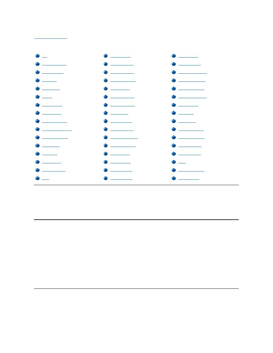
Back to Contents Page
System Setup Options: Dell™ Latitude™ CS/CS x Portable Computers User's Guide
AC
AC
, an option under
Power Management
, allows you to set different time-outs for the following options when you operate your computer from AC
power:
Display Time-out, Disk Time-out, Suspend Time-out, S2D Time-out, Smart CPU Mode
, and
Brightness
.
A change to the
AC
option takes effect immediately (rebooting is not required).
Admin Password
Admin Password
displays the current status of your administrator password and allows you to assign or change this password. Settings for this
option are:
l
Disabled
(the default)
—
Indicates that no administrator password is assigned
l
Enabled
—
Indicates that an administrator password is currently assigned
The administrator password is designed for use by system administrators and service technicians in corporate environments. If an administrator
password is assigned, you can use it to access the computer even if you do not know the primary password.
NOTICE:
The password features provide a high level of security for the data in your computer. However, they are not foolproof. If
your data requires more security, you should obtain and use additional forms of protection, such as data encryption programs or PC
Cards with encryption features.
Alarm Resume
Alarm Resume
directs the computer to resume normal operation when it is in suspend mode and detects an alarm from the real-time clock
(RTC). Such alarms can be set through various application programs. For the alarms in these programs to work,
Alarm Resume
must be set to
Enabled
.
AC
Disk Time-Out
Parallel Mode
Admin Password
Diskette Drive A
Pointing Device
Alarm Resume
Diskette Drive B
Power Management
Asset Tag
Diskette Reconfig
Primary Hard Drive
Audio Mode
Display Close
Primary Password
Battery
Display Time-out
Ring/Event Resume
Battery Status
Docking Ethernet
S2D Time-out
BIOS Version
Docking IRQ
Serial Port
Boot First Device
Docking Status
Service Tag
Boot Second Device
External Hot Key
Smart CPU Mode
Boot Third Device
External Media Bay
Suspend Time-out
Boot Speed
Infrared Data Port
System Memory
Brightness
Infrared Mode
System Primary
Click Volume
Internal Cache
Time
Configure Setup
Keyboard Click
Universal Connect
Date
Microprocessor
Video Memory

Settings for this option are:
l
Enabled
(the default)
—
Resumes normal operation when the computer detects an alarm
l
Disabled
—
Keeps the computer in suspend mode even if the computer detects an alarm
A change to
Alarm Resume
takes effect immediately (rebooting is not required).
Asset Tag
Asset Tag
displays the asset tag code if you or your organization assigned one to your computer.
For more information, see "
Asset Tag Utility
.
"
Audio Mode
Audio Mode
manages the audio resources of the computer and the external devices you use with it. This option is set to
Full Duplex
, which
allows the computer's audio system to play and record sounds simultaneously.
No user-selectable settings are available for this option.
Battery
Battery
, an option under
Power Management
, allows you to set different time-outs for the following options when you operate your computer from
battery power:
Display Time-out
,
Disk Time-out
,
Suspend Time-out
,
S2D Time-out
,
Smart CPU Mode
, and
Brightness
.
A change to
Battery
takes effect immediately (rebooting is not required).
Battery Status
Battery Status
(page 3 of the System Setup screens) is a graphical representation of the approximate amount of charge left in the battery. No
user-selectable settings are available for this option. If a battery is not installed, the battery gauge illustration indicates
Battery Status: Not
Installed
.
If you are not in the System Setup program, you can see the battery gauge illustration at any time by pressing <Fn><F3>.
BIOS Version
BIOS Version
displays the version number and release date of the basic input/output system (BIOS) in your computer. A service technician may
ask you for this version number if you call Dell for technical assistance.
Boot First Device
Boot First device
determines which disk device your computer uses to find the software needed to start the operating system.
The term
boot
refers to the computer's start-up procedure. When you turn on the computer, it "bootstraps" itself into an operational state by loading
into memory a small program, which in turn loads the necessary operating system.
Boot First device
tells the computer where to look first for the
files that it needs to load.
Settings for this option are:
l
Diskette Drive
(the default)
—
Causes your computer to attempt first to boot from a bootable diskette
l
Internal HDD
—
Causes your computer to attempt first to boot from the hard-disk drive
l
CD-ROM/DVD-ROM Drive
—
Causes your computer to attempt first to boot from a bootable CD
l
Ext Media Bay HDD
—
Causes your computer to attempt first to boot from the second hard-disk drive installed in the external media bay
l
PCI Slot NIC
—
Causes your computer to attempt first to boot from a network interface controller (NIC) PC Card
NOTE: Dell may periodically offer revisions of the BIOS that add features or solve specific problems. Because the BIOS for your
computer is stored on a reprogrammable flash-memory chip, you can use the Flash BIOS Update program to update your computer's
BIOS entirely through software.

l
Dock II/Port II NIC
—
Causes your computer to attempt first to bootfrom a NIC cardinstalled in the C/Port Family APR or C/Dock Family
Expansion Station
l
None
For a change to
Boot First device
to take effect, you must reboot your computer.
Boot Second Device
If the computer cannot find the software it needs to start the operating system on the drive identified in
Boot First device
, it will search the device
named in
Boot Second device
.
Settings for the option are:
l
Internal HDD
(the default)
—
Causes your computer to attempt to boot from the hard-disk drive
l
Diskette Drive
—
Causes your computer to attempt to boot from the diskette drive
l
CD-ROM/DVD-ROM Drive
—
Causes your computer to attempt to boot from a bootable CD
l
Ext Media Bay HDD
—
Causes your computer to attempt to boot from the second hard-
disk drive installed in the external media bay
l
PCI Slot NIC
—
Causes your computer to attempt to boot from a NIC PC Card
l
Dock II/Port II NIC
—
Causes your computer to attempt to boot from a NIC cardinstalled in the C/Port Family APR or C/Dock Family
Expansion Station
l
None
For a change to
Boot Second device
to take effect, you must reboot your computer.
Boot Third Device
If the computer cannot find the software it needs to start the operating system on the drive identified in
Boot Second device
, it will search the
device named in
Boot Third device
.
Settings for the option are:
l
None
(the default)
l
Internal HDD
—
Causes your computer to attempt to boot from the hard-disk drive
l
Diskette Drive
—
Causes your computer to attempt to boot from the diskette drive
l
CD-ROM/DVD-ROM Drive
—
Causes your computer to attempt to boot from a bootable CD
l
Ext Media Bay HDD
—
Causes your computer to attempt to boot from the second hard-disk drive installed in the external media bay
l
PCI Slot NIC
—
Causes your computer to attempt to boot from a NIC PC Card
l
Dock II/Port II NIC
—
Causes your computer to attempt to boot from a NIC cardinstalled in the C/Port Family APR or C/Dock Family
Expansion Station
For a change to
Boot Third device
to take effect, you must reboot your computer.
Boot Speed
Boot Speed
allows you to choose between the computer's processing speed (the default) and
Compatible
, a slower compatibility speed. The
compatibility speed varies, depending on the configuration of your computer.
When you change the setting of
Boot Speed
, the System Setup program stores and continues to display the new setting even if you do not reboot
your computer when you exit the System Setup program. If you start the System Setup program again during your current work session, the
processing speed displayed for
Boot Speed
may not match the actual speed at which your computer is running.
For a change to
Boot Speed
to take effect, you must reboot your computer.

Brightness
Brightness
allows you to specify the brightness of the display when the computer is operating on battery power. Use the left- and right-arrow keys
to change the brightness of the display. When the computer is powered by a battery, the default is
Minimum
. If the computer is using AC power,
the default is
Maximum
.
A change to
Brightness
takes effect immediately (rebooting is not required).
Click Volume
Click Volume
allows you to disable or adjust the volume of the keyboard clicks if
Keyboard Click
is enabled. The default is
Maximum
.
A change to
Click Volume
takes effect immediately (rebooting is not required).
Configure Setup
Configure Setup
allows you to restrict access to the System Setup program in the same way a system password restricts access to the system.
Only available when you set the administrator password.
Date
Date
resets the date on the computer's internal calendar.
Your computer automatically displays the day of the week corresponding to the settings in the three fields that follow (
month
,
day-of-the-month
,
and
year
).
A change to
Date
takes effect immediately (rebooting is not required). However, you must reboot to make the change apparent to the operating
system.
To change the date, press the right-arrow key to increase the number in the highlighted field, or press the left-arrow key to decrease the number. If
you prefer, you can type numbers in the
month
and
day-of-the-month
fields.
Disk Time-out
Disk Time-out
lets you determine how long your hard-disk drive remains idle before the drive motor turns off to conserve battery power.
The
AC
option is set to
Disabled
. No user-selectable settings are available for this option. Settings for the
Battery
option are:
If the computer is powered by a battery, the default is
3 Minutes
. To increase battery operating time, set
Disk Time-out
to a lower number.
However, if your software requires frequent hard-disk drive accesses, using a higher time-out setting may save battery power and time by
minimizing the number of times the hard-disk drive must power up.
A change to
Disk Time-out
takes effect immediately (rebooting is not required).
If you are not in the System Setup program, you can turn off the hard-disk drive immediately by pressing <Fn><h>. The drive resumes normal
operation automatically when it is accessed by the microprocessor.
Diskette Drive A
l
Disabled
l
15 Seconds
l
1 Minute
l
2 Minutes
l
3 Minutes
l
4 Minutes
l
5 Minutes
l
10 Minutes
l
15 Minutes
l
30 Minutes
l
1 Hour
NOTE: Set
Disk Time-out
to
Disabled
if using it causes compatibility problems with your software.

Diskette Drive A
identifies the location of the 3.5-inch diskette drive:
External Media Bay
,
Parallel Port
, or
Not Installed
. No user-selectable
settings are available for this option.
Diskette Drive B
Diskette Drive B
identifies the location of a second 3.5-inch diskette drive:
External Media Bay
,
Parallel Port
, or
Not Installed
. No user-
selectable settings are available for this option.
Diskette Reconfig
Diskette Reconfig
allows hot plugging of a diskette drive and allows application programs that access the diskette drive to run at their optimum
speed. Settings are
At Reboot Only
and
Any Time
.
When
Diskette Reconfig
is set to
Any Time
(the default), you do not have to reboot after you install a diskette drive in the external media bay or
attach a diskette drive to the parallel connector on the back of the computer. However, when this option is set to
Any Time
, some application
programs (such as virus scans) that access the diskette drive will run very slowly if no diskette drive is attached to the computer or installed in the
docking option. When
Diskette Reconfig
is set to
At Reboot Only
, such application programs run at normal speed, but you must reboot after
installing or attaching a diskette drive.
Display Close
Display Close
lets you determine whether your computer enters suspend mode when the display is closed or whether only the display is turned
off.
l
Suspend
(the default) —
Allows the computer to enter suspend mode when the display is closed
l
Active
—
Turns off the display, but does not put the computer into suspend mode
Display Time-out
Display Time-out
lets you decide how long the computer operates with no input/output (I/O) activity before turning off the display to conserve
battery power.
Settings for this option in both
AC
and
Battery
are:
The default is
4 Minutes
. To increase battery operating time, set
Display Time-out
to a lower number of minutes.
A change to
Display Time-out
takes effect immediately (rebooting is not required).
If you are not in the System Setup program, you can turn off the display immediately by pressing <Fn><d>. The display resumes normal operation
automatically when you press a key, move the cursor, or press the power button.
Docking Ethernet
Docking Ethernet
enables and disables the internal ethernet controller in the Dell Latitude C/Port Family Advanced Port Replicator (APR) or
C/Dock Family Expansion Station. A change to this option takes effect when you reboot.
Docking IRQ
l
Disabled
l
1 Minute
l
2 Minutes
l
3 Minutes
l
4 Minutes
l
5 Minutes
l
10 Minutes
l
15 Minutes
l
30 Minutes
l
1 Hour
NOTE:
Set
Display Time-out
to
Disabled
if using it causes compatibility problems with your software.

Docking IRQ
tells the computer which interrupt request (IRQ) to assign to the docking station or replicator during the boot sequence. If
Docking
IRQ
is set to
Optimized
, the docking station or replicator is assigned a dedicated IRQ during the boot sequence. Select
IRQ11
if a peripheral
device requires the use of the dedicated IRQ.
Docking Status
Docking Status
shows whether the computer is attached to a Dell Latitude C/Port Family APR or C/Dock Family Expansion Station. No user-
selectable settings are available for this option.
External Hot Key
External Hot Key
lets you use the <Scroll Lock> key on the external keyboard the same way you use the <Fn> key on the computer's keyboard.
Set this option to
Scroll Lock
(the default) if you are using an external keyboard. Set this option to
Not Installed
to disable this function on the
external keyboard.
External Media Bay
External Media Bay
identifies the type of device
—
Diskette
Drive
,
CD-ROM
Drive
,
DVD-ROM Drive
, or
LS-120 Disk Drive
—
installed in the
external media bay. If the external media bay does not contain a device or is not attached, this option reads
Not Installed
. No user-selectable
settings are available for this option.
Infrared Data Port
Infrared Data Port
is available only when the computer is docked; otherwise, this option is blue or dimmed. This option allows you to avoid
resource conflicts by disabling or remapping the address of the infrared port on the Dell Latitude C/Port Family APR or C/Dock Family Expansion
Station. The
COM1
,
COM2
,
COM3
, and
COM4
settings allow you to take advantage of the computer's infrared support.
Settings for this option are:
l
Disabled
—
Disables the infrared data port and makes the direct memory access (DMA), IRQ, and I/O resources available for another serial
device to use
l
COM1
—
Maps the infrared data port to COM1
l
COM2
—
Maps the infrared data port to COM2
l
COM3
(the default)
—
Maps the infrared data port to COM3
l
COM4
—
Maps the infrared data port to COM4
For a change to
Infrared Data Port
to take effect, you must reboot your computer.
Infrared Mode
Infrared Mode
is visible only when the computer is docked and
Infrared Data Port
is enabled.
Infrared Mode
manages the infrared resources of
the computer and the external devices you use with it. This option lets you select
Fast IR
(the default) or
Slow IR
to use with an infrared device.
For a change to
Infrared Mode
to take effect, you must reboot your computer.
Internal Cache
Internal Cache
displays the amount of internal cache your computer has. No user-selectable settings are available for this option.
Keyboard Click
Keyboard Click
lets you choose whether the computer's keyboard makes audible clicking sounds.
Click Volume
must be enabled for
Keyboard
Click
to function. The volume of the simulated key clicks is controlled by the
Click Volume
setting.
Settings for this option are
Disabled
(the default) and
Enabled
.

A change to
Keyboard Click
takes effect immediately (rebooting is not required).
Microprocessor
Microprocessor
displays the type and speed of the microprocessor installed on your computer's system board. No user-selectable settings are
available for this option.
Parallel Mode
Parallel Mode
controls whether the computer's integrated parallel port acts as a Personal System/2 (PS/2)-compatible (
Bidirectional
) port,
Advanced Technology (AT)-compatible (
Normal
) port, or Extended Capabilities Port (
ECP
)-compatible port. The default for
Parallel Mode
is
ECP
.
The Microsoft
®
Windows
®
95 and Windows 98 operating systems use ECP protocol automatically if it detects an ECP-compatible device.
Set this option according to the type of device connected to the parallel port. To determine the correct mode to use, see the documentation that
came with the device.
Setting
Parallel Mode
to
Disabled
disables the parallel port and its assigned LPT address, freeing its interrupt for another device to use.
For a change in
Parallel Mode
to take effect, you must reboot your computer.
Pointing Device
Pointing Device
enables and disables the computer's touch pad.
Settings for this option are:
l
Touch Pad-PS/2 Mouse
(the default)
l
Serial Mouse
—
Disables the touch pad and allows you to use a mouse connected to the serial connector on the I/O port
If you want to use a serial mouse, you must first set the
Pointing Device
option to
Serial Mouse
.
For a change in
Pointing Device
to take effect, you must reboot your computer.
Power Management
Power Management
(Page 4 of the System Setup screens) allows you to enable or disable power conservation features when the computer is
being powered by a battery or AC power.
If you want to use any of the time-out options while using battery power, set
Battery
to
Enabled
. If you want to use the time-out options while using
AC power, set
AC
to
Enabled
.
A change to
Power Management
takes effect immediately (rebooting is not required).
Primary Hard Drive
Primary Hard Drive
displays the capacity of your computer's hard-disk drive. No user-selectable settings are available for this option.
Primary Password
Primary Password
displays the current status of the primary password and allows you to assign or change this password.
Settings for this option are:
l
Disabled
(the default)
—
Indicates that no primary password is assigned
l
Enabled
—
Indicates that a primary password is currently assigned
NOTE: The
ECP
setting also works for most software written for the AT and PS/2 modes. Devices that use
ECP
mode may come with
special drivers that need to be installed in order to use these modes.

If you assign a primary password, the computer prompts you for the password each time you boot the computer.
NOTICE:
The password features provide a high level of security for the data in your computer. However, they are not foolproof. If
your data requires more security, you should obtain and use additional forms of protection, such as data encryption programs or PC
Cards with encryption features.
Ring/Event Resume
Ring/Event Resume
lets you determine if the computer exits suspend mode when an installed modem PC Card receives an incoming call. This
feature must be supported by your modem PC Card and your operating system.
Settings for this option are:
l
Enabled
(the default)
—
Resumes normal operation when the computer detects a modem ring
l
Disabled
—
Keeps the computer in suspend mode when the computer detects a modem ring
A change to
Ring/Event Resume
takes effect immediately (rebooting is not required).
S2D Time-out
S2D Time-out
lets you determine how long your computer remains idle (no I/O activity) before activating suspend-to-disk (S2D) mode to conserve
battery power.
S2D Time-out
settings for the
AC
and
Battery
options are:
A change to
S2D Time-out
takes effect immediately (rebooting is not required).
If you are not in the System Setup program and your computer is running in Advanced Power Management (APM) mode, you can activate S2D
mode at any time by pressing <Fn><a>. Press the power button to resume operation from S2D mode.
Serial Port
Serial Port
allows you to disable or remap the address of the serial port on the Dell Latitude C/Port Family APR or C/Dock Family Expansion
Station. When the computer is undocked, this option is blue or dimmed and has no user-selectable settings.
Settings for this option are:
l
COM1
(the default)
—
Maps the serial port to COM1
l
COM2
—
Maps the serial port to COM2
l
COM3
—
Maps the serial port to COM3
l
COM4
—
Maps the serial port to COM4
l
Disabled
—
Disables the serial port and its assigned COM address, freeing that interrupt for another device to use
NOTES: Dell recommends that you set
Ring/Event Resume
to
Disabled
when an external serial device,
other than a modem
, is
connected to your computer.
For
Ring/Event Resume
to work properly, this feature must be enabled in the device driver for your modem PC Card. All drivers
supplied by Dell with your computer are configured to allow the computer to resume normal operation when a modem receives an
incoming call. If you use a PC Card that you did not receive from Dell, check the card's documentation to make sure that this feature is
set to
Enabled
.
l
Disabled
l
30 Minutes
l
1 Hour
l
2 Hours
l
3 Hours
l
4 Hours
l
6 Hours
l
8 Hours (default)
l
12 Hours

For a change to
Serial Port
to take effect, you must reboot your computer.
Service Tag
Service Tag
displays the computer's alphanumeric service code, which was programmed into NVRAM by Dell during the manufacturing process.
Be prepared to supply this identification during technical assistance or service calls. The service tag is also accessed by certain Dell support
software, including diagnostics. No user-selectable settings are available for this option.
Smart CPU Mode
Smart CPU Mode
allows the computer to slow down the microprocessor automatically if it is not being actively used.
Settings for this option are:
l
Enabled
(the default)
—
Allows the computer to slow down the microprocessor when it is inactive
l
Disabled
—
Keeps the microprocessor running at its normal operating speed regardless of microprocessor inactivity
When
Smart CPU Mode
is set to
Enabled
and the microprocessor is inactive, the computer slows the microprocessor to save power.
A change to
Smart CPU Mode
takes effect immediately (rebooting is not required).
Suspend Time-out
Suspend Time-out
lets you determine how long your computer remains idle before activating suspend mode to conserve battery power.
Suspend Time-out
settings for both
AC
and
Battery
options are:
To increase battery operating time, set
Suspend Time-out
to a lower number of minutes.
A change to
Suspend Time-out
takes effect immediately (rebooting is not required).
If you are not in the System Setup program, you can activate suspend mode at any time by pressing <Fn><Esc>. The computer resumes normal
operation automatically when you press the power button.
System Memory
System Memory
displays the total amount of synchronous dynamic random-access memory (SDRAM) installed in your computer. No user-
selectable settings are available for this option. The amount of memory displayed changes if you install or remove a memory module.
NOTE: Convert the service tag number into an express service code when prompted to do so the first time you turn on the computer (or
use the program in the
Dell Accessories
folder). Keep the code handy in case you call Dell for technical assistance. The code helps
Dell's automated support telephone system direct your call more efficiently.
NOTES: Some communications software may not work properly when
Smart CPU Mode
is enabled. Dell recommends that you set
Smart CPU Mode
to
Disabled
if you are using communications software.
Interactive application programs should function well when
Smart CPU Mode
is set to
Enabled
. (Examples of interactive programs
include spreadsheet, text editor, graphics design, entertainment, educational, and utility programs.) If your computer runs slowly while
performing such tasks as recalculating large spreadsheets, redrawing screens, or testing the microprocessor, set
Smart CPU Mode
to
Disabled
.
l
Disabled
l
1 Minute
l
2 Minutes
l
3 Minutes
l
4 Minutes
l
5 Minutes
l
10 Minutes (default)
l
15 Minutes
l
30 Minutes
l
1 Hour
NOTE: Set
Suspend Time-out
to
Disabled
if using it causes compatibility problems with your software.

System Primary
System Primary
displays the current status of the primary hard-disk drive password and allows you to assign or change this password.
Settings for this option are:
l
Disabled
(the default)
—
Indicates that no primary hard-disk drive password is assigned
l
Enabled
—
Indicates that a primary hard-disk drive password is currently assigned
NOTICE:
The password features provide a high level of security for the data in your computer. However, they are not foolproof. If
your data requires more security, you should obtain and use additional forms of protection, such as data encryption programs or PC
Cards with encryption features.
Time
Time
resets the time on the computer's internal clock. Time is kept in a 24-hour format (hours:minutes:seconds).
A change to
Time
takes effect immediately (rebooting is not required). However, you must reboot to make the change apparent to the operating
system.
Universal Connect
The
Universal Connect
option functions with the Dell Latitude C/Port Family APR and/or C/Dock Family Expansion Station if the computer uses
Windows 95 or Windows 98.
Set this option to
Enabled
(the default) if you often use more than one C/Port APR and/or C/Dock Expansion Station and want to minimize the
initialization time when you connect an APR or expansion station to the computer. With
Universal Connect
set to
Enabled
, the system creates
only one profile for each docking station family. If this option is set to
Disabled
, an APR or expansion station is reinitialized each time it is
connected to the computer, and a different docking profile is created each time.
Video Memory
Video Memory
displays the amount of video memory installed on the system board. No user-selectable settings are available for this option.
Back to Contents Page
NOTE:
If a network server controls the time reflected by the
Time
option, changing this option has no effect.

Back to Contents Page
Technical Specifications: Dell™ Latitude™ CS/CS x Portable Computers User's Guide
Chip Set and Bus
Keyboard
PC Cards
Battery
Memory
AC Adapter
Connectors
Physical
Audio
Environmental (Computer)
Video
Touch Pad
Display
Chip Set and Bus
Microprocessor
Intel
®
Mobile Pentium
®
II for the Latitude CS;
Intel Mobile Pentium III for the Latitude CS
x
System chip set
Intel Mobile 440 BX PCIset
Microprocessor data bus width
64 bits
DRAM bus width
64 bits
Address bus width
32 bits
Flash EPROM
4 Mbits
AGP bus
66 MHz
PCI bus
33 MHz
PC Cards
CardBus controller
Texas Instruments PCI 1225 CardBus controller
PC Card slots
two (supports type I and type II cards in any combination; type III cards can be used
only in the lower slot; the upper slot supports ZV cards on computers running the
Microsoft
®
Windows
®
95 or Windows 98 operating system)
Cards supported
3.3-V and 5-V
PC Card connector size
68 pins
Data width (maximum):
PCMCIA
16 bits
CardBus
32 bits
Memory
Architecture
SDRAM
Memory module sockets
two (one is customer-accessible for performing memory upgrades)
Memory module capacities and type
32-, 64-, 128, and 192-MB 3.3-V SDRAM
1
modules (the 192-MB module cannot be
installed in the memory upgrade socket)
Standard RAM
one 64-MB memory module
Maximum RAM
320 MB
Memory clock speed
66 MHz
Memory access time
CL2 or CL3 (Note: CL3 indicates a CAS latency of 3 clocks)
BIOS address
F000:0000-F000:FFFF

Connectors
Parallel
one unidirectional, bidirectional, or ECP connector
IDE
IDE connector for external media bay
Video
SVGA connector
PS/2
mini-DIN connector
Audio
microphone-in jack;
headphones/speakers jack
USB
USB-compliant connector
Docking
connector for the C/Port Family Advanced Port
Replicator or C/Dock Family Expansion Station
Audio
Audio type
Sound Blaster (software emulation-capable)
Audio controller
NeoMagic MagicMedia 256 ZX
Stereo conversion
16 bit (analog-to-digital and digital-to-analog)
Interfaces:
Internal
PCI bus/AC97
External
microphone-in minijack;
headphones/speakers-out minijack
Speaker
2.5-ohm speaker
Internal speaker amplifier
500 mW
Controls
volume can be controlled through key combinations, application program menus, or
the
Speaker
window in the Dell Control Center (Windows 95 only)
Video
Video type
256-bit hardware-accelerated
Data bus
AGP
Video controller
NeoMagic
MagicMedia 256 ZX
Video memory
4.0 MB
Display
Type
active-matrix color (TFT)
Dimensions (active area):
Height
214.9 mm (8.46 inches)
Width
270.3 (10.64 inches)
Diagonal
337.8 mm (13.3 inches)
Maximum resolution/colors
1024 x 768 pixels; 65,536 colors
Response time (typical)
50 ms
Operating angle
0° (closed) to 180°
Viewing angles:
Horizontal
±
40°
Vertical
+20°/–30°
Dot pitch
0.26 mm
Power consumption:

Panel (typical)
800 mW
Backlight (medium brightness)
3.7 W
Controls
brightness can be controlled through a key combination
Keyboard
Number of keys
87 (U.S., Canada, Korea, Thailand, and locations that use traditional Chinese);
88 (Europe);
90 (Japan)
Key travel
2.7 to 2.9 mm (0.106 to 0.114 inch)
Key spacing
19.05 mm
±
0.3 mm (0.75 inch
±
0.012 inch)
Battery
Type
lithium ion
Dimensions:
Height
16.3 mm (0.64 inch)
Depth
84.05 mm (3.31 inches)
Width
205.5 mm (8.09 inches)
Weight
0.306 kg (0.67 lb) for standard battery; 0.494 kg (1.09 lb) for high-capacity battery
Voltage
11.10 VDC for standard battery; 14.4 for optional high-capacity battery
Capacity
34 WH for standard battery; 46 WH for high-capacity battery
Charge time (approximate):
2
Computer on
1.5 hr for standard battery; 1 hr, 50 minutes for high-capacity battery
Computer off
About 1 hour
Life span (approximate)
2
350 discharge/charge cycles
Battery life
2
From 2.5 to 3 hours for fully charged standard battery; up to 50 percent more time for
fully charged high-capacity battery
Temperature range:
Charge
0° to 35°C (32° to 95°F)
Storage
–20° to 60°C (–4° to 140°F)
AC Adapter
Input voltage
90 to 135 VAC and 164 to 264 VAC
Input current (maximum)
1.5 A
Input frequency
47 to 63 Hz
Output current
4.5 A (maximum at 4-second pulse);
3.51 A (continuous)
Rated output voltage
20.0 VDC
Height
22.94 mm (1.1 inches)
Width
58.42 mm (2.3 inches)
Depth
133.35 mm (5.25 inches)
Weight (with cables)
0.4 kg (0.9 lb)
Temperature range:

Operating
0° to 35°C (32° to 95°F)
Storage
–20° to 60°C (–4° to 140°F)
Physical
Height
29.0 mm (1.14 inches)
Width
306.0 mm (12.05 inches)
Depth
246.0 mm (9.69 inches)
Weight
Configurations from 1.95 kg (4.3 lb)
4
and up
Environmental (Computer)
Temperature:
Operating
0° to 35°C (32° to 95°F)
Storage
–20° to 60°C (–4° to 140°F)
Relative humidity (maximum):
Operating
10% to 90% (noncondensing)
Storage
5% to 95% (noncondensing)
Maximum vibration:
Operating
0.9 GRMS using a random-vibration spectrum that simulates truck shipment
Storage
1.3 GRMS using a random-vibration spectrum that simulates air/truck shipment
Maximum shock:
3
Operating
152.4 cm/sec (60.0 inches/sec)
(less than or equal to a pulse width of 2 ms)
Storage
203.2 cm/sec (80 inches/sec)
(less than or equal to a pulse width of 2 ms)
Altitude (maximum):
Operating
–
18 to 3048 m (
–
59 to 10,000 ft)
Storage
–
18 to 10,600 m (
–
59 to 35,000 ft)
Touch Pad
Interface
PS/2 (compatible with Microsoft mouse driver)
X/Y position resolution
Minimum 40 points/mm (1000 points/inch) (graphics tablet mode)
Size:
Thickness
0.71
±
0.15-mm (0.028
±
0.006-inch) printed-circuit board (PCB) thickness (including
mylar cover)
2.50-mm (0.098-inch) PCB at highest component
Width
83.0
±
0.3-mm (3.268
±
.012-inch) rectangle
62.5-mm (2.461-inch) maximum bezel opening
Height
66.4
±
0.3-mm (2.61
±
0.012-inch) rectangle
46.5-mm (1.831-inch) maximum bezel opening
Weight
8.2
±
0.5g (.289
±
0.018 oz)

Back to Contents Page
Power:
Supply voltage
5 V
±
10%
Supply current
4.0 mA (nominal operating)
ESD
15 kV applied to front surface (when properly mounted)
NOTES:
1
The Dell Latitude CS/CSx portable computer does not support some memory modules from older models of Dell portable computers,
such as the Latitude CP, XP, XPi CD, or LM. It only supports SDRAM modules and does not support EDO memory modules.
2
Battery performance features such as charge time and life span can vary according to the conditions under which the computer and
battery are used.
3
Measured with the hard-disk drive in head-parked position.
4
Latitude CS system with standard battery

Back to Contents Page
Setup and Operation: Dell™ Latitude™ CS/CS x Portable Computers User's Guide
Back to Contents Page
AC Adapter
Batteries
Display
Media Options
Keyboard
PC Cards
Touch Pad
Securing Your Computer
Connecting External Devices
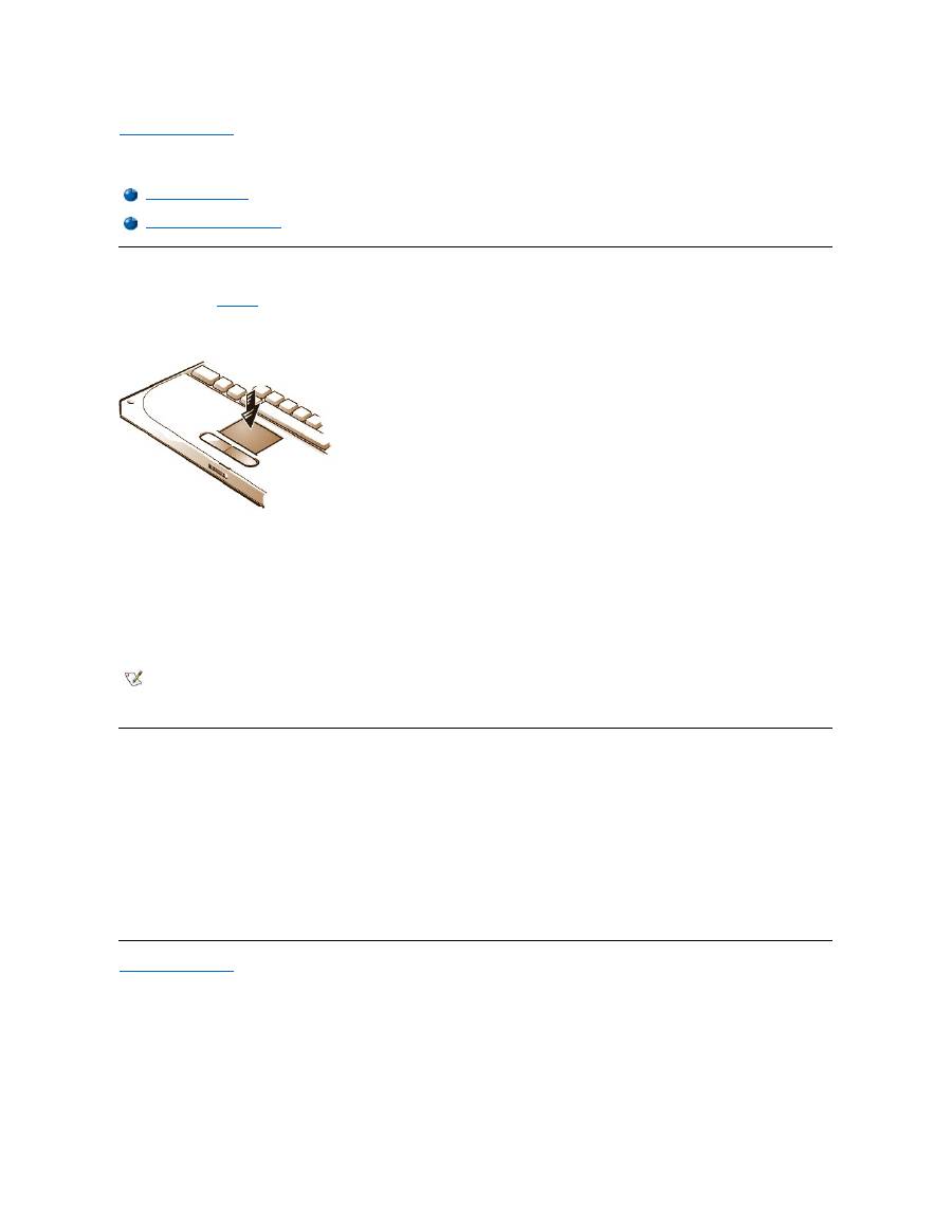
Back to Contents Page
Touch Pad: Dell™ Latitude™ CS/CS x Portable Computers User's Guide
Using the Touch Pad
The touch pad (see
Figure 1
) detects the position of your finger over a touch-sensitive area and provides the computer full mouse functionality. The
touch pad
’
s two buttons correspond to the left and right buttons on a standard mouse.
Figure 1. Touch Pad
To best use the touch pad, follow these techniques:
l
To move the cursor, lightly slide your finger over the smooth sensor area.
l
To select an object, gently tap once on the surface of the touch pad.
l
To select and move (or drag) an object, position the cursor on the object and tap down-up-down on the touch pad. On the second down
motion, leave your finger on the touch pad and move the selected object by sliding your finger across the surface.
l
To double-click an object, position the cursor on the object and then tap twice.
Customizing the Touch Pad
To customize the touch pad, perform the following steps:
1. Click the
Start
button, point to
Settings
, and click
Control Panel
.
2. Double-click the
Mouse
icon to open the
Mouse Properties
window and click the
Touch
tab.
3. Select the settings that work best for you and click
Apply
.
4. Click
OK
to save the settings and close the window.
You can also click the touch pad icon on the taskbar and click
TouchPad Properties
to open the
Mouse Properties
control panel.
Back to Contents Page
Using the Touch Pad
Customizing the Touch Pad
NOTES: When enabled, the touch pad uses interrupt request (IRQ) 12. No other device can use IRQ12 while the touch pad is
enabled.
When you attach an external PS/2 mouse to the computer, the touch pad is automatically disabled.

Back to Contents Page
Traveling With Your Computer: Dell™ Latitude™ CS/CS x Portable Computers User's Guide
Identifying Your Computer
As an antitheft measure, assign a primary password and a hard-disk drive password to prohibit unauthorized access to the computer.
Dell recommends that you follow these precautions before you travel with your computer:
l
Write down your
service tag
and put it in a safe place separate from the computer or carrying case. If the computer is lost or stolen, use the
service tag number when reporting to law enforcement officials and to Dell.
l
Use the
Asset Tag utility
to place an owner tag in the computer. In the owner tag, you may want to include your name or your company's name
and a contact number or electronic mail address that can be used to reach you.
l
Use a text editor (such as Microsoft
®
Windows
®
Notepad) to create a file called
if_found
in your root directory. Place information such as
your name, address, and telephone number in this file. (For instructions on using the appropriate text editor, see the documentation that
came with your operating system.)
l
Attach your business card or other name tag to the computer.
l
Contact your credit-card company and ask if it offers coded identification tags that allow your property to be returned to you without the risk of
revealing your name, address, or telephone number.
l
Use a permanent marking or stenciling device to write your driver
’
s license number or some other unique identifying mark on the computer. If
a lost or stolen computer is recovered, such marking identifies the computer as your property.
Service Tag
The service tag is an alphanumeric sequence on a bar code label located on the bottom of the computer. The service tag is unique to your
computer and allows Dell technical assistance personnel to identify the computer and its configuration quickly if you call for assistance.
If Your Computer Is Lost or Stolen
If your computer is lost or stolen, Dell suggests that you perform the following steps:
1. Call a law enforcement agency to report the lost or stolen computer.
Include the service tag in your description of the computer. Ask that a case number be assigned, and write it down. Also write down the
name, address, and telephone number of the law enforcement agency. If possible, obtain the name of the investigating officer.
If you know where the computer was lost or stolen, call a law enforcement agency in that area. If you do not know, call a law
enforcement agency where you live.
2. If the computer belongs to a company, notify the security office of the firm.
3. Call Dell technical assistance to report the missing computer.
Provide the computer
’
s service tag, the case number, and the name, address, and telephone number of the law enforcement agency to
which you reported the missing computer. If possible, give the name of the investigating officer.
The Dell support technician will log your report under the computer
’
s service tag and flag the computer as missing or stolen. If someone
calls Dell for technical assistance and gives your service tag, the computer is identified automatically as missing or stolen. The
technician will attempt to get the phone number and address of the caller. Dell will then contact the law enforcement agency to which
you made the report of the missing or stolen computer.
Preparing Your Computer for Travel
To prepare your computer for travel, perform the following steps:
1. Detach any external devices attached to the computer, and store them in a safe place. If a diskette is in the diskette drive, remove it. Remove
any cables attached to installed PC Cards (you do not have to remove the PC Cards themselves).
Identifying Your Computer
Preparing Your Computer for Travel
Travel Tips

2. To maximize battery life, check the charge on your battery. Then fully charge the battery and any spares you plan to carry with you. For more
information, see "
Batteries
."
3.
Turn off the computer or press <Fn><a> to enter suspend
-to-disk mode. (On a French keyboard, press <Fn><q>.)
NOTICE: When you disconnect the AC adapter from the computer, grasp the adapter cable's connector, not the cable itself, and pull
gently but firmly to avoid damaging the cable.
4. Disconnect the AC adapter.
NOTICE: When the display is closed, items left on the keyboard could damage the display.
5. Make sure that there is nothing on the keyboard and palmrest that can damage the display when you close it. Then close the display.
6. Pack all your computing accessories.
With the optional Dell carrying case, you can pack the computer and its accessories together.
Accessories
You may want to take some of the following accessories with you when you travel:
l
Spare batteries
l
Cables for PC Cards (such as modem and network cards)
l
AC adapter and AC power cable
l
Power adapters for foreign electrical outlets and modem cable adapters
for foreign telephone networks
l
Appropriate printer driver files if you will be using a printer
l
External media bay and its cable
l
Diskette drive
l
Backup diskettes
l
Additional storage devices
Traveling by Air
You may want to take the following precautions when you are traveling by air with your computer:
l
Notify airport security in advance that you are bringing a portable computer.
l
Be sure to have a charged battery or the AC adapter and power cable available in case you are asked to turn on the computer.
l
Do not check the computer as baggage.
NOTICE: Have airport security personnel check the computer by hand. If the computer passes through a metal detector, data loss
may occur. If you must pass the computer through a metal detector, first remove the hard-disk drive.
l
Do not put the computer through a metal detector. (The computer can safely go through an airport X-ray security machine.)
l
Before you use the computer on an airplane, check the in-flight magazine or ask the flight crew to verify that such use is permitted. Some
airlines forbid the use of electronic devices during the flight. All airlines forbid the use of electronic devices during takeoff and landing.
l
Use a carrying case (available from Dell) to protect the computer and accessories during travel.
l
If you pack the computer in a suitcase, do not pack so tightly that the computer display breaks or so loosely that the computer slides around.
l
Avoid packing the computer with items such as shaving cream, colognes, perfumes, or food.
l
Protect the computer, the battery, and the hard-disk drive from hazards such as extreme temperatures; overexposure to sunlight; and
exposure to dirt, dust, or liquids.
l
Pack the computer so that it does not slide around in the trunk of your car or in an overhead storage compartment.
l
If you are carrying a second hard-disk drive separately, protect the drive from exposure to static electricity by placing it in the case you
received it in or in an antistatic bag, or wrapping it in a nonconductive fabric.
NOTE: Follow the travel tips and take special precautions if you are planning to travel by air.

Travel Tips
l
Consider changing the settings of your power management options to maximize battery life if you will be using battery power for extended
periods.
l
If you are traveling internationally, carry proof of ownership to speed your passage through customs. If the computer is provided by your
employer, carry documentation of your right to use the computer. Investigate the customs regulations of the countries you plan to visit, and
consider acquiring an international
carnet
from your government if you travel through many different countries.
l
Power interruptions can occur frequently in some countries. Always have a charged battery available if traveling abroad.
l
Credit card holders should check with their credit card companies for information about the kinds of emergency travel assistance they offer
to users of portable computers. Many companies provide services that help you solve problems, such as quickly locating 3.5-inch diskettes
or providing a direct-dial telephone line for your modem connection.
NOTICE: Do not use the CD-ROM, DVD-ROM, or LS-120 drive while the computer is in motion. Doing so could interrupt the flow of
data to and from the CD-ROM, DVD-ROM, or LS-120 drive and the hard-
disk or diskette drive.
Carnet
A carnet is an international customs document (also known as a
merchandise passport
) that facilitates temporary imports into foreign countries
and is valid for up to 1 year.
Back to Contents Page

Back to Contents Page
Troubleshooting Your Computer: Dell™ Latitude™ CS/CS x Portable Computers User's Guide
Back to Contents Page
Dell Diagnostics
Error Messages and Flash Codes
Back to Contents Page
Installing the Microsoft ® Windows ® 95 and Windows 98 Operating System Drivers: Dell™ Latitude™ CS/CS x Portable Computers User's Guide
Overview
Dell provides software utilities and drivers that help you control certain features of your computer.
This section explains how to reinstall utilities and drivers on your Dell computer with the Microsoft
®
Windows
®
95 or Windows 98 operating
system.
Before proceeding, print the following procedures.
Use the program diskette set you made when you received your computer or the diskette set you received separately from Dell.
NOTICE: Do not dock the computer before turning it on the first time.
Installing Docking Drivers
To install the C/Port Family APR or C/Dock Family Expansion Station drivers, perform the following steps:
1.
If the computer has never been turned on
, turn it on now while it is undocked and complete the operating system setup. Then go to step 2.
If you have completed the operating system setup
, turn on the computer and go to step 2.
For setup instructions, see the Dell-supplied operating system
Setup Guide
that came with the computer.
2. Dock the computer.
The operating system creates a hardware profile for the C/Port APR or the C/Dock Expansion Station.
3. To load the appropriate drivers from the CD that came with your C/Port Family APR or C/Dock Family Expansion Station, follow the
instructions on the display. When prompted, restart the computer.
4. If you intend to connect to a network, you must install the appropriate drivers to use with a network expansion card in the C/Port Family APR
or C/Dock Family Expansion Station. See the documentation for your docking option for more information.
Installing Video Drivers for Windows 95
Video drivers control features such as screen resolution and the number of screen colors.
To install the video drivers for Windows 95, perform the following steps:
1. Save your work in all open application programs, because you will need to restart your computer at the end of this procedure to complete the
Overview
Installing Software Wavetable
Installing Docking Drivers
Installing Touch Pad Drivers
Installing Video Drivers for Windows 95
Installing MS-DOS CD-ROM Drivers
Installing Video Drivers for Windows 98
Installing Infrared Drivers (Windows 95 Only)
Installing Audio Drivers
Enabling Microsoft Infrared Support (Windows 95 and Windows
98)
NOTES: If your computer uses Windows 95 or Windows 98, the computer is already configured to work with the Dell Latitude C/Port
Family Advanced Port Replicator (APR) or C/Dock Family Expansion Station.
For more information on using the operating system installed on your computer by Dell, see the operating system user's guide that
came with your computer. You can also access system tools and documentation from Dell's technical support page
(
http://support.dell.com
). To do so, click
Support Your Dell
, enter your
service tag
, and click
Submit
.
NOTE: If you need to use extended video modes, check the documentation that came with the application program to determine if the
drivers are provided. If not, contact the software manufacturer to get the necessary drivers.

installation.
2. Insert the video drivers
diskette into the diskette drive.
3. Click the
Start
button, point to
Settings
, and then click
Control Panel
.
The
Control Panel
window appears.
4. Double-click the
Display
icon.
The
Display Properties
window appears.
5. Click the
Settings
tab.
6. Click
Advanced Properties
.
The
Advanced
Display Properties
window appears.
7. Click the
Adapter
tab and then click
Change...
.
The
Select Device
window appears.
8. Click
Have Disk...
.
9. Verify that
a:\
is displayed in the
Install from Disk
field, and then click
OK
.
10. When the
Select Device
window appears, verify that the
NeoMagic MagicMedia 256ZX
option is highlighted, and then click
OK
.
A progress bar is shown while the driver files are copied to your hard-disk drive.
After the drivers are successfully installed, the
Advanced Display Properties
window appears.
11. In the
Advanced Display Properties
window, click
Apply
and
OK
.
12. Click
Close
in the
Display Properties
window.
13. To activate the drivers, remove the diskette from the diskette drive, and restart your computer.
After installing the video drivers and restarting your computer, set the display parameters by performing the following steps:
1. Click the
Start
button, point to
Settings
, and then click
Control Panel
.
The
Control Panel
window appears.
2. Double-click the
Display
icon.
The
Display Properties
window appears.
3. Click the
Settings
tab.
4. Change the
Color
palette
option from
256 colors
to
True Color (24 bit)
.
5. Set the
Desktop
area for your display to
1024 x 768
.
6. Click
Apply
.
Installing Video Drivers for Windows 98
Video drivers control features such as screen resolution and the number of screen colors.
To install the video drivers for Windows 98, perform the following steps:
1. Save your work in all open application programs, because you will need to restart your computer at the end of this procedure to complete the
installation.
2. Insert the video drivers diskette into the diskette drive.
3. Click the
Start
button, point to
Settings
, and then click
Control Panel
.
The
Control Panel
window appears.
NOTE: If you need to use extended video modes, check the documentation that came with the application program to determine if the
drivers are provided. If not, contact the software manufacturer to get the necessary drivers.

4. Double-click the
Display
icon.
The
Display Properties
window appears.
5. Click the
Settings
tab and then click
Advanced...
.
6. Click the
Adapter
tab and then click
Change...
.
7. When the
Update Driver Wizard
appears, click
Next>
.
8. Select
Display a list of all the drivers in a specific location
, and click
Next>
.
9. When prompted for the location of the drivers, click
Have Disk...
.
10. In the
Install from Disk
window, verify that
a:\
is displayed in the
Install from Disk
field, and click
OK
.
The
Select Device
window appears.
11. Make sure that
NeoMagic MagicGraph 256ZX
is highlighted, and click
OK
.
12. In the
Update Device Driver Wizard
window, click
Next>
to begin copying the files, and then click
Finish
.
13. Close the
Display Properties
window.
14. When prompted to restart the computer, remove the diskette and then click
Yes
.
After installing the video drivers and restarting your computer, set the display parameters by performing the following steps:
1. Click the
Start
button, point to
Settings
, and then click
Control Panel
.
The
Control Panel
window appears.
2. Double-click the
Display
icon.
The
Display Properties
window appears.
3. Click the
Settings
tab.
4. Change the
Color
palette
option from
256 colors
to
True Color (24 bit)
.
5. Set the
Desktop
area for your display to
1024 x 768
.
6. Click
Apply
.
Installing Audio Drivers
Dell provides audio drivers so that you can customize the audio features of yoru computer. To install the audio drivers, perform the following steps:
1. Save your work in all open application programs, because you will need to restart your computer at the end of this procedure to complete the
installation.
2. Insert the audio driver diskette into the diskette drive.
3. Click the
Start
button, then click
Run...
.
The
Run
dialog box appears.
4. Type
a:\setup
, and then click
OK
or press <Enter>.
5. Follow the instructions on your display.
6. After the files are copied to your hard-disk drive, click
Finish
.
Installing Software Wavetable
The software wavetable allows you to customize certain audio features. To install the software wavetable, perform the following steps:
1. Save your work in all open application programs, because you will need to restart your computer at the end of this procedure to complete the
installation.
2. Insert the first software wavetable diskette into the diskette drive.

3. Click the
Start
button, and then click
Run...
.
The
Run
dialog box appears.
4. Type
a:\setup
, and then click
OK
or press <Enter>.
5. Follow the instructions on your display.
6. After the installation is complete, remove the final diskette from the diskette drive and restart your computer to use the software wavetable.
Installing Touch Pad Drivers
Touch pad drivers and associated utilities allow you to use and customize the integrated touch pad or an external mouse. To install the touch pad
drivers, perform the following steps:
1. Save your work in all open application programs, because you will need to restart your computer at the end of this procedure to complete the
installation.
2. Insert the touch-pad drivers diskette into the diskette drive.
3. Click the
Start
button, and then click
Run...
.
The
Run
dialog box appears.
4. Type
a:\setup
, and then click
OK
or press <Enter>.
5. Restart your computer to activate the drivers.
Installing MS-DOS ® CD-ROM Drivers
CD-ROM drivers must be installed in order to use the MS-DOS CD-ROM utility. To install the CD-ROM drivers, perform the following steps:
1. Save your work in all open application programs, because you will need to restart your computer at the end of this procedure to complete the
installation.
2. Insert the CD-ROM drivers diskette into the diskette drive.
3. Click the
Start
button, and then click
Run...
.
The
Run
dialog box appears.
4. Type
a:\setup
, and then click
OK
or press <Enter> to install the utility on your hard-disk drive.
5. Follow the instructions on your display, and when prompted, restart your computer to activate the drivers.
Installing Infrared Drivers (Windows 95 Only)
An infrared port lets you transfer files from your computer to another infrared-compatible device without using cable connections. If your computer
is running the Microsoft Windows 95 operating system, install the infrared drivers by performing the following steps:
1. Make sure that the computer is docked and that a diskette drive is connected to the computer's media bay connector or parallel port.
2. Save your work in all open application programs, because you will need to restart your computer at the end of this procedure to complete the
installation.
3. Insert the infrared drivers diskette into the diskette drive.
4. Click the
Start
button, point to
Settings
, and then click
Control Panel
.
5. Double-click the
System
icon.
The
System Properties
dialog box appears.
NOTES: Although your Latitude CS/CSx portable computer does not include an infrared port, the computer supports the infrared ports in
the C/Port Family APR and C/Dock Family Expansion Station.
To use the infrared port, Windows 95 users must install the infrared drivers and then enable them. Windows 98 already includes the
necessary drivers; Windows 98 users need only
enable
the infrared support.

5. Click the
Device Manager
tab.
6. Click the
View Devices by Type
radio button.
7. Click the plus sign to the left of the
Ports
icon.
The names of various device ports appear beneath the
Ports
icon.
8. Click
Infrared Serial (COM) Connections Port
, and then click
Properties
.
The
Infrared Serial (COM) Connections Port Properties
dialog box appears.
9. Click
the
Driver
tab
and
then click
Update Driver...
.
The
Update Device Driver Wizard
appears.
10. Click the
Yes (Recommended)
radio button, and then click
Next
.
Windows 95 searches for the drivers on the diskette you inserted in step 3.
11. To update the driver, follow the instructions on your display.
12. After the driver is updated, close the
Device Manager
and open
Windows Explorer
.
13. With the
Infrared Drivers
diskette still in the diskette drive, click
drive A
.
14. Right-click the
smcirlap.inf
file.
A pop-up menu appears.
15. Click
Install
.
The
smcirlap.inf
file is installed.
16. Restart your computer, and perform the procedure for
enabling
the infrared support.
Enabling Microsoft Infrared Support (Windows 95 and Windows 98)
For Windows 95, you must
install
the infrared drivers before you can enable them (Windows 98 already includes infrared support). For both
Windows 95 and Windows 98, you must enable Microsoft infrared support before you can use it. To enable Microsoft infrared support, perform the
following steps:
1. Click the
Start
button, point to
Settings
, and then click
Control Panel
.
2. Double-click the
Add New Hardware
icon.
The
Add New Hardware Wizard
appears.
3. Click
Next
to continue.
4. When the
Add New Hardware Wizard
asks to search for new hardware, click
No
and then click
Next
.
5. When the
Hardware
Types
window appears, click
Infrared
and then click
Next
.
6. When the
Add Infrared Device Wizard
window appears, click
Next
.
7. (Windows 95 only) When the
Manufacturers and Models
window appears, select
Standard
Infrared Devices
from the
Manufacturers
list and
Built-In Infrared Port on Laptop or Desktop
from the
Models
list, and then click
Next
.
8. Follow the instructions on your display.
9. To enable infrared support, shut down and reboot your computer.
Back to Contents Page
NOTE: Your Latitude CS/CSx portable computer supports the infrared ports in the C/Port Family APR and C/Dock Family Expansion Station.
The computer itself not include an infrared port.
Back to Contents Page
Installing the Microsoft ® Windows NT ® Operating System Drivers: Dell™ Latitude™ CS/CS x Portable Computers User's Guide
Overview
Dell provides software utilities and drivers that help you control certain features of your computer.
This section explains how to reinstall utilities and drivers on your Dell computer with the Microsoft
®
Windows NT
®
4.0 operating system.
Use the program diskette set you made when you received your computer or the diskette set you received separately from Dell. You can also
access system tools and documentation from Dell's technical support page (
http://support.dell.com
). To do so, click
Support Your Dell
, enter
your
service tag
, and click
Submit
.
Installing Video Drivers
Video drivers control features such as screen resolution and the number of screen colors.
To install the video drivers for Windows NT 4.0, perform the following steps:
1. Save your work in all open application programs, because you will need to restart your computer at the end of this procedure to complete the
installation.
2. Insert the video drivers diskette into the diskette drive.
3. Click the
Start
button, point to
Settings
, and then click
Control Panel
.
The
Control Panel
window appears.
4. Double-click the
Display
icon.
The
Display Properties
window appears.
5. Click the
Settings
tab.
6. Click
Display Type...
.
The
Display Type
window appears.
7. In the
Adapter Type
box, click
Change...
.
8. The
Change Display
window appears.
9. Click
Have Disk...
.
10.
Verify that
a:\
is displayed in the
Install from Disk
box, and then click
OK
.
Overview
Installing Audio Drivers
Installing Video Drivers
Installing Touch Pad Drivers
Installing the Power Management Utility
Installing System Utilities
Installing Softex Docking Services
Installing the Software Wavetable
Installing the PC Card Utility
NOTE: You may need administrator privileges to perform some of procedures in this section. Dell recommends that you check with
your network administrator before performing the procedures.
For more information on using the operating system installed on your computer by Dell, see the operating system user's guide that
came with your computer.
NOTE: If you need to use extended video modes, check the documentation that came with the application program to determine if the
drivers are provided. If not, contact the software manufacturer to get the necessary drivers.

11. When the
Change Display
window appears, verify that the
NeoMagic MagicMedia
256ZX
option is highlighted, and then click
OK
.
A progress bar is shown while the driver files are copied to your hard-disk drive.
After the drivers are successfully installed, the
Installing Driver
window appears.
12. Click
OK
in the
Installing Driver
window.
13. Click
Close
in the
Display Type
window, and then click
Close
in the
Display Properties
window.
14. To activate the drivers, remove the diskette from the diskette drive, and restart your computer.
Installing the Power Management Utility
Dell provides a power management utility that helps you conserve battery power and view available power levels. To install the power management
utility, perform the following steps:
1. Save your work in all open application programs, because you will need to restart your computer at the end of this procedure to complete the
installation.
2. Insert the Softex power management utility diskette into the diskette drive.
3. Click the
Start
button, and then click
Run...
.
The
Run
dialog box appears.
4. Type
a:\setup
, and then click
OK
or press <Enter>.
Follow the instructions on the display.
5.
When prompted, restart your computer to activate the utility.
Installing Softex Docking Services
Dell provides Softex Docking Services software that contains support for the following features:
l
Hot-docking and warm-undocking a Latitude CS/CS
x
portable computer from supported docking stations
l
Hot-swapping devices such as diskette, hard-disk, large-storage, DVD-ROM, and CD-ROM drives to and from your portable computer
’
s
external media bay and the C/Dock Family Expansion Station
’
s media bay
l
Compatibility with the Power Management Controller, which allows you to suspend and resume your portable computer without affecting your
ability to use the docking station or its media bay
l
Docking or undocking your portable computer while it is in suspend mode
l
Docking services available in French, German, Italian, Spanish, and Japanese
For information about installing Softex Docking Services, see the Softex Docking Services user
’
s guides at
http://www.dell.com/products/notebook/latitude/NT40.htm
and see your
Dell-Installed Microsoft Windows NT Workstation Setup Guide
.
Installing the PC Card Utility
Dell provides a PC Card utility that allows you to view and configure settings for your PC Card(s). To install the PC Card utility, perform the
following steps:
1. Save your work in all open application programs, because you will need to restart your computer at the end of this procedure to complete the
installation.
2. Insert the first Softex PC Card controller
diskette into the diskette drive.
3. Click the
Start
button, and then click
Run...
.
The
Run
dialog box appears.
4. Type
a:\setup
, and then click
OK
or press <Enter>.
Follow the instructions on your display.
5. Restart your computer.

6. When the computer completes the starting sequence, the
Softex PC Card Controller Diagnostics
window appears.
7. Follow the instructions on your display, and when prompted, restart your computer to activate the utility.
Installing Audio Drivers
To install the audio drivers, perform the following steps:
1. Save your work in all open application programs, because you will need to restart your computer at the end of this procedure to complete the
installation.
2. Insert the
audio driver diskette into the diskette drive.
3. Click the
Start
button, point to
Settings
, and then click
Control Panel
.
4. Double-click the
Multimedia
icon.
The
Multimedia Properties
dialog box appears.
5. Click the
Devices
tab.
6. Click
Add...
.
The
Add
dialog box appears, displaying a list of drivers.
7. Click the
Unlisted or Updated Driver
option, and then click
OK
.
The
Install Driver
dialog box appears.
8. Verify that
A:\
is highlighted, and then click
OK
.
The
Add Unlisted or Updated Driver
window appears.
9. Verify that
NeoMagic MagicMedia 256
is highlighted, and then click
OK
.
The
Audio
dialog box appears.
10. Click
OK
.
11. After installation is completed, restart your computer to activate the drivers.
Installing Touch Pad Drivers
Touch pad drivers and associated utilities allow you to use and customize the integrated touch pad or an external mouse. To install the touch pad
drivers, perform the following steps:
1. Save your work in all open application programs, because you will need to restart your computer at the end of this procedure to complete the
installation.
2. Insert the touch-pad drivers
diskette into the diskette drive.
3. Click the
Start
button, and then click
Run...
.
The
Run
dialog box appears.
4. Type
a:\setup
, and then click
OK
or press <Enter>.
Follow the instructions on your display.
5. When prompted, restart the computer to activate the drivers.
Installing System Utilities
System utilities let you configure features such as the
asset tag
code and
suspend-to-disk
partition. To copy the system utilities to your hard-disk
drive, perform the following steps.
NOTE: You can also run the system utilities directly from the
System Utilities diskette.

1. Insert the
System Utilities
diskette into the diskette drive.
2. Copy each of the utilities on the
System Utilities
diskette to the
c:\dell
directory on your hard-disk drive. The utilities have the following
filenames:
mks2d.exe
,
rms2d.exe
,
asset.com
, and
readme.s2d.
For more information on copying files, see the documentation that came with the operating system.
After you copy the utilities to your hard-disk drive, you must restart your computer in the MS-DOS
®
mode to use the utilities.
Installing the Software Wavetable
The software wavetable allows you to customize certain audio features. To install the software wavetable, perform the following steps:
1. Save your work in all open application programs, because you will need to restart your computer at the end of this procedure to complete the
installation.
2. Insert the first software wavetable diskette into the diskette drive.
3. Click the
Start
button, and then click
Run...
.
The
Run
dialog box appears.
4. Type
a:\setup
, and then click
OK
or press <Enter>.
Follow the instructions on your display.
5. After the installation is complete, remove the final diskette from the diskette drive and restart your computer to use the software wavetable.
Back to Contents Page
