Dell LATITUDE D400 – страница 2
Инструкция к Ноутбуку Dell LATITUDE D400
Оглавление
- Dell™ Latitude™ CS/CS Portable Computers User's Guide
- AC Adapter: Dell™ Latitude™ CS/CS x Portable Computers User's Guide

Back to Contents Page
Taiwan, and
Thailand
—
refer to
individual listings
for these
countries)
Taiwan
NOTE:
Customers in
Taiwan call
Malaysia for
customer
assistance.
Technical Support
toll free:
0080 651 226/0800 33 557
Customer Service (Penang, Malaysia)
810 4949
Transaction Sales
toll free:
0080 651 228/0800 33 556
Corporate Sales
toll free:
0080 651 227/0800 33 555
Thailand
NOTE:
Customers in
Thailand call
Malaysia for
customer
assistance.
Technical Support
toll free: 0880 060 07
Customer Service (Penang, Malaysia)
810 4949
Sales
toll free: 0880 060 06

Back to Contents Page
Customizing Your Computer: Dell™ Latitude™ CS/CS x Portable Computers User's Guide
Back to Contents Page
Using the System Setup Program
System Setup Options
Power Management Settings
Suspend-to-Disk Utility

Back to Contents Page
Dell™ Diagnostics: Dell Latitude™ CS/CS x Portable Computers User's Guide
Overview
Unlike many diagnostic programs, the Dell Diagnostics helps you check your computer's hardware without any additional equipment and without
destroying any data. By using the diagnostics, you can have confidence in your computer's operation. And if you find a problem you cannot solve
by yourself, the diagnostic tests can provide you with important information you will need when talking to Dell's service and support personnel.
NOTICE: Use the Dell Diagnostics to test only your Dell computer. Using this program with other computers may cause incorrect
computer responses or result in error messages.
Features of the Dell Diagnostics
The Dell Diagnostics provides a series of menus and options from which you choose particular test groups or subtests. You can also control the
sequence in which the tests are run. The diagnostic test groups or subtests also have these helpful features:
l
Options that let you run tests individually or collectively
l
An option that allows you to choose the number of times a test group or subtest is repeated
l
The ability to display or print out test results, or to save them in a file
l
Options to temporarily suspend testing if an error is detected, or to terminate testing when an adjustable error limit is reached
l
A
Devices
menu that briefly describes each test and its parameters
l
A
Config
menu that describes the configuration of the devices in the selected device group
l
Status messages that inform you whether test groups or subtests were completed successfully
l
Error messages that appear if any problems are detected
When to Use the Dell Diagnostics
Whenever a major component or device in your computer does not function properly, you may have a component failure. As long as the
microprocessor and the input and output components of your computer (the display, keyboard, and diskette drive) are working, you can use the
Dell Diagnostics. If you are experienced with computers and know what component(s) you need to test, simply select the appropriate diagnostic
test group(s) or subtest(s). If you are unsure about how to begin diagnosing a problem, read the rest of this section.
Before You Start Testing
If Dell installed the Microsoft
®
Windows
®
95 or Windows 98 operating system on your computer's hard-disk drive
, see the online help in Dell's
Program Diskette Maker
utility, which is available in the
Dell
Accessories
group or folder, for instructions on making a program diskette set
from the diskette image.
Refer to your operating system's documentation for information on how to duplicate diskettes. Put the original diskette away for safekeeping. Turn
on your printer if one is attached, and make sure it is online.
Enter the System Setup program
, confirm your computer's system configuration
information, and enable all its components and devices, such as ports.
Starting the Dell Diagnostics
After you complete the preliminary instructions specified in "
Before You Start Testing
," perform the following steps to start the diagnostics:
Overview
Starting the Dell Diagnostics
Features of the Dell Diagnostics
Dell Diagnostics Main Screen Overview
When to Use the Dell Diagnostics
Confirming the System Configuration Information
Before You Start Testing
How to Use Dell Diagnostics

1. Turn off the computer.
2. Insert the first diagnostics diskette into the diskette drive.
3. Turn on the computer.
When you start the diagnostics, the Dell logo screen appears, followed by a message telling you that the diagnostics is loading. Follow the screen
prompts to insert the second and third diskettes.
After the diagnostics loads, the
Diagnostics
Menu
appears (see
Figure 1
). The menu allows you to run all or specific diagnostic tests or to exit to
the MS-DOS
®
prompt.
For a quick check of your computer, select
Quickly Test All Devices
. This option runs only the subtests that do not require user interaction and
that do not take a long time to run. Dell recommends that you choose this option first to increase the odds of tracing the source of the problem
quickly. For a thorough check of your computer, select
Fully Test All Devices
. To check a particular area of your computer, select
Select
Devices to Test
.
To select an option from this menu, highlight the option and press <Enter>, or press the key that corresponds to the highlighted letter in the option
you choose.
Figure 1. Diagnostics Menu
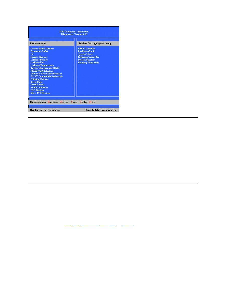
Dell Diagnostics Main Screen Overview
When you select
Select Devices to Test
from the
Diagnostics
Menu
, the main screen of the diagnostics appears (see
Figure 2
). The main
screen lists the diagnostic test device groups, lists the devices of the selected device group, and allows you to select categories from a menu.
From this screen, you can enter two other types of screens.
Information on the main screen of the diagnostics is presented in the following five areas:
l
Two lines at the top of the screen identify the version number of the Dell Diagnostics.
l
On the left side of the screen, the
Device
Group
s area lists the diagnostic test groups in the order they will run if you select
All
from the
Run
tests
menu. Press the up- or down-arrow key to highlight a test device group.
l
On the right side of the screen, the
Devices for Highlighted Group
area lists the computer's currently detected hardware and some of the
relevant settings.
l
The lower-right side of the screen displays information about your drive(s).
l
Two lines at the bottom of the screen make up the menu area. The first line lists the categories you can select; press the left- or right-arrow
key to highlight a menu category. The second line gives information about the category currently highlighted.
Figure 2. Dell Diagnostics Main Screen
NOTE: Before you read the rest of this subsection, you may want to start the Dell Diagnostics so that you can see it on your display.
NOTE: The options displayed on your screen should reflect the hardware configuration of your computer.
Confirming the System Configuration Information
When you boot your computer from your diagnostics diskette, the diagnostics checks your system configuration information and displays it in the
Device Groups
area on the main screen.
The following sources supply this configuration information for the diagnostics:
l
The system configuration information settings (stored in nonvolatile random-access memory [NVRAM]) that you selected while using the
System Setup program
l
Identification tests of the microprocessor, the video controller, the keyboard controller, and other key components
l
Basic input/output system (BIOS) configuration information temporarily saved in RAM
Do not be concerned if the
Device Groups
area does not list the names of all the components or devices you know are part of your computer. For
example, you may not see a printer listed, although you know one is attached to your computer. Because your printer is a parallel communications
device, the computer recognizes the printer by its LPT1 address and identifies it as a parallel port. You can test your printer connection in the
Parallel Ports
tests.
How to Use Dell Diagnostics
Six comprehensive, menu-driven, online Help categories provide instructions on how to use the program and explain each menu item, test group,
subtest, and test and error result. To enter the
Help
menu, perform the following steps:
1. Highlight
Select Devices to Test
in the
Diagnostics
Menu
.
2. Press <Enter>.
3. Press <h>.
The
Help
menu categories are
Menu
,
Keys
,
Device
Group
,
Device
,
Test
, and
Versions
. The online Help also provides detailed descriptions of
the devices that you are testing. The
Help
categories are explained in the following subsections.
Menu Category
Menu
describes the main menu screen area, the
Device
Groups
, and the different diagnostic menus and commands and instructions on how to
use them.
Keys Category
Keys
explains the functions of the all of the keystrokes that can be used in Dell Diagnostics.
Device Group Category

Device Group
describes the test group that is presently highlighted in the
Device
Groups
list on the main menu screen. It also provides
reasoning for using some tests.
Device Category
Device
is the educational section of online Help. It describes the function and purpose of the highlighted device in the
Device
Groups
.
For example, the following information appears when you select
Device
for
Diskette
in the
Device
Groups
list:
Diskette drive A:
The diskette disk drive device reads and writes data to and from diskettes. Diskettes are flexible
recording media, sometimes contained in hard shells. Diskette recording capacities are small and
access times are slow relative to hard disk drives, but they provide a convenient means of storing
and transferring data.
Test Category
Test
provides a thorough explanation of the subtest for each selected device group. For example, the following description is provided for the
Diskette Drive Seek Test
:
Diskette drive A: - Diskette Drive Seek Test
This test verifies the drive's ability to position its read/write heads. The test operates in two
passes: first, seeking from the beginning to ending cylinders inclusively, and second, seeking
alternately from the beginning to ending cylinders with convergence towards the middle.
Versions Category
Versions
lists the version numbers of the subtests that are used by the Dell Diagnostics.
Back to Contents Page

Back to Contents Page
Diskette Drive: Dell™ Latitude™ CS/CS x Portable Computers User's Guide
Your computer was shipped with a 3.5-inch diskette drive installed in the external media bay. For more information on using and installing devices
in the external media bay, see "
Using the External Media Bay
."
The diskette drive lets you install programs and transfer data using 3.5-inch diskettes.
To use the diskette drive, insert a 3.5-inch diskette into the drive (label side up and metal end first). Push the diskette into the drive until the eject
button extends outside the drive casing.
NOTICE:
Do not travel with a diskette in the diskette drive. Doing so could break the eject button and damage the drive.
To remove a diskette from the drive, press the eject button to release the diskette, and then pull the diskette out of the drive.
When data is being accessed from the diskette drive, the
drive access indicator
blinks.
Back to Contents Page
NOTE: As an alternative diskette drive configuration, you can
connect the diskette drive to the parallel connector
on the back of the
computer using an optional cable available from Dell. If you are running either the Microsoft
®
Windows
®
95 or Windows 98 operating
system on your computer and the
Diskette Reconfig
option is enabled in the System Setup program, you do not have to reboot the
computer when you connect the diskette drive to the parallel connector. If you are running the Microsoft Windows NT
®
operating system
on your computer, reboot the computer after you connect the diskette drive.

Back to Contents Page
Display: Dell™ Latitude™ CS/CS x Portable Computers User's Guide
Adjusting the Brightness
To adjust the brightness of the display, you can use the key combinations shown in
Table 1
.
Table 1. Brightness Key Combinations and Their Functions
Expanded Video Mode
When working in text mode, you can select the font used to display text. Press <Fn><F7> to toggle between regular video mode and expanded
video mode. In expanded video mode, items in resolutions other than 1024 x 768 expand to fill the screen, which is useful if you are working in 800
x 600 resolution on a 13.3-inch extended graphics array (XGA) display.
Video Drivers and Video Resolution
The Dell-installed video drivers work with the operating system to let you customize the video resolution, number of screen colors, and refresh rate
of your display.
Table 2. Combinations of Resolutions and Colors Supported
Adjusting the Brightness
Customizing Video Resolution
Expanded Video Mode
Dual-Display Mode
Video Drivers and Video Resolution
If You Have Display Problems
NOTE: When you run the computer on battery power, set your computer's brightness control to the lowest setting that affords
comfortable viewing. You can extend your battery life by using the minimum brightness setting.
Key Combinations
Function
<Fn> + down arrow
Decreases brightness
<Fn> + up arrow
Increases brightness
<Fn> + right arrow
Has no effect on this computer
<Fn> + left arrow
Has no effect on this computer
NOTES: You cannot change contrast on an active-matrix (thin film transistor [TFT]) display, such as your computer's display.
(Contrast
adjustments are only necessary on older passive-matrix displays.)
To use key combinations on an external keyboard, enable the
External Hot Key
option in the System Setup program and use <Scroll
Lock> instead of <Fn>.
NOTES: You may have difficulty using the display fonts feature with MS-DOS
®
programs that use downloaded fonts.
For optimum video performance in these cases, do not use expanded video mode.
NOTE: The Dell-installed video drivers are designed to offer the best performance on your computer. Dell recommends that you use
only these drivers with your factory-installed operating system.
Resolution
Colors
Bits
Display Refresh
Rate
External Monitor
Refresh Rate
* In this resolution, the display is set to pan mode. To use 1280 x 1024 resolution, set the external monitor to
Plug and Play Monitor
as
described in the following procedures.
For Windows 95, perform the following steps:
1.
Click the
Start
,button, point to
Settings
, and then click
Control Panel
.
2.
Double-click the
Display
icon.
3.
Click the
Settings
tab, click
Advanced Properties
, and click the
Monitor
tab.
4.
Click
Change...
, click
Plug and Play Monitor
, and click
OK
twice.
5.
Set
Display area
to
1280 x 1024
, and click
OK
.
For Windows 98, perform the following steps:
1.
Click the
Start
button, point to
Settings
, and then click
Control Panel
.
2.
Double-click the
Display
icon.
3.
Click the
Settings
tab, click
Advanced...
, and click the
Monitor
tab.
4.
Click
Change...
, click
Next
, and click
Display a list of all the drivers
.
5.
Click
Next
, and click
Show all hardware
.
6.
Under
Manufacturers
, click
(Standard monitor types)
.
7.
Under
Models
, click
Plug & Play Monitor
; and click
Next
.
8.
Click
Next
again, click
Finish
, and click
Close
.
9.
At the
Display Properties
screen, set
Screen area
to
1280 x 1024
, and click
Apply
.
10.
Click
OK
, click
Yes
, and click
OK
.
To display more colors, select a lower resolution. If you select a resolution and color combination that the computer does not support, the computer
automatically selects the next supported combination.
Customizing Video Resolution
1. Click the
Start
button, point to
Settings
, and then click
Control Panel
.
The
Control Panel
window appears.
2. Double-click the
Display
icon.
The
Display Properties
window appears.
3. Click the
Settings
tab, and then set the resolution by dragging the slider in the
Desktop Area
box. In the
Color Palette
box, choose the
number of colors from the menu provided. For more information, see your operating system documentation.
If you choose a resolution or color palette that is higher than is supported, the settings adjust automatically to the closest possible setting.
4. To change the refresh rate, click the
NeoMagic
tab, and then follow the instructions on your display.
640 x 480
256
8
60 Hz
60 Hz, 75 Hz, 85 Hz
65,536
(64 K)
16 (High Color)
60 Hz
60 Hz, 75 Hz, 85 Hz
1677721
(16 Million)
24 (True Color)
60 Hz
60 Hz, 75 Hz, 85 Hz
800 x 600
256
8
60 Hz
60 Hz, 75 Hz, 85 Hz
65,536
(64 K)
16 (High Color)
60 Hz
60 Hz, 75 Hz, 85 Hz
1677721
(16 Million)
24 (True Color)
60 Hz
60 Hz, 75 Hz, 85 Hz
1024 x 768
256
8
60 Hz
60 Hz, 70 Hz, 75 Hz, 85
Hz
65,536
(64 K)
16 (High Color)
60 Hz
60 Hz, 70 Hz, 75 Hz, 85
Hz
1677721
(16 Million)
24 (True Color)
60 Hz
60 Hz, 70 Hz, 75 Hz, 85
Hz
1280 x 1024*
256
8
60 Hz
60 Hz
NOTE: You can adjust the refresh rate only on an external monitor. If the
NeoMagic
tab is inactive, your external monitor adjusts
the refresh rate automatically.

Dual-Display Mode
With Microsoft
®
Windows
®
98 and later operating systems, you can use an external monitor as an extension of your display (see your operating
system documentation for more information). To set up your computer for dual
-display mode, perform the following steps:
1. Connect the
external monitor
.
2. Click the
Start
button, point to
Settings
, and then click
Control Panel
.
3. In the
Control Panel
window, double-click the
Display
icon.
4. In the
Display Properties
window, click the
Settings
tab.
5. Change the
Colors
option to
High Color (16 bit)
.
6. Change the
Desktop Area
to
1024 by 768 pixels
.
7. Click
Advanced...
.
8. Click the
NeoMagic
tab.
9. Select the
Set Dual-Display
checkbox and click
Apply
.
10. Click
Yes
when prompted to restart your computer.
11. Click the
Start
button, point to
Settings
, and then click
Control Panel
.
12. Double-click
Display
, and then click the
Settings
tab.
Two display icons appear in the
Settings
window.
13. Click the display icon marked "
2
."
14. When asked if you want to enable this monitor, click
Yes
.
15. Click
Apply
, and then click
OK
.
If You Have Display Problems
If your computer is receiving power, but nothing appears on your display (such as light, text, or graphics) or the display image does not appear as
you would expect, try the following measures to resolve the problem:
1. If the display is blank, you may be in suspend, standby, or suspend-to-disk mode. Press the power button to resume. If the display is blank
and the power indicator is on, the display may have timed out. In this case, press any key on the keyboard to resume normal operation.
2. If the
low-battery warning
occurs,
connect
the AC adapter to the computer or replace the battery.
3. Adjust the brightness.
4. If your computer is attached to an external monitor, press <Fn><F8> to switch the video image to the display.
Back to Contents Page
NOTE: It takes several seconds to switch the video image.

Back to Contents Page
Drivers: Dell™ Latitude™ CS/CS x Portable Computers User's Guide
Back to Contents Page
Installing Microsoft
®
Windows
®
95 and Windows 98 Drivers
Installing Microsoft
®
Windows NT
®
Drivers
NOTE: For more information on using the operating system installed on your computer by Dell, see the operating system user's guide
that came with your computer.

Back to Contents Page
Error Messages and Flash Codes: Dell™ Latitude™ CS/CS x Portable Computers User's Guide
Error Messages
Your application programs, operating system, and the computer itself can identify problems and alert you to them. When this occurs, a message
may appear on the computer's display or on an external monitor (if one is attached), or a flash code may be emitted.
If an error message appears on the display or external monitor, make a note of the message. For an explanation of the message and suggestions
for correcting any errors, see
Table 1
. The messages are listed alphabetically.
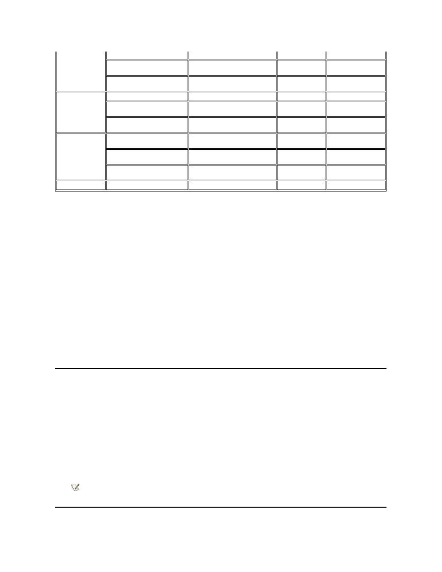
Table 1. System Error Messages
Error Messages
Memory Allocations
System Flash Codes
I/O Memory Map
Avoiding Interrupt Assignment Conflicts
NOTE: If the message is not listed in Table 1, see the documentation for the application program or the operating system
documentation for an explanation of the message and a recommended action.
Message
Cause
Action
Auxiliary device
failure
The touch pad or external PS/2 mouse
may be faulty.
If you are using an external mouse only, check the connection for a
loose or improperly connected cable. If the problem persists,
enable the
Pointing Device
option. If the problem persists,
call
Dell
for technical assistance.
Bad command or file
name
The command you entered does not
exist or is not in the pathname you
specified.
Make sure that you have typed the command correctly, placed
spaces in the proper location, and used the correct pathname.
Cache disabled due to
failure
The primary cache internal to the
microprocessor has failed.
Call Dell
for technical assistance.
CD-ROM drive
controller failure 1
The CD-ROM drive does not respond to
commands from the computer.
Turn off the computer and detach the CD-ROM drive from the
media bay connector. Reboot the computer. Turn off the computer
again, reattach the CD-ROM drive to the computer, and verify the
media-bay cable connection to the back of the CD-ROM drive.
Reboot the computer. If the problem persists, run the
CD-ROM
Drive
tests in the
Dell Diagnostics
.
Data error
The diskette or hard-disk drive cannot
read the data.
Run the appropriate utility to check the file structure of the diskette
drive or hard-disk drive. See the documentation that came with
your operating system.
Decreasing available
memory
One or more memory modules may be
faulty or improperly seated.
Reseat the
memory module
in the upgrade socket. If the problem
persists, remove the memory module from the upgrade socket. If
the problem still persists,
call Dell
for technical assistance.
Disk C: failed
initialization
The hard-disk drive failed initialization.
Remove and reseat the
hard-disk drive
, and reboot the computer.
If the problem persists, boot from the
diagnostics diskett
e and run
the
Hard-Disk Drive
tests.
Diskette drive 0 seek
failure
A cable may be loose, or the system
configuration information may not match
the hardware configuration.
Check and reseat the diskette drive cable. If the problem persists,
run the
Diskette Drive
tests in the
Dell Diagnostics
and check the
setting for the appropriate drive (
Diskette Drive A
or
Diskette
Drive B
) in the
System Setup program
. If the problem cannot be
corrected, call Dell for technical assistance
.
Diskette read failure
A cable may be loose, or the diskette
may be faulty.
If the diskette-drive access indicator lights up, try a different
diskette.
Diskette subsystem
reset failed
The diskette drive controller may be
faulty.
Run the
Diskette Drive
tests in the
Dell Diagnostics
.
Diskette write-
protected
Because the diskette is write-protected,
the operation cannot be completed.
Slide the write-protect notch up.
Drive not ready
No diskette is in the diskette drive, or no
hard-disk drive is in the drive bay. The
operation requires a diskette in the drive
Put a diskette in the drive, or push the diskette all the way into the
drive until the eject button pops out. Or, install a hard-disk drive in
the drive bay.

or a hard-disk drive in the bay before it
can continue.
Error reading PCMCIA
card
The computer cannot identify the PC
Card.
Reseat the card or try another PC Card that you know works.
Extended memory size
has changed
The amount of memory recorded in
NVRAM does not match the memory
installed in the computer.
Reboot the computer. If the error appears on the display again,
call Dell
for technical assistance.
Gate A20 failure
An installed memory module may be
loose.
Reseat the
memory module
in the upgrade socket. If the problem
persists, remove the memory module from the upgrade socket. If
the problem still persists,
call Dell
for technical assistance.
General failure
The operating system is unable to carry
out the command.
This message is usually followed by specific information
—
for
example,
Printer out of paper
. Respond by taking the
appropriate action.
Hard-disk drive
configuration error
The computer cannot identify the drive
type.
Turn off the computer, remove the drive, and boot the computer
from a bootable diskette. Then turn off the computer, reinstall the
drive, and reboot the computer. Run the
Hard-Disk Drive
tests in
the
Dell Diagnostics
.
Hard-disk drive
controller failure 0
The hard-disk drive does not respond to
commands from the computer.
Turn off the computer, remove the drive, and boot the computer
from a bootable diskette. Then turn off the computer again,
reinstall the drive, and reboot the computer. If the problem
persists, try another drive. Then run the
Hard-Disk Drive
tests in
the
Dell Diagnostics
.
Hard-disk drive
failure
The hard-disk drive does not respond to
commands from the computer.
Turn off the computer, remove the drive, and boot the computer
from a bootable diskette. Then turn off the computer again,
reinstall the drive, and reboot the computer. If the problem
persists, try another drive. Then run the
Hard-Disk Drive
tests in
the
Dell Diagnostics
.
Hard-disk drive read
failure
The hard-disk drive may be faulty.
Turn off the computer, remove the drive, and boot the computer
from a bootable diskette. Then turn off the computer again,
reinstall the drive, and reboot the computer. If the problem
persists, try another drive. Then run the
Hard-Disk Drive
tests in
the
Dell Diagnostics
.
Invalid configuration
information-please run
System Setup Program
The system configuration information
does not match the hardware
configuration. This message is most
likely to occur after a memory module is
installed.
Correct the appropriate options in the
System Setup
program.
Keyboard clock line
failure
A cable or connector may be loose, or
the keyboard may be faulty.
Run the
Keyboard Controller
test in the
Dell Diagnostics
.
Keyboard controller
failure
A cable or connector may be loose, or
the keyboard may be faulty.
Reboot the computer, and avoid touching the keyboard or the
mouse during the boot routine. If the problem persists, run the
Keyboard Controller
test in the
Dell Diagnostics
.
Keyboard data line
failure
A cable or connector may be loose, or
the keyboard may be faulty.
Run the
Keyboard Controller
test in the
Dell Diagnostics
.
Keyboard stuck key
failure
If an external keyboard or keypad is
being used, a cable or connector may be
loose or the keyboard may be faulty. If
the integrated keyboard is being used,
the keyboard may be faulty.
A key on the integrated keyboard or
external keyboard may have been
pressed while the computer was booting.
Run the
Stuck Key
test in the
Dell Diagnostics
.
Memory address line
failure at address,
read value expecting
value
An installed memory module may be
faulty or improperly seated.
Reseat the
memory module
in the upgrade socket. If the problem
persists, remove the memory module from the upgrade socket. If
the problem still persists,
call Dell
for technical assistance.
Memory allocation
error
The software you are attempting to run is
conflicting with the operating system,
another application program, or a utility.
Turn off the computer, wait 30 seconds, and then restart it. Try to
run the program again. If the problem persists, contact the
software company.
Memory data line
failure at address,
read value expecting
value
An installed memory module may be
faulty or improperly seated.
Reseat the
memory module
in the upgrade socket. If the problem
persists, remove the memory module from the upgrade socket. If
the problem still persists,
call Dell
for technical assistance.
Memory double word
logic failure at
address, read value
expecting value
System Flash Codes
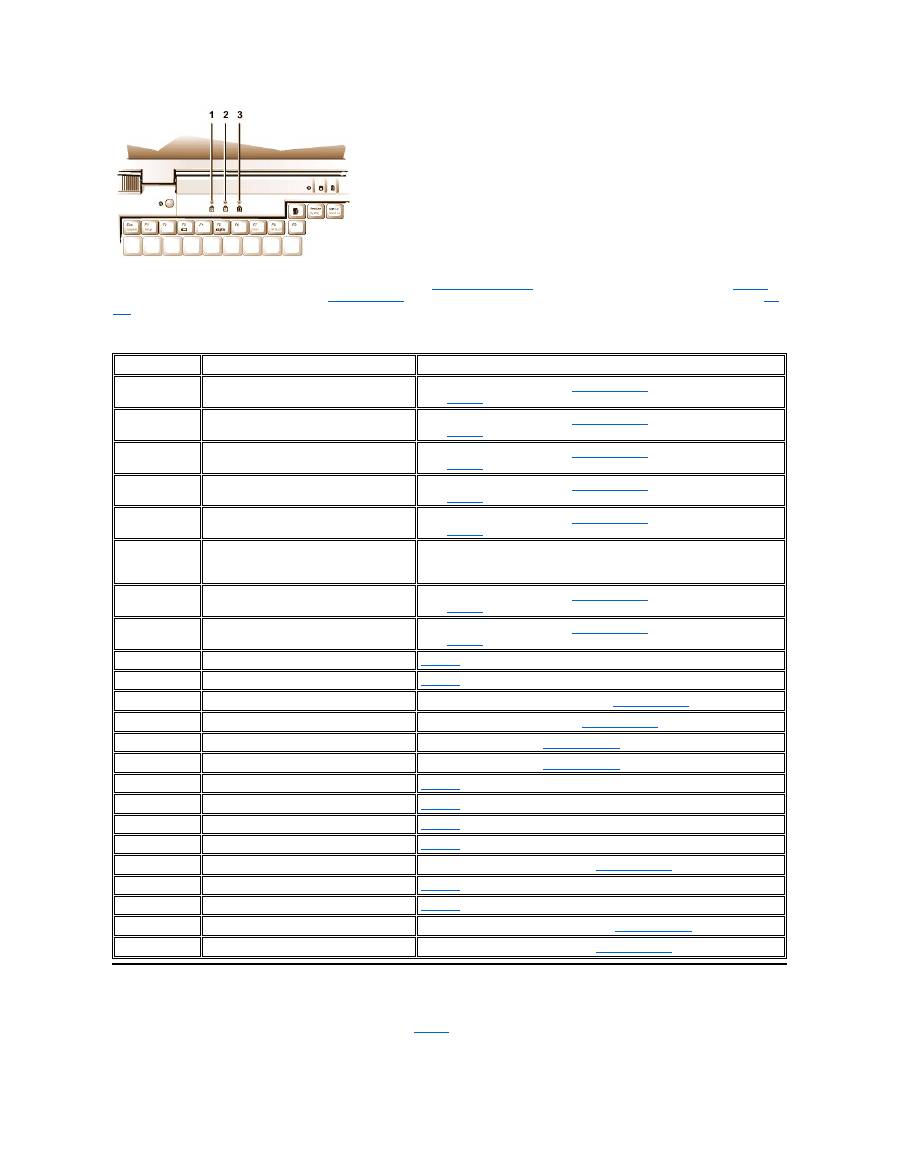
When errors that occur during the boot routine cannot be reported on the display or on an external monitor (if attached), the Num Lock, Caps Lock,
and Scroll Lock indicators (see
Figure 1
) may flash together in a pattern of lights (or
flash code
) that identifies the problem. For example, one
flash, followed by a second flash, and then a burst of three flashes (code 1-1-3) means that the computer was unable to read the data in nonvolatile
random-access memory (NVRAM). This information is important to the Dell support staff if you need to call for technical assistance.
The Num Lock, Caps Lock, and Scroll Lock indicators flash briefly when the computer is turned on. The flash codes, if needed, occur after the boot
routine.
Figure 1. Flash Code Indicators
Memory odd/even logic
failure at address,
read value expecting
value
Memory write/read
failure at address,
read value expecting
value
No boot device
available
The computer cannot find the diskette or
hard-disk drive.
If the diskette drive is your
boot device
, make sure that there is a
bootable diskette in the drive. If the hard-disk drive is your boot
device, make sure that the drive is installed, properly seated, and
partitioned as a boot device.
No boot sector on
hard-disk drive
The operating system may be corrupted.
Reinstall your operating system. See the documentation that came
with your operating system.
No timer tick
interrupt
A chip on the system board may be
malfunctioning.
Run the
System Set
tests in the
Dell Diagnostics
.
Non-system disk or
disk error
The diskette in drive A or your hard-disk
drive does not have a bootable
operating system installed on it.
If you are trying to boot from the diskette, replace it with one that
has a bootable operating system.
Not a boot diskette
There is no operating system on the
diskette.
Boot the computer with a diskette that contains an operating
system.
Optional ROM bad
checksum
The optional ROM apparently failed.
Call Dell
for technical assistance.
Sector not found
The operating system cannot locate a
sector on the diskette or hard-disk drive.
You probably have a bad sector or
corrupted FAT on the diskette or hard-
disk drive.
Run the appropriate utility to check the file structure on the diskette
or hard-disk drive. If a large number of sectors are defective, back
up the data (if possible), and then reformat the diskette or hard-
disk drive.
Seek error
The operating system cannot find a
specific track on the diskette or hard-
disk drive.
If the error is on the diskette drive, try another diskette in the drive.
Shutdown failure
A chip on the system board may be
malfunctioning.
Run the
System Set
tests in the
Dell Diagnostics
.
Time-of-day clock lost
power
Data stored in NVRAM has become
corrupted.
Connect your computer to an electrical outlet to charge the battery.
If the problem persists, try to restore the data. To restore the data,
press <Fn><F1> to
enter the System Setup program
. Then
immediately exit it. If the message reappears,
call Dell
for
technical assistance.
Time-of-day clock
stopped
The reserve battery that supports the
data stored in NVRAM may be dead.
Connect your computer to an electrical outlet to charge the battery.
If the problem persists,
call Dell
for technical assistance.
Time-of-day not set-
please run the System
Setup program
The time or date stored in the System
Setup program does not match the
system clock.
Correct the settings for the
Date
and
Time
options. (For
instructions, see "
System Setup Program
.")
Timer chip counter 2
failed
A chip on the system board may be
malfunctioning.
Run the
System Set
tests in the
Dell Diagnostics
.
Unexpected interrupt
in protected mode
The keyboard controller may be
malfunctioning, or an installed memory
module may be loose.
Run the
System Memory
tests and the
Keyboard Controller
test in the
Dell Diagnostics
.
Warning: Battery is
critically low.
The battery is running out of charge.
Replace the
battery
, or connect the computer to an electrical
outlet. Otherwise, activate
suspend-to-disk
mode or turn off the
computer.
When the computer emits a flash code, write it down on a copy of the
Diagnostics Checklist
and then look up its cause and meaning in
Table 2
. If
you are unable to resolve the problem, use the
Dell Diagnostics
to identify a more serious cause. If you are still unable to resolve the problem,
call
Dell
for technical assistance.
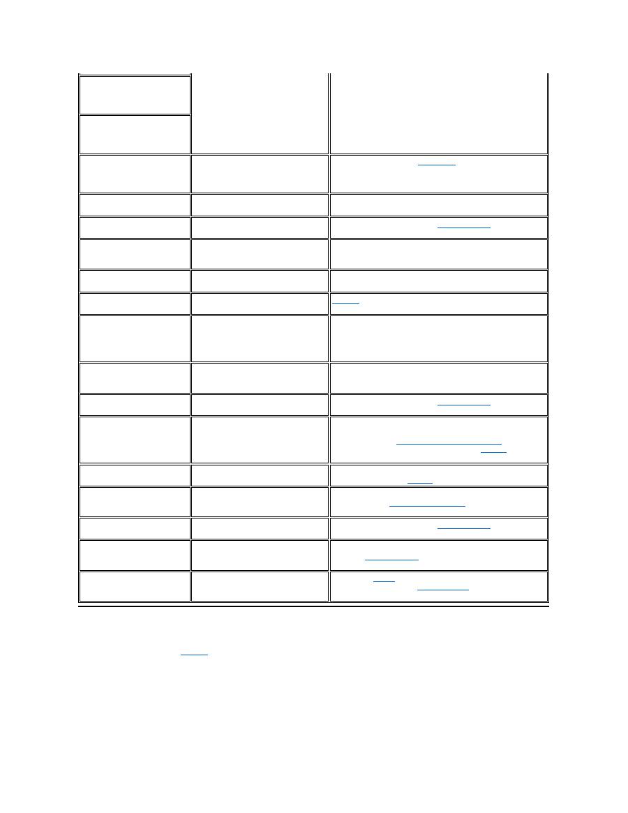
Table 2. Flash Codes and Corrective Actions
Avoiding Interrupt Assignment Conflicts
Problems can arise if two devices attempt to use the same interrupt request (IRQ) line. To avoid this type of conflict, check the documentation for
the default IRQ line setting for each installed device. Then consult
Table 3
to configure the device for one of the available IRQ lines.
1
Num Lock
2
Caps Lock
3
Scroll Lock
Message
Cause
Action
1-1-3
NVRAM write/read failure.
Run the
System Set
tests in the
Dell Diagnostics
. If the program does not
load,
call Dell
for technical assistance.
1-1-4
ROM BIOS checksum failure.
Run the
System Set
tests in the
Dell Diagnostics
. If the program does not
load,
call Dell
for technical assistance.
1-2-1
Programmable interval timer failure.
Run the
System Set
tests in the
Dell Diagnostics
. If the program does not
load,
call Dell
for technical assistance.
1-2-2
DMA initialization failure.
Run the
System Set
tests in the
Dell Diagnostics
. If the program does not
load,
call Dell
for technical assistance.
1-2-3
DMA page register write/read failure.
Run the
System Set
tests in the
Dell Diagnostics
. If the program does not
load,
call Dell
for technical assistance.
1-3-1
through
2-4-4
An installed memory module is not being
properly identified or used.
Make sure that a memory module is installed in one of the memory module
sockets on the system board. The computer will not function unless at least
one memory module is installed.
3-1-1
Slave DMA register failure.
Run the
System Set
tests in the
Dell Diagnostics
. If the program does not
load,
call Dell
for technical assistance.
3-1-2
Master DMA register failure.
Run the
System Set
tests in the
Dell Diagnostics
. If the program does not
load,
call Dell
for technical assistance.
3-1-3
Master interrupt mask register failure.
Call Dell
for technical assistance.
3-1-4
Slave interrupt mask register failure.
Call Dell
for technical assistance.
3-2-4
Keyboard controller test failure.
Run the
Keyboard Controller
test in the
Dell Diagnostics
.
3-3-4
Display memory test failure.
Run the
Video Memory
test in the
Dell Diagnostics
.
3-4-1
Display initialization failure.
Run the
Video
tests in the
Dell Diagnostics
.
3-4-2
Display retrace test failure.
Run the
Video
tests in the
Dell Diagnostics
.
4-2-1
No timer tick.
Call Dell
for technical assistance.
4-2-2
Shutdown failure.
Call Dell
for technical assistance.
4-2-3
Gate A20 failure.
Call Dell
for technical assistance.
4-2-4
Unexpected interrupt in protected mode.
Call Dell
for technical assistance.
4-3-1
Memory failure above address 0FFFFh.
Run the
System Memory
tests in the
Dell Diagnostics
.
4-3-3
Timer chip counter 2 failure.
Call Dell
for technical assistance.
4-3-4
Time-of-day clock stopped.
Call Dell
for technical assistance.
4-4-1
Serial port failure.
Run the
Serial/Infrared Ports
tests in the
Dell Diagnostics
.
5-1-2
No usable memory.
Run the
System Memory
tests in the
Dell Diagnostics
.
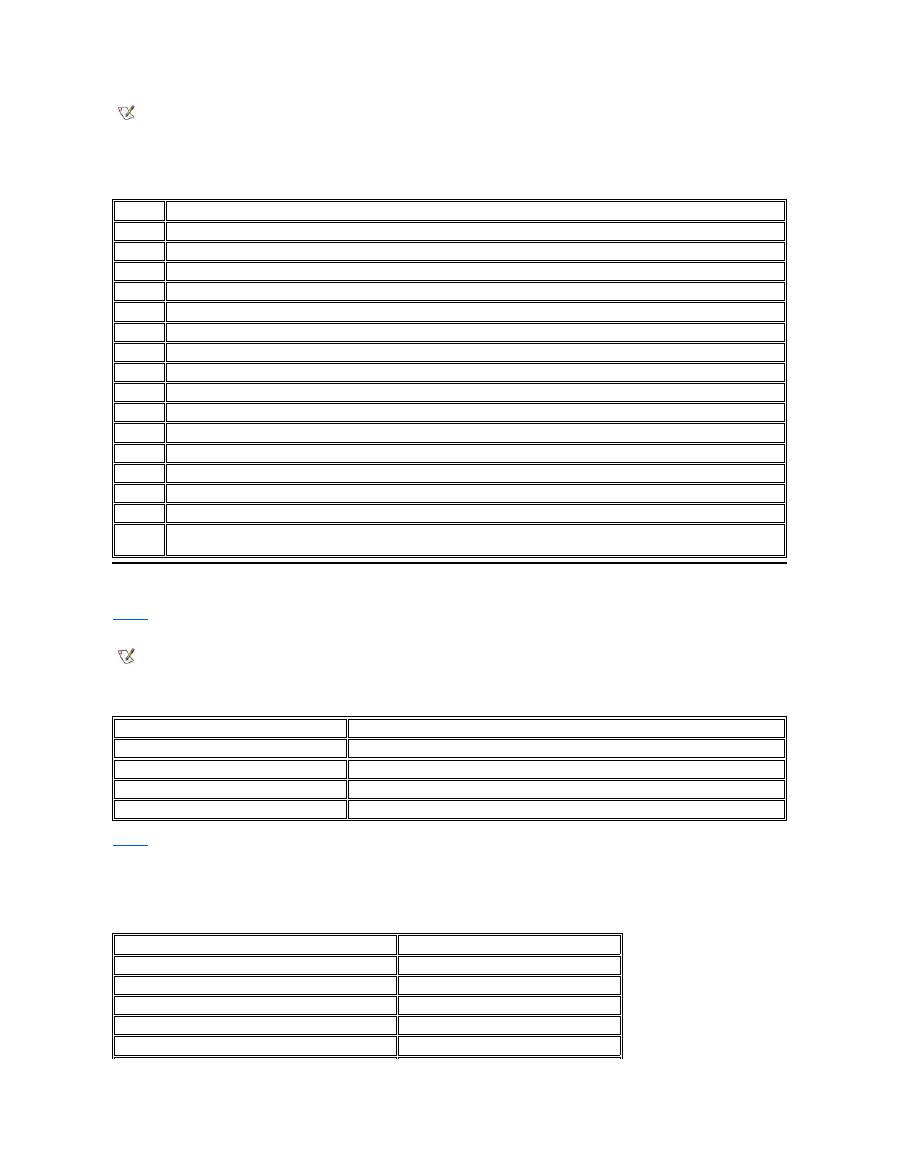
Table 3. IRQ Line Assignments
Memory Allocations
Table 4
provides a map of the conventional memory area. When the microprocessor or a program addresses a location within the conventional
memory range, it is physically addressing a location in main memory.
Table 4. Conventional Memory Map
Table 5
provides a map of the upper memory area. Some of these addresses are dedicated to various system devices, such as the system/video
basic input/output system (BIOS). Others are available for use by expansion cards and/or an expanded memory manager (EMM).
When the microprocessor or a program addresses a location within the upper memory area, it is physically addressing a location within one of
these devices.
Table 5. Upper Memory Map
NOTES: Installed devices cannot share the same COM port address. The default address of your computer's serial port is COM1.
To view IRQ line assignments in the Microsoft
®
Windows
®
95 and Windows 98 operating systems, click the
Start
button, point to
Settings
, and click
Control Panel
. Double-click the
System
icon. Select the
Device Manager
tab, and then double-click
Computer
.
IRQ Line Reserved/Available
IRQ0
Reserved; generated by the system timer
IRQ1
Reserved; generated by the keyboard controller to signal that the keyboard output buffer is full
IRQ2
Reserved; generated internally by the interrupt controller to enable IRQ8 through IRQ15
IRQ3
Available for use by a PC Card unless the integrated serial port or infrared port is configured for COM2 or COM4
IRQ4
Available for use by a PC Card unless the integrated serial port or infrared port is configured for COM1 (the default) or COM3
IRQ5
Available for use by the audio controller
IRQ6
Generated by the diskette drive controller to indicate that the diskette drive requires the attention of the microprocessor
IRQ7
Available for use by a PC Card or audio controller if the parallel port is disabled
IRQ8
Reserved; generated by the system I/O controller's RTC
IRQ9
Reserved
IRQ10
Available for use by a PC Card or audio controller unless the C/Port Family APR or C/Dock Family Expansion Station is attached
IRQ11
Available for use by USB, PC Card, video controller, and audio controller
IRQ12
Reserved; generated by the keyboard controller to indicate that the output buffer of the touch pad or external PS/2 mouse is full
IRQ13
Reserved; generated by the math coprocessor
IRQ14
Reserved; generated by the hard-disk drive to indicate that the drive requires the attention of the microprocessor
IRQ15
Reserved; generated by CD-ROM drive in the external media bay to indicate that the drive requires the attention of the
microprocessor
NOTE: To view memory allocations in Windows 95 and Windows 98, click the
Start
button, point to
Settings
, and click
Control Panel
.
Double-click the
System
icon. Click the
Device Manager
tab, and then double-click
Computer
.
Address Range
Use
0000h-003FFh
Interrupt vector table
00400h-004FFh
BIOS data area
00500h-005FFh
MS-DOS
®
and BASIC work area
00600h-9FBFFh
User memory
Address Range
Use
0009FC00-0009FFFF
PS/2-mouse data area
000A0000-000BFFFF
Video RAM
000C0000-000CBFFF
Video BIOS
000CC000-000CDFFF
PC Card
000F0000-000FFFFF
System BIOS
I/O Memory Map
Table 6
provides a map of memory addresses reserved by the computer for peripheral input/output (I/O) devices. Use the information in Table 6 to
determine if the memory address of an external device (such as a PC Card) conflicts with a memory address reserved by the computer.
Check the documentation of the external I/O device to determine its memory address. If a device's memory address conflicts with a memory
address reserved by the computer, change the address of the device.
Table 6. I/O Memory Map
Back to Contents Page
00100000-03FFFFFF
High memory area
FD000000-FDFFFFFF (approximate; not a fixed location)
Video RAM
FF200000-FF2FFFFF (approximate; not a fixed location)
Video RAM
FFFE0000-FFFFFFFF
BIOS ROM
NOTE: To view I/O addresses in Windows 95 and Windows 98, click the
Start
button,
point to
Settings
, and click
Control Panel
. Double-click the
System
icon. Click the
Device Manager
tab, and then double-click
Computer
.
Address
Device
0000-001F
DMA controller #1
0020-003F
Interrupt controller #1
0040-005F
System timers
0060-0060
Keyboard controller
0061-0061
System speaker
0064-0064
Keyboard controller
0070-007F
RTC and NMI enable
0080-009F
DMA page registers
00A0-00BF
Interrupt controller #2
00C0-00DF
DMA controller #2
00F0-00FF
Math coprocessor
0170-0177
CD-ROM drive controller
01F0-01F7
Hard-disk drive controller
0210-0217
Audio controller
0220-022F
Audio controller
0270-0277
Fast IR
0376-0376
IDE controller
0378-037F
LPT1
0388-038B
Audio controller
03B0-03BB
VGA
03C0-03DF
VGA
03E0-03E1
PC Card controller
03E8-03EF
Fast IR
03F2-03F5;
03F7-03F7
Diskette controller
03F8-03FF
COM1
0530-0537
Audio controller
0778-077B
ECP registers
ECE0-ECFF
USB controller
FFA0-FFAF
PCI-IDE bus registers

Back to Contents Page
Connecting External Devices: Dell™ Latitude™ CS/CS x Portable Computers User's Guide
About the I/O Connectors
You can connect external devices to the input/output (I/O) connectors. The computer's basic input/output system (BIOS) detects the presence of
external devices when you boot (start) or reboot your computer.
Figure 1
shows the I/O connectors on the back of your computer;
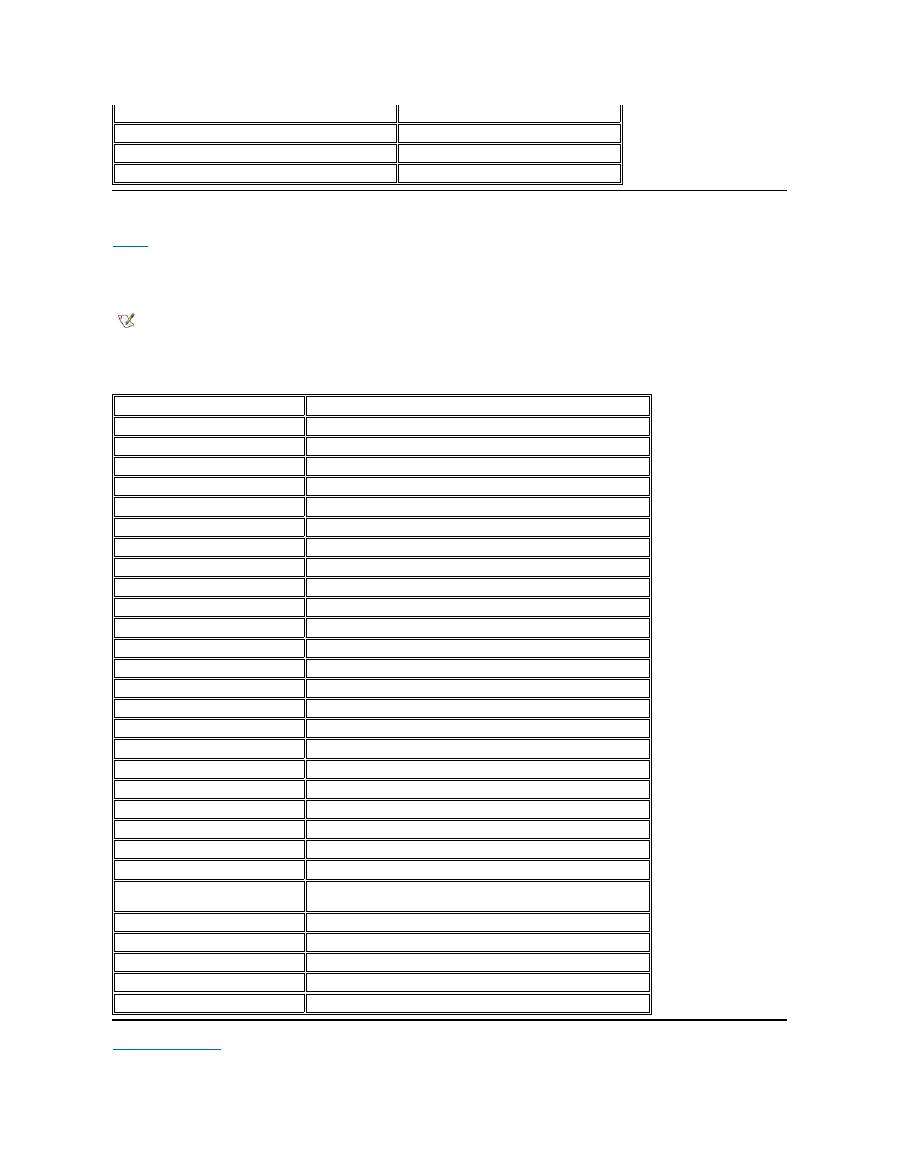
Figure 2
shows
the external media bay and audio connectors on the right side of the computer.
Figure 1. I/O Connectors On the Back of the Computer
Figure 2. I/O Connectors On the Right Side of the Computer
Mouse, Keyboard, and External Numeric Keypad
You can attach a PS/2-compatible device such as a mouse, 101- or 102-key keyboard, or external numeric keypad to the mini-Deutsche Industrie
Norm (DIN) PS/2 connector.
You can also connect these devices to the C/Port Family APR or the C/Dock Family Expansion Station.
About the I/O Connectors
External Monitor
Mouse, Keyboard, and External Numeric Keypad
AC Adapter
USB Devices
Audio Devices
Parallel Devices
External Media Options
Docking Devices
NOTES: Some external devices require you to load software called device drivers into system memory before the devices will work.
These device drivers help your computer recognize the external device and direct its operation. Instructions for installing this software
are usually included in the upgrade kits.
The C/Port Family Advanced Port Replicator (APR) has the same I/O connectors as your computer. In addition, the C/Port APR has a
second Personal System/2 (PS/2) connector, a second Universal Serial Bus (USB) connector, and an Ethernet network connector.
The C/Dock Family Expansion Station has the same I/O connectors as your computer. In addition, the C/Dock Expansion Station has a
second PS/2 connector, a second USB connector, an Ethernet network connector, and a small computer system interface (SCSI)
connector.
1
PS/2 (mini-DIN) connector
2
Parallel connector
3
Video connector
4
AC adapter connector
5
Docking connector
6
USB connector
1
External media bay connector
2
Microphone (MIC IN) jack
3
Speakers and headphones (line-out/speaker-out) jack

Mouse
When you attach a PS/2 mouse to the computer, the touch pad is automatically disabled. If you disconnect the mouse, you must shut down the
computer or enter suspend or standby mode and then resume from it before the touch pad is operational. If you do not do this, the touch pad
resumes operation in standard PS/2 mode, which means that many of the configuration features are disabled.
If you are using a PS/2-compatible mouse that is not made by Microsoft and the mouse does not work properly, reboot the computer. If the mouse
still does not work, install the drivers from the diskette that came with the mouse and reboot the computer.
Keyboard
You can use the computer's keyboard and an external keyboard at the same time. When you attach a keyboard to the computer, the embedded
numeric keypad is automatically disabled.
On an external keyboard, the <Scroll Lock> key acts the same way as the <
Fn> key on the computer’
s keyboard (if the
External Hot Key
option is
enabled in the System Setup program).
External Numeric Keypad
When you attach an external numeric keypad to the computer, the numeric keypad on the computer keyboard is automatically disabled. The
indicators on the integrated keyboard track the operation of an external numeric keypad.
USB Devices
You can attach a USB hub device to the USB connector. The USB hub device can support multiple USB devices (typically low-speed peripherals
such as mice, keyboards, printers, and computer speakers). The C/Port APR Family and the C/Dock Expansion Station Family docking solutions
have two USB connectors.
Parallel Devices
You can attach a parallel device (usually a printer) to the 25-hole parallel connector. You can also connect the diskette drive to the parallel
connector.
The parallel port sends and receives data in parallel format, where eight data bits (one byte) are sent simultaneously over eight separate lines. The
port can be configured as a unidirectional (output-only) port for devices such as a printer or as a bidirectional port for devices such as a network
adapter.
The computer's integrated parallel port is designated as LPT1. The Microsoft
®
Windows
®
95 and Windows 98 operating systems automatically
recognize the parallel device and configure it correctly. The parallel port can also be configured for compatibility with the PS/2 standard.
Connecting a Diskette Drive to the Parallel Connector
You can use the the diskette drive as a second external device if you already have a device connected to the media bay connector. The diskette
drive letter is A, unless a diskette drive is already installed in the external media bay, in which case the drive connected to the parallel connector is
NOTE: If the computer is in suspend (or standby) or suspend-to-disk mode when you attach a mouse, you can use the mouse when the
computer resumes normal operation. However, programs that were already running may need to be restarted to recognize the mouse. If
the computer is not in suspend (or standby) or suspend-to-disk mode when you attach the mouse, you must reboot the computer to use
the mouse.
NOTE: If the computer is in suspend (or standby) mode or suspend-to-disk mode when you attach an external keyboard, the device is
recognized immediately by the computer when it resumes normal operation.
NOTE: If the computer is in suspend (or standby) mode or suspend-to-disk mode when you attach an external numeric keypad, the
device is recognized immediately by the computer when it resumes normal operation.
NOTE: If you are using a USB external keyboard, do not enter the System Setup program by using a keyboard command on an
external keyboard. Instead, press <Fn><F1> on the computer's keyboard.
