Dell LATITUDE D400 – страница 3
Инструкция к Ноутбуку Dell LATITUDE D400
Оглавление
- Dell™ Latitude™ CS/CS Portable Computers User's Guide
- AC Adapter: Dell™ Latitude™ CS/CS x Portable Computers User's Guide
drive B.
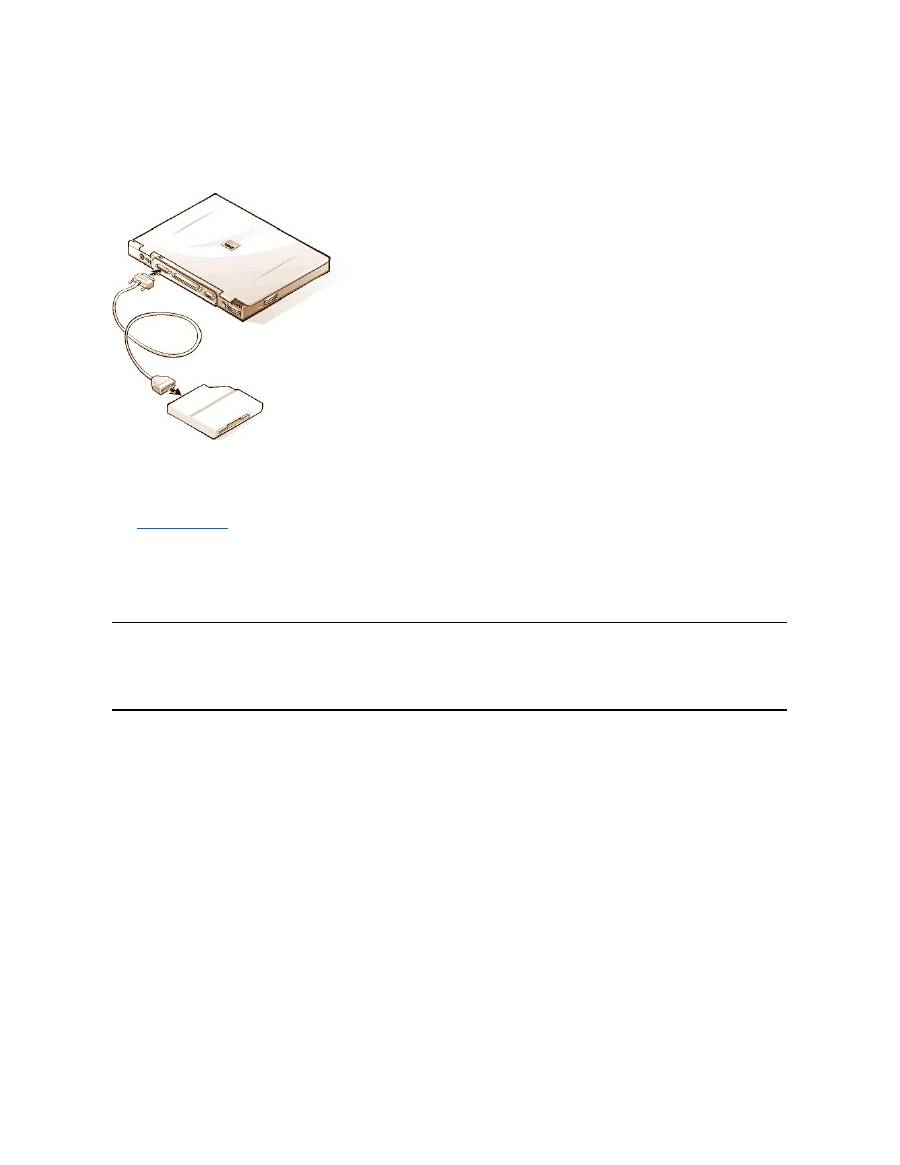
To connect the drive to the parallel connector on the I/O panel, use the optional parallel diskette-drive cable (available from Dell), as shown in
Figure 5.
Figure 5. Connecting a Diskette Drive to the Parallel Connector
NOTICE: When the diskette drive is not being used externally, remove the parallel diskette-drive cable from the parallel connector.
NOTICE: Use the parallel diskette-drive cable only with the diskette drive. Do not try to connect any other device to the computer
with this cable.
If the
Diskette Reconfig
option is set to
Any Time
in the System Setup program, you can connect the diskette drive to the parallel connector while
the computer is turned on.
The drive access indicator does not blink when data is being accessed from the diskette drive connected to the parallel connector.
NOTICE: Protect the diskette drive when it is not in the external media bay. Do not squeeze the drive or place objects on top of it;
doing so could damage the drive motor.
Docking Devices
You can attach your computer to Dell's C/Port Family APR and C/Dock Family Expansion Station docking devices through the docking connector.
For information on docking your computer, see the documentation that came with your docking device.
External Monitor
You can use the 15-hole video connector to attach an external monitor to the computer.
Connecting an External Monitor
To attach an external monitor, perform the following steps.
NOTICE: Do not place the monitor directly on top of your portable computer, even if it is closed. Doing so can crack the computer
case, the display, or both.
1. Make sure that the external monitor is turned off. Set the monitor on a monitor stand, desk top, or other level surface near your computer.
2. Connect the external monitor's video cable to the computer.
Plug the video cable connector into the matching video connector on the back of the computer, as shown in Figure 6. If the video cable
is not permanently attached to the monitor, connect it to the monitor.
Figure 6. Connecting an External Monitor

Be sure to tighten all the screws on the video cable connector(s) to eliminate radio frequency interference (RFI).
3. Connect your external monitor to a grounded electrical outlet.
Plug the three-prong connector on one end of the monitor's power cable into a grounded power strip or some other grounded power
source. If the cable is not permanently attached to the monitor, connect it to the monitor.
You can also connect an external monitor to the C/Port Family APR or the C/Dock Family Expansion Station.
Using an External Monitor
When an external monitor is connected to the computer, the video image automatically appears on the external monitor's screen when you boot
your computer.
To toggle the video image between the display, an external monitor, or both simultaneously, press <Fn><F8> on the keyboard. Press <Scroll
Lock><F8> on an external keyboard if the
External Hot Key
option is enabled in the System Setup program.
If the external monitor is turned off when you boot your computer, the computer still sends the video image to the external monitor, but you will not
see an image on either the computer's display or the external monitor. To see an image, turn on the external monitor or switch the video image to
the computer
’
s display by pressing <Fn><F8> on the keyboard or <Scroll Lock><F8> on an external keyboard if the
External Hot Key
option is
enabled in the System Setup program.
AC Adapter
You can attach the
AC adapter
to the computer by using the AC adapter connector. The AC adapter converts AC power to the DC power required
by the computer.
You can connect the AC adapter with your computer turned either on or off.
The AC adapter works with electrical outlets worldwide. However, power connectors vary among countries. Before using AC power in a foreign
country, you may need to obtain a new power cable designed for use in that country.
Audio Devices
You can connect audio devices such as speakers, microphones, and headphones to the two
audio jacks
, as follows:
l
Connect the audio cable from a microphone to the microphone jack, also called the MIC IN jack.
l
Connect the audio cable
from speakersto the headphones/speakers jack, also called the line-out/speaker-out jack.
If your computer is running the Windows 95 operating system, you can control the sound on your computer through the
Dell Control Center
Speaker
window, the
System Setup
program, and
key combinations
.
External Media Options
You can connect
external media options
such CD-ROM, DVD-ROM, SuperDisk LS-120, and diskette drives to the external media bay connector.
Back to Contents Page
NOTE:
If you are using the Microsoft Windows 98 operating system, you can use an external monitor as an extension of your
display. For more information, see the Windows 98 documentation or "
Dual-Display Mode
."
NOTE: If you are using your external monitor at a resolution greater than the display supports, the simultaneous display feature is
disabled. To use the display, switch to a resolution that the computer supports, or disconnect the external monitor and restart your
computer.
NOTE: The C/Port Family APR also has a headphones/speaker jack. The C/Dock Family Expansion Station has a line
-in/audio-in jack
as well as microphone and headphones/speaker jacks.


Back to Contents Page
Getting Help: Dell™ Latitude™ CS/CS x Portable Computers User's Guide
Back to Contents Page
Help Overview
Contacting Dell

Back to Contents Page
Help Overview: Dell™ Latitude™ CS Portable Computers User's Guide
Technical Assistance
If you need assistance with a technical problem, perform the following steps:
1. Run the Dell Diagnostics as described in "
Running the Dell Diagnostics
."
2. Make a copy of the
Diagnostics Checklist
and fill it out.
3. Use Dell's extensive suite of online services available at Dell's World Wide Web site (
http://www.dell.com
) for help with installation and
troubleshooting procedures.
4. If the preceding steps have not resolved the problem and you need to talk to a Dell technician, call Dell's technical support service.
When prompted by Dell's automated telephone system, enter your Express Service Code to route the call directly to the proper support
personnel. If you do not have an Express Service Code, open the
Dell Accessories
folder, double-click the
Express Service Code
icon, and follow the directions.
For instructions on using the technical support service, refer to "
Technical Support Service
" and "
Before You Call
."
Help Tools
Dell provides a number of tools to assist you. These tools are described in the following sections.
World Wide Web on the Internet
The Internet is your most powerful tool for obtaining information about your computer and other Dell products. Through the Internet, you can access
most of the services described in this section, including AutoTech, TechFax, order status, technical support, and product information.
Everything you need to know about your system is presented on the system support page, including the following tools and information:
l
Technical information
—
Details on every aspect of your system, including hardware specifications.
l
Self-diagnostic tools
—
A system-specific troubleshooting application for resolving many computer-related issues by following interactive
flowcharts.
l
Drivers, files, and utilities
—
The latest drivers and basic input/output system (BIOS) updates to keep your system functioning at its best.
l
Component support
—
Technical information, documentation, and troubleshooting tips for different system components.
l
Online communications center
—
Tool for submitting requests for both technical and nontechnical information on Dell products. Avoid
telephone delays by receiving an e-mail response to your request for information if your computer is not functioning properly or if you have
questions regarding your computer's hardware or operation.
Dell can be accessed electronically using the following addresses:
l
World Wide Web
http://www.dell.com/
Technical Assistance
Product Information
Help Tools
Returning Items for Warranty Repair or Credit
Problems With Your Order
Before You Call
NOTE: Dell's Express Service Code system may not be available in all countries.
NOTE: Some of the following tools are not always available in all locations outside the continental U.S. Please call your local Dell
representative for information on availability.
From Dell's World Wide Web home page (
http://www.dell.com
), click the
Support
icon, and click
Support Your Dell
. Enter your service
tag number (or, if you have one, your Express Service Code) and click
Submit
. If you don't have your service tag number or Express
Service Code available, you can also select support information by system.

http://www.dell.com/ap/
(for Asian/Pacific countries only)
http://www.euro.dell.com
(for Europe only)
l
Anonymous file transfer protocol (FTP)
ftp.dell.com/
Log in as user: anonymous, and use your e-mail address as your password.
l
Electronic Support Service
mobile_support@us.dell.com
apsupport@dell.com
(for Asian/Pacific countries only)
support.euro.dell.com
(for Europe only)
l
Electronic Quote Service
sales@dell.com
apmarketing@dell.com
(for Asian/Pacific countries only)
l
Electronic Information Service
info@dell.com
AutoTech Service
Dell's automated technical support service
—
AutoTech
—
provides recorded answers to the questions most frequently asked by Dell customers.
When you call AutoTech, you use your touch-tone telephone to select the subjects that correspond to your questions. You can even interrupt an
AutoTech session and continue the session later. The code number that the AutoTech service gives you allows you to continue your session where
you ended it.
The AutoTech service is available 24 hours a day, seven days a week. You can also access this service through the technical support service. For
the telephone number to call, refer to "
Contacting Dell
."
TechFax Service
Dell takes full advantage of fax technology to serve you better. Twenty-four hours a day, seven days a week, you can call the Dell TechFax line toll-
free for all kinds of technical information.
Using a touch-tone phone, you can select from a full directory of topics. The technical information you request is sent within minutes to the fax
number you designate. For the TechFax telephone number to call, refer to "
Contacting Dell
."
TechConnect BBS
Use your modem to access Dell's TechConnect bulletin board service (BBS) 24 hours a day, seven days a week. The service is menu-driven and
fully interactive. The protocol parameters for the BBS are 1200 to 19.2K baud, 8 data bits, no parity, 1 stop bit.
Automated Order-Status System
You can call this automated service to check on the status of any Dell products that you have ordered. A recording prompts you for the information
needed to locate and report on your order. For the telephone number to call, refer to "
Contacting Dell
."
Technical Support Service
Dell's industry-leading hardware technical support service is available 24 hours a day, seven days a week, to answer your questions about Dell
hardware.
Our technical support staff pride themselves on their track record: more than 90 percent of all problems and questions are taken care of in just one
toll-free call, usually in less than 10 minutes. When you call, our experts can refer to records kept on your Dell system to better understand your
particular question. Our technical support staff use computer-based diagnostics to provide fast, accurate answers to questions.
To contact Dell's technical support service, first refer to "
Before You Call
" and then call the number for your country as listed in "
Contacting Dell
."
Problems With Your Order
If you have a problem with your order, such as missing parts, wrong parts, or incorrect billing, contact Dell for customer assistance. Have your
invoice or packing slip handy when you call. For the telephone number to call, refer to "
Contacting Dell
."

Product Information
If you need information about additional products available from Dell, or if you would like to place an order, visit Dell's World Wide Web site at
http://www.dell.com
. For the telephone number to call to speak to a sales specialist, refer to "
Contacting Dell
."
Returning Items for Warranty Repair or Credit
Prepare all items being returned, whether for repair or credit, as follows:
1. Call Dell to obtain an authorization number, and write it clearly and prominently on the outside of the box.
For the telephone number to call, refer to "
Contacting Dell
."
2. Include a copy of the invoice and a letter describing the reason for the return.
3. Include a copy of the
Diagnostics Checklist
indicating the tests you have run and any error messages reported by the Dell Diagnostics.
4. Include any accessories that belong with the item(s) being returned (power cables, so ftware diskettes, guides, and so on) if the return is for
credit.
5. Pack the equipment to be returned in the original (or equivalent) packing materials.
You are responsible for paying shipping expenses. You are also responsible for insuring any product returned, and you assume the risk of loss
during shipment to Dell. Collect On Delivery (C.O.D.) packages are not accepted.
Returns that are missing any of the preceding requirements will be refused at our receiving dock and returned to you.
Before You Call
Remember to fill out the
Diagnostics Checklist
. If possible, turn on your system before you
call Dell
for technical assistance and call from a
telephone at or near the computer. You may be asked to type some commands at the keyboard, relay detailed information during operations, or try
other troubleshooting steps possible only at the computer system itself. Make sure the system documentation is available.
Diagnostics Checklist
NOTE: Have your Express Service Code ready when you call. The code helps Dell's automated-support telephone system direct your
call more efficiently.
CAUTION: If you need to remove the computer covers, be sure to first disconnect the computer system's power and modem
cables from all electrical outlets.
Date:
Name:
Address:
Phone number:
Service tag (bar code on the back of the computer):
Express Service Code:
Return Material Authorization Number (if provided by Dell support technician):
Operating system and version:
Peripherals:
Expansion cards:
Are you connected to a network? Yes No
Network, version, and network card:
Programs and versions:

Back to Contents Page
Refer to your operating system documentation to determine the contents of the system
’
s start-up files. If the
computer is connected to a printer, print each file. Otherwise, record the contents of each file before calling Dell.
Error message, beep code, or diagnostic code:
Description of problem and troubleshooting procedures you performed:

Back to Contents Page
Introduction: Dell™ Latitude™ CS/CS x Portable Computers User's Guide
Overview
Dell Latitude CS and CS
x
portable computers are expandable multimedia systems designed around an Intel
®
Mobile Pentium
®
II microprocessor
or an Intel Mobile Pentium III microprocessor, both with Peripheral Component Interconnect (PCI) technology. This section describes the major
hardware and software features of your computer.
Figure 1
,
Figure 2
, and
Figure 3
show the front/right, back/left, and bottom views of the
computer.
Figure 4
identifies the system status and keyboard status indicators.
Figure 1. Front/Right View of the Computer
Figure 2. Back/Left View of the Computer
Overview
Available Options
Features
Getting Help
1
Display
2
System status indicators (3)
3
Integrated microphone
4
Audio jacks (2)
5
PC Card slots (2)
6
External media bay
7
Media bay cable (attached to media bay connector on
computer)
8
Speaker
9
Hard-disk drive bay
10
Display latch
11
Touch pad buttons
12
Touch pad
13
Keyboard
14
Power button
15
Keyboard status indicators (3)
1
Air vent
2
Security
cable slot
3
Air vent
4
AC adapter
connector
5
Video
connector
6
Docking
connector
7
Parallel
connector
8
USB
connector
9
PS/2
connector
10
Integrated
microphone
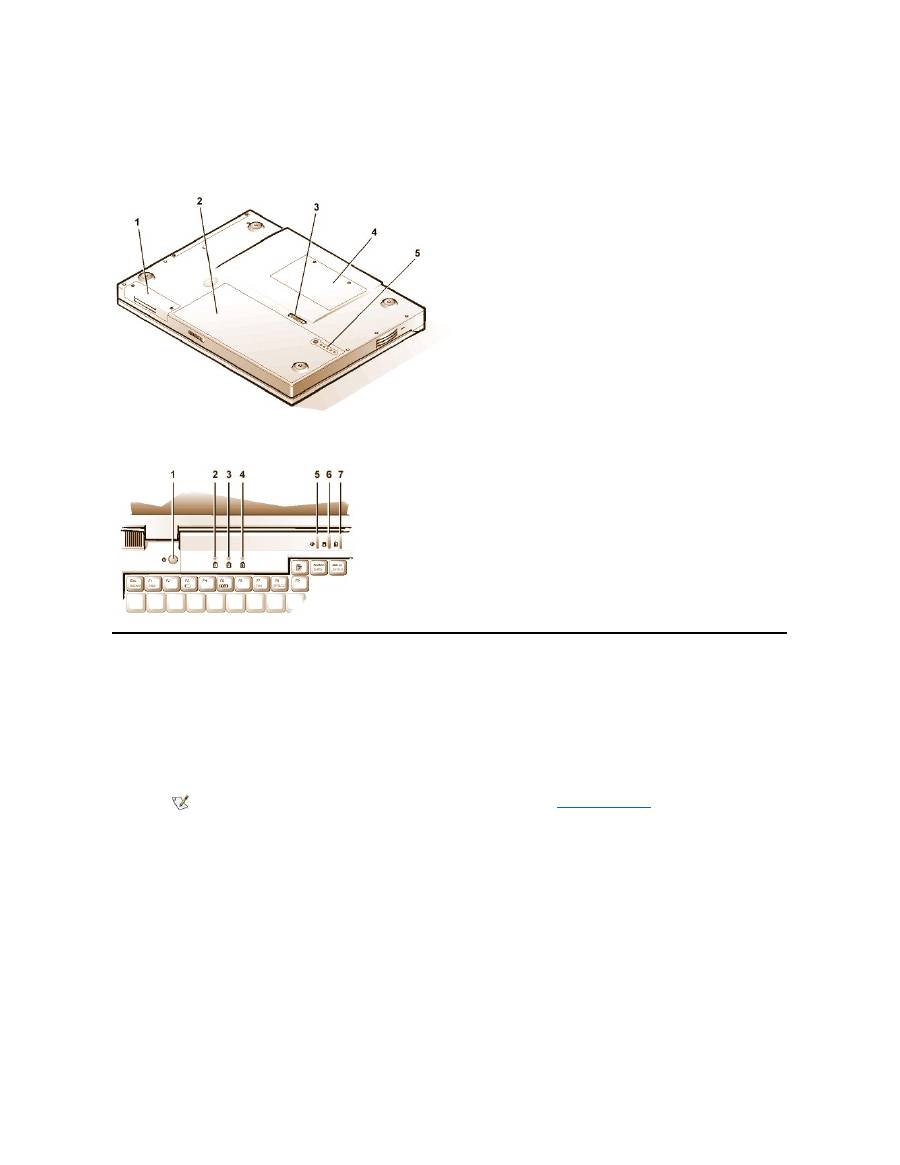
Figure 3. Bottom View of the Computer
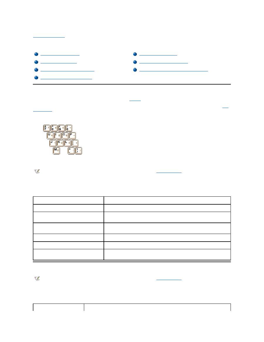
Figure 4. Indicator Panel Features
Features
Your Dell computer provides the following features:
l
Full multimedia capability through the following standard features:
¡
A 13.3-inch extended graphics array (XGA), 1024 x 768 thin film transistor (TFT) active-matrix color display
¡
An external media bay that supports storage devices such as a DVD-ROM, CD-ROM, diskette, SuperDisk LS-120, or second hard-
disk drive
¡
256-bit hardware-accelerated video support, with 4 megabytes (MB) of video memory
¡
Accelerated graphics port (AGP) architecture that increases the computer's video performance
¡
Support for a zoomed video (ZV) PC Card in the top PC Card slot
¡
Two audio jacks for connecting a microphone and external stereo speakers or headphones
¡
Integrated microphone and speaker
¡
Software wavetable support and Sound Blaster software-emulation capability
l
System memory consisting of synchronous dynamic random-access memory (SDRAM) small outline, dual-inline memory modules
(SODIMMs). Factory
-installed memory can range from 64 MB to a system maximum of 320 MB. Depending on the memory already installed,
you may be able to increase memory by installing a 32-, 64-, or 128-MB SDRAM SODIMM in the memory upgrade socket. The achievable
memory total for your computer depends on the computer's original memory configuration.
l
Two power conservation modes
—
suspend (or standby) mode
and
suspend-to-disk mode
—
that help you conserve battery power. If the
11
System
status
indicators
1
Hard-disk drive bay
2
Battery
3
Battery latch
4
Memory module cover
5
Battery charge gauge
1
Power button
2
Num Lock indicator
3
Caps Lock indicator
4
Scroll Lock indicator
5
Power indicator
6
Drive access indicator
7
Battery status indicator
NOTE: For information on installing devices in the external media bay, see "
External Media Bay
."

batteries run out of power, suspend-to-disk mode prevents data loss by copying all system data to the hard-disk drive and turning off the
computer.
l
Connectors for two 3.3-volt (V) or 5-V PC Cards. The upper PC Card slot supports ZV PC Cards.
l
Hardware and software support for the Dell Latitude C/Port Family Advanced Port Replicator (APR) and the Dell Latitude C/Dock Family
Expansion Station.
l
A touch-pad pointing device positioned for both left- and right-handed users. The left and right touch-pad buttons mimic mouse buttons; you
can also perform many pointing functions by tapping the touch pad itself. Click-and-drag buttonless functions are supported.
l
A lithium ion battery in the battery bay. The Dell ExpressCharge
™
technology charges a single battery in approximately 1 hour (when the
computer is off or in suspend [or standby] mode).
l
A high-performance parallel port and a multipurpose Personal System/2 (PS/2) connector for attaching external devices, a monitor connector
for attaching an external monitor to your computer, and a Universal Serial Bus (USB) connector that supports stand-alone and hub devices.
l
An automatic thermal management system that uses a variable-speed fan and microprocessor speed changes to keep the system running
at the optimum temperature.
The following software is included with your Dell computer:
l
The Microsoft
®
Windows
®
95, Windows 98, or Windows NT
®
4.0 or later operating system is installed on your hard-disk drive. For more
information, see your operating system documentation.
l
The
System Setup program
lets you view and change the system configuration.
l
The Program Diskette Maker allows you to create program diskette sets of software that Dell installed on your computer's hard-disk drive.
l
Dell Diagnostics
for evaluating the computer's components and devices.
Available Options
Dell offers the following devices and upgrade options:
l
C/Port Family APRs and C/Dock Family Expansion Stations
l
Additional batteries
l
External keyboards and keypads
l
External monitors
l
External pointing devices
l
External speakers, headphones, and microphones
l
Printers
l
Dell Latitude C-Family storage devices such as hard-disk drives, additional hard-disk drives for the external media bay, CD-ROM
drives, 4x
DVD-ROM drives, and SuperDisk LS-120 drives
l
AC adapter
l
PC Cards
l
32-, 64-, and 128-MB memory upgrade modules
l
Carrying cases
NOTE: The PC Card controller supports the CardBus standard for 32-bit data transfer on the PC Card.
NOTE: The batteries are designed to work only with Dell Latitude CS/CSx portable computers. Do not use the batteries with other
computers, and do not use batteries from other computers with the Dell Latitude CS/CSx.
CAUTION: Do not puncture or incinerate the battery. When your battery no longer holds a charge, call your local waste
disposal agency or environmental agency for advice on disposing of the computer's lithium ion battery. The lithium ion
technology used in the battery is significantly less hazardous to the environment than the lithium metal technology used in
some other batteries (such as watch batteries)
.
NOTE: If Dell did not install an operating system on your hard-disk drive, the drivers, system utilities, and diagnostics are available
separately from Dell. To order them, see "
Getting Help
" for the appropriate telephone number in your location.

Instructions for connecting or installing these options are included in the upgrade kit you receive from Dell. For more information on options
available for your system, visit the Dell World Wide Web site at
http://www.dell.com
.
Getting Help
If at any time you don't understand a procedure described in this guide, or if your computer does not perform as expected, Dell provides a number
of tools to help you. For more information on these help tools, see "
Getting Help
."
Back to Contents Page
Back to Contents Page
Keyboard: Dell™ Latitude™ CS/CS x Portable Computers User's Guide
Embedded Numeric Keypad
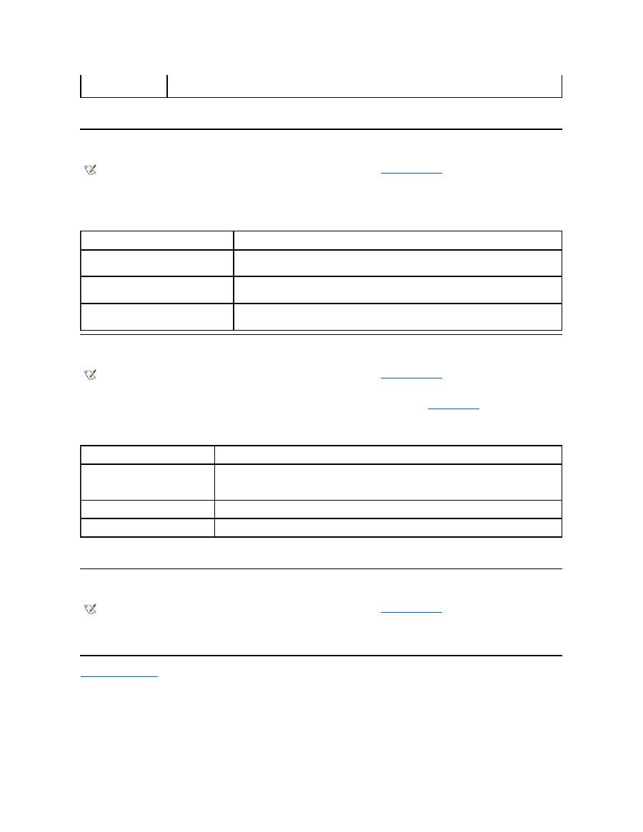
As you work, you may want to use the embedded numeric keypad (see
Figure 1
) to enter numbers in spreadsheet or financial programs. The
embedded numeric keypad shares some of the keys on your computer's keyboard. On these keys, the number and symbol characters of the
numeric keypad appear in blue to the right of the main keypad characters. To activate the embedded numeric keypad, press <Num Lk> (the
Num
Lock indicator
lights up).
Figure 1. Embedded Numeric Keypad
Some key combinations can be used whether or not the keypad is activated.
Use the numeric keypad combinations in Table 1 to enable and disable several numeric keypad functions.
Table 1. Embedded Numeric Keypad Key Combinations
Display Key Combinations
Use the key combinations in Table 2 to adjust the computer's display.
Table 2. Display Key Combinations
Embedded Numeric Keypad
Speaker Key Combinations
Display Key Combinations
System Function Key Combinations
Power Conservation Key Combinations
CD-ROM and DVD-ROM Drive Key Combinations
Processing Speed Key Combinations
NOTE: On an external keyboard, use <Scroll Lock> with the appropriate keys if the
External Hot Key
option is enabled in the System
Setup program.
When Keypad Is On
Function
<Num Lk>
Toggles the embedded numeric keypad off
<Fn><
key
>
Temporarily disables the embedded numeric keypad; enables the
lowercase characters/functions of the keyboard
<Fn><Shift><
key
>
Temporarily disables the embedded numeric keypad; enables the
uppercase characters/functions of the keyboard
When Keypad Is Off
Function
<Num Lk>
Toggles the embedded numeric keypad on
<Fn><Shift><
number key
>
Temporarily enables a number or symbol key in the embedded
numeric keypad
NOTE: On an external keyboard, use <Scroll Lock> with the appropriate keys if the
External Hot Key
option is enabled in the System
Setup program.
Key Combinations
Function

* This key combination may not be supported by future operating systems.
Power Conservation Key Combinations
Use the key combinations in Table 3 to activate or turn off the computer's power conservation features.
Table 3. Power Conservation Key Combinations
* This key combination may not be supported by future operating systems.
Processing Speed Key Combinations
Use the key combinations in Table 4 to change the computer's processing speed.
Table 4. Processing Speed Key Combinations
<Fn> + down arrow
Incrementally decreases brightness.
<Fn> + up arrow
Incrementally increases brightness.
<Fn> + right arrow
Has no effect on your computer.
Decreases contrast on passive-matrix displays; has no effect on active-matrix
displays.
<Fn> + left arrow
Has no effect on your computer.
Increases contrast on passive-matrix displays; has no effect on active-matrix
displays.
<Fn><F5> *
Toggles the computer's display between regular video mode and reverse video mode
(white on black). This key combination works only if the computer is in text mode; it has no
effect if the computer is running a graphical operating system or application program.
<Fn><F7>
Toggles the computer
’
s display between expanded video mode and regular video mode.
<Fn><F8>
Switches the video image to the next display in the following sequence: the display, an
external monitor, or both displays simultaneously.
<Fn><d>*
Turns off the display.
NOTES: Contrast cannot be changed on an active-matrix (thin film transistor [TFT]) display, such as the display in your computer.
To use key combinations on an external keyboard, enable the
External Hot Key
option in the System Setup program and use <Scroll
Lock> instead of <Fn>.
NOTE: On an external keyboard, use <Scroll Lock> with the appropriate keys if the
External Hot Key
option is enabled in the System
Setup program.
Key Combinations
Function
<Fn><d>*
Turns off the display
<Fn><h>*
Turns off the hard-disk drive
<Fn><Esc>*
Activates suspend or standby mode
<Fn><a> or
<Fn><q> on French
keyboards
Activates suspend-to-disk mode
NOTE: On an external keyboard, use <Scroll Lock> with the appropriate keys if the
External Hot Key
option is enabled in the System
Setup program.
<Fn><\> *
Switches between the microprocessor's maximum speed and a slower
compatibility speed
* This key combination may not be supported by future operating systems.
Speaker Key Combinations
Use the key combinations in Table 5 to adjust the computer's speaker volume and to enable and disable the speakers.
Table 5. Speaker Key Combinations
System Function Key Combinations
Use the key combinations in Table 6 to access MS-DOS, open the System Setup program, and open the
Battery Status
screen of the System
Setup program.
Table 6. System Function Key Combinations
* This key combination may not be supported by future operating systems.
CD-ROM and DVD-ROM Drive Key Combinations
To eject the CD-ROM or DVD-ROM tray, press <Fn><F10>.
Back to Contents Page
<Ctrl><\>
In full MS-DOS
®
mode or in a full-screen DOS box, switches between the
microprocessor
’
s maximum speed and a slower compatibility speed
NOTE: On an external keyboard, use <Scroll Lock> with the appropriate keys if the
External Hot Key
option is enabled in the System
Setup program.
Key Combinations
Function
<Fn><Page Up>
Increases the volume of the integrated speaker and the
external speakers, if attached
<Fn><Page Dn>
Decreases the volume of the integrated speaker and the
external speakers, if attached
<Fn><End>
Enables and disables the integrated speaker and the
external speakers, if attached
NOTE: On an external keyboard, use <Scroll Lock> with the appropriate keys if the
External Hot Key
option is enabled in the System
Setup program.
Key Combinations
Function
<Ctrl><Alt><Del>
Restarts (reboots) the computer in MS-DOS mode. In the Microsoft
®
Windows
®
95, Windows 98, and Windows NT
®
operating systems, click
the
Start
button and click
Shut Down
.
<Fn><F1>*
Opens the System Setup program.
<Fn><F3>*
Opens the
Battery Status
screen of the System Setup program.
NOTE: On an external keyboard, use <Scroll Lock> with the appropriate keys if the
External Hot Key
option is enabled in the System
Setup program.

Back to Contents Page
External Media Bay: Dell™ Latitude™ CS/CS x Portable Computers User's Guide
Using the External Media Bay
You can use the external media bay (see
Figure 1
) for the diskette drive that comes with your system. Alternatively, you can install an optional
device (such as a CD-ROM, DVD-ROM, SuperDisk LS-120, or second hard-disk drive) in the bay.
To install a device in the external media bay, perform the following steps:
1.
If your computer is running the Dell-installed Microsoft
®
Windows NT
®
operating system with Softex Docking Services, or if it is running
the Dell-installed Microsoft Windows
®
95 or Windows 98 operating system with Softex Bay Manager:
Right-click the Softex icon (the icon
looks like a tiny open portable computer) in the system tray at the bottom right on your display, and select either
Remove or Swap Devices
or
Insert Bay Devices
.
If your computer is not running one of the Softex programs: S
ave your work, close all open files and application programs, and turn off the
computer.
NOTICE: When a device is not inside the external media bay, it is fragile and must be handled carefully to avoid damage. Do not
press down on it or place a heavy object on top of it. Place the device in a travel case to keep it free of dust and liquids. Store the
device in a safe place.
2. If the external media bay contains a device, remove the media bay cable from the back of the bay. Then remove the device by sliding the
release latch on the bottom of the bay to the release position, holding it there, and pulling the device out of the bay.
3. Slide the new device firmly into the external media bay.
You should hear a click when the device is fully seated.
4. Connect the media bay cable.
Position the larger of the cable connectors with its shiny metal lip down, and connect it firmly to the back of the device through the slot in the
back of the bay. Make sure that the securing clips are fully engaged and the connector is fully seated. Make sure that the other end of the
cable is connected to the media bay connector on the right-hand side of the computer (see Figure 1).
Figure 1. External Media Bay
5.
If your computer is running Softex Docking Services or Softex Bay Manager: Click
OK
at the
Softex Docking Services
or
Softex Bay
Manager
screen. Click
OK
at the
Device Removal
screen (if it appears), and then click
OK
at the
Device Configured
screen.
If you turned off the computer in step 1: Press the power button to turn the computer back on.
Using the External Media Bay
Setting Up a Second Hard-Disk Drive
NOTE: If desired, you can use the media bay cable to connect a device directly to the external media bay connector, without using the
external media bay.
NOTE: For the latest information on Softex Docking Services software, see
http://www.dell.com/products/notebook/latitude/NT40.htm
.

Setting Up a Second Hard-Disk Drive
The first time you install a second hard-disk drive in the external media bay, you must format that drive. For instructions, see the documentation that
came with the device.
Back to Contents Page

Back to Contents Page
Media Options: Dell™ Latitude™ CS/CS x Portable Computers User's Guide
Back to Contents Page
External Media Bay
CD-ROM and DVD-ROM Drives
Diskette Drive

Back to Contents Page
PC Cards: Dell™ Latitude™ CS/CS x Portable Computers User's Guide
About PC Cards
The computer provides two slots in which you can install PC Cards that comply with Release 2.01 of the Personal Computer Memory Card
International Association (PCMCIA) standard and Release 4.2 of the Japanese Electronic Industry Development Association (JEIDA) standard.
The computer supports type I, type II, and type III PC Cards, such as modems, local area network (LAN) cards, wireless LAN cards, and small
computer system interface (SCSI) cards. Also supported are such memory devices as static random-access memory (SRAM) cards that emulate
diskettes, random
-access memory (RAM) cards, and one-time programmable (OTP) ROM cards, and advanced technology attachment (ATA)
cards that emulate integrated drive electronics (IDE) hard-disk drives.
If you are using the Microsoft
®
Windows
®
95 or Windows 98 operating system, you can use a zoomed video (ZV) PC Card, such as a hardware
Moving Picture Experts Group (MPEG) decoder. ZV cards must be used only in the upper PC Card slot. (The Microsoft Windows NT
®
4.0
operating system does not support ZV.)
NOTICE: Take extra precautions if you use extended PC Cards in your computer. Extended cards are longer versions of standard
PC Cards. They fit into, and operate correctly with, your computer. However, they extend beyond the edge of the computer when
installed. If something strikes the exposed end of an installed card, your system board can be damaged. Because of space
considerations, you may have trouble using two PC Cards in your computer if one of them is an extended card. It may be easier to
use an extended card if you install it in the upper PC Card slot. Always remove an extended PC Card before you pack the computer
in its carrying case.
You can use the following PC Card combinations in the PC Card slots:
l
A single type I or type II card (using either the upper or lower PC Card slot)
l
A single type III card (using the lower
PC Card slot only)
l
One type I card and one type II card (using either slot)
l
Two type I cards or two type II cards
Installing PC Cards
PC Cards are generally marked with a symbol, such as a triangle or an arrow, to indicate which end should be inserted into the slot. The cards are
keyed to prevent incorrect insertion. If card orientation is not clear, see the documentation that came with the card.
You do not need to turn off your computer or exit suspend or standby mode before you install a PC Card. To install a PC Card (see Figure 1),
perform the following steps.
Figure 1. Installing a PC Card
About PC Cards
Removing PC Cards
Installing PC Cards
Configuring PC Cards
NOTES: A PC Card is not a boot device.
The "type" of a card refers to its thickness, not its functionality.
Your computer recognizes most I/O cards and automatically loads the device driver associated with that card.
Note: Use a ZV PC Card in the upper slot only.
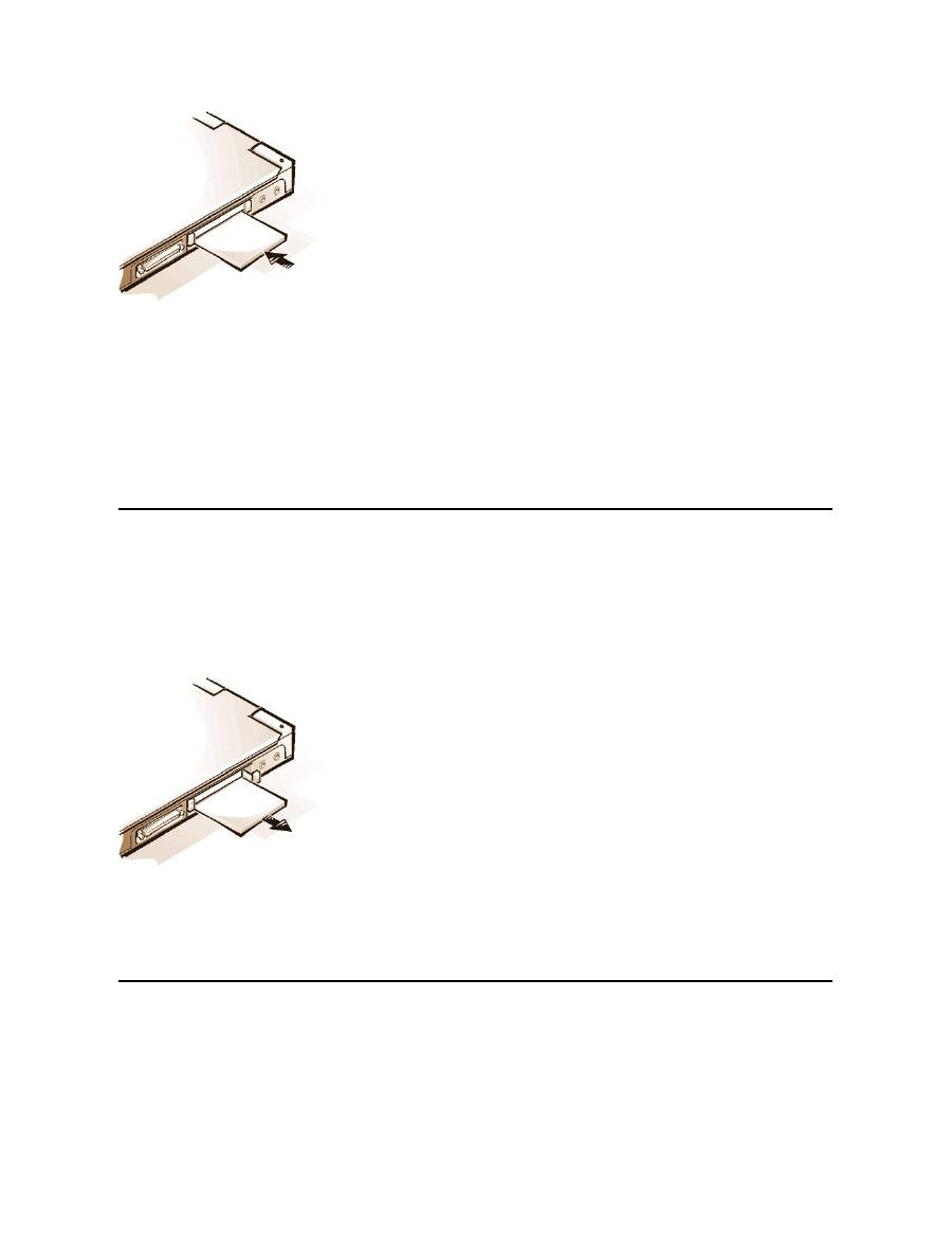
1.
If necessary, remove the blank from the PC Card slot you intend to use. Press the eject button once to pop the button out, press it again to
eject the blank partway, and then pull the blank out.
2.
Make sure that the eject button is pressed all the way in. Hold the card with its orientation symbol pointing into the slot and the top side of the
card facing up.
3.
Insert the card into the slot and press in firmly until the card is completely seated in the internal PC Card connector.
4.
If you encounter too much resistance when inserting it, do not force the card. Check the card's orientation and try again.
PC Card Blanks
Save the blank to use whenever you do not have a PC Card installed. The blank protects the PC Card slot from dust and other particles.
Removing PC Cards
NOTICE: If you are using Windows 95 or Windows 98, use the PC Card configuration utility on the taskbar to select and stop a card
before you remove it. If you do not remove the card in the configuration utility, you could lose data from open application programs.
To remove a PC Card (see Figure 2), perform the following steps.
Figure 2. Removing a PC Card
1.
Press the PC Card eject button once to pop the button out, and then press the button in again to eject the card partway. (The button may or
may not pop out again when you eject the card.)
2.
Gently remove the card.
To protect the PC Card slots, install a blank if you are not going to use the slots.
Configuring PC Cards
The PC Card configuration utility performs the following functions:
l
Notifies you whenever a PC Card is inserted and tells you how the card is configured
l
Automatically loads the proper device driver if it is available on the hard-disk drive
l
If drivers are not available on the hard-disk drive, prompts you to install them by using the device driver diskette that came with the card
