Dell Inspiron 14z N411z – страница 5
Инструкция к Ноутбуку Dell Inspiron 14z N411z

3
Align the four captive screws on the heat sink with the screw holes on the
system board and tighten the screws in sequential order as indicated on the
heat sink.
4
Follow the instructions from step 2 to step 9 in "Replacing the System
Board" on page 75.
5
Replace the wireless mini-card. See "Replacing the Mini-Card" on page 42.
6
Replace the thermal fan. See "Replacing the Thermal Fan" on page 70.
7
Replace the display assembly. See "Replacing the Display Assembly" on
page 47.
8
Replace the memory module(s). See "Replacing the Memory Module(s)"
on page 28.
9
Replace the palm-rest assembly. See "Replacing the Palm-Rest Assembly"
on page 38.
10
Replace the keyboard. See "Replacing the Keyboard" on page 33.
11
Replace the hard-drive assembly. See "Replacing the Hard-Drive Assembly"
on page 21.
12
Follow the instructions from step 5 to step 6 in "Replacing the Optical
Drive" on page 25.
13
Replace the module cover. See "Replacing the Module Cover" on page 16.
14
Replace the battery. See "Replacing the Battery" on page 14.
CAUTION: Before turning on the computer, replace all screws and ensure that no
stray screws remain inside the computer. Failure to do so may result in damage to
the computer.
Heat-Sink Assembly 81

82 Heat-Sink Assembly

18
Media-Card Reader Board
WARNING: Before working inside your computer, read the safety information
that shipped with your computer. For additional safety best practices information,
see the Regulatory Compliance Homepage at dell.com/regulatory_compliance.
CAUTION: Only a certified service technician should perform repairs on your
computer. Damage due to servicing that is not authorized by Dell is not covered by
your warranty.
CAUTION: To avoid electrostatic discharge, ground yourself by using a wrist
grounding strap or by periodically touching an unpainted metal surface (such as a
connector on your computer).
CAUTION: To help prevent damage to the system board, remove the main battery
(see "Removing the Battery" on page 13) before working inside the computer.
Removing the Media-Card Reader Board
1
Follow the instructions in "Before You Begin" on page 9.
2
Remove the battery. See "Removing the Battery" on page 13.
3
Remove the module cover. See "Removing the Module Cover" on page 15.
4
Follow the instructions from step 4 to step 5 in "Removing the Optical
Drive" on page 23.
5
Remove the keyboard. See "Removing the Keyboard" on page 31.
6
Remove the palm-rest assembly. See "Removing the Palm-Rest Assembly"
on page 35.
7
Lift the securing latches and disconnect the media-card reader board cable
from the connectors on the system board and the media-card reader board.
8
Remove the screw that secures the media-card reader board to the
computer base.
Media-Card Reader Board 83
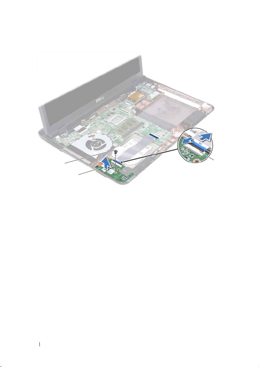
1 screw 2 media-card reader board
3 media-card reader board cable connectors (2)
9
Lift the media-card reader board away from the computer base.
Replacing the Media-Card Reader Board
1
Follow the instructions in "Before You Begin" on page 9.
2
Align the media-card reader board with the alignment poles on the
computer base.
3
Replace the screw that secures the media-card reader board to the
computer base.
4
Slide the cable into the connectors on the system board and the media-
card reader board, and then press down the securing latches.
5
Replace the palm-rest assembly. See "Replacing the Palm-Rest Assembly"
on page 38.
84 Media-Card Reader Board
3
1
2

6
Replace the keyboard. See "Replacing the Keyboard" on page 33.
7
Follow the instructions from step 5 to step 6 in "Replacing the Optical
Drive" on page 25.
8
Replace the module cover. See "Replacing the Module Cover" on page 16.
9
Replace the battery. See "Replacing the Battery" on page 14.
CAUTION: Before turning on the computer, replace all screws and ensure that no
stray screws remain inside the computer. Failure to do so may result in damage to
the computer.
Media-Card Reader Board 85

86 Media-Card Reader Board

19
Speakers
WARNING: Before working inside your computer, read the safety information
that shipped with your computer. For additional safety best practices information,
see the Regulatory Compliance Homepage at dell.com/regulatory_compliance.
CAUTION: Only a certified service technician should perform repairs on your
computer. Damage due to servicing that is not authorized by Dell is not covered by
your warranty.
CAUTION: To avoid electrostatic discharge, ground yourself by using a wrist
grounding strap or by periodically touching an unpainted metal surface (such as a
connector on your computer).
CAUTION: To help prevent damage to the system board, remove the main battery
(see "Removing the Battery" on page 13) before working inside the computer.
Removing the Speakers
1
Follow the instructions in "Before You Begin" on page 9.
2
Remove the battery. See "Removing the Battery" on page 13.
3
Remove the module cover. See "Removing the Module Cover" on page 15.
4
Follow the instructions from step 4 to step 5 in "Removing the Optical
Drive" on page 23.
5
Remove the hard-drive assembly. See "Removing the Hard-Drive
Assembly" on page 19.
6
Follow the instructions in step 5 to step 17 in "Removing the System
Board" on page 73.
7
Remove the media-card reader board. See "Removing the Media-Card
Reader Board" on page 83.
8
Note the speakers cable routing and remove the cable from the routing
guides.
9
Remove the two screws that secure the speakers to the computer base.
Speakers 87
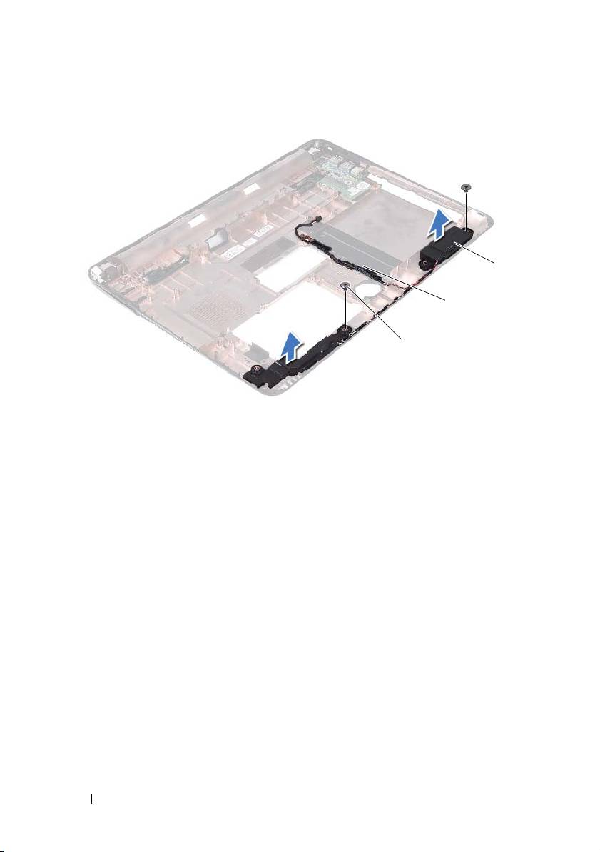
1 screws (2) 2 speaker cable
3 speakers (2)
10
Lift the speakers, along with the speaker cable, off the computer base.
Replacing the Speakers
1
Follow the instructions in "Before You Begin" on page 9.
2
Route the speaker cables through the routing guides.
3
Align the speakers with the alignment posts on the computer base and
place the speakers in the computer base.
4
Replace the two screws that secure the speakers to the computer base.
5
Replace the media-card reader board. See "Replacing the Media-Card
Reader Board" on page 84.
6
Replace the hard-drive assembly. See "Replacing the Hard-Drive Assembly"
on page 21.
88 Speakers
3
2
1

7
Follow the instructions in step 3 to step 16 in "Replacing the System
Board" on page 75.
8
Follow the instructions from step 5 to step 6 in "Replacing the Optical
Drive" on page 25.
9
Replace the module cover. See "Replacing the Module Cover" on page 16.
10
Replace the battery. See "Replacing the Battery" on page 14.
CAUTION: Before turning on the computer, replace all screws and ensure that no
stray screws remain inside the computer. Failure to do so may result in damage to
the computer.
Speakers 89

90 Speakers

20
System Setup
Use the system setup to:
• Change the system configuration information after you add, change, or
remove any hardware in your computer
• Set or change a user-selectable option such as the user password
• Read the current amount of memory or set the type of hard drive installed
NOTE: Before you change system setup, it is recommended that you note the
system-setup screen information for future reference.
Entering System Setup
1
Turn on (or restart) your computer.
2
When the DELL logo is displayed, watch for the F2 prompt to appear and
then press <F2> immediately.
NOTE: The F2 prompt indicates that the keyboard has initialized. This prompt
can appear very quickly, so you must watch for it, and then press <F2>. If you
press <F2> before the F2 prompt, this keystroke is lost. If you wait too long and
the operating system logo appears, continue to wait until you see the
Microsoft Windows desktop. Then, shut down your computer. See "Turning Off
Your Computer" on page 9 and try again.
System Setup Screens
The system-setup screen displays current or changeable configuration
information for your computer. Information on the screen is divided into
three areas: the setup item, active help screen, and key functions.
System Setup Utility 91
Setup Item — This field appears
Help Screen — This field appears on
on the left side of the system setup
the right side of the system setup
window. The field is a scrollable list
window and contains information
containing features that define the
about each option listed in the Setup
configuration of your computer,
Item. In this field you can view
including installed hardware,
information about your computer and
power conservation, and security
make changes to your current settings.
features.
Press the up-arrow and down-arrow
Scroll up and down the list with
keys to highlight an option. Press
the up- and down-arrow keys. As
<Enter> to make that selection
an option is highlighted, the Help
active and return to the Setup Item.
Screen displays more information
NOTE:
Not all settings listed in the Setup
about that option and available
Item are changeable.
settings.
Key Functions — This field appears below the Help Screen and lists keys
and their functions within the active system setup field.
System Setup Options
NOTE: Depending on your computer and installed devices, the items listed in this
section may appear, or may not appear exactly as listed.
Setup
System Time Displays the current time in hh:mm:ss format
System Date Displays the current date in mm/dd/yyyy format
BIOS Version Displays the BIOS version number
Product Name Displays the product name
Service Tag Displays the service tag of the computer
Asset Tag Displays the asset tag of the computer when
the asset tag is present
CPU Type Displays the CPU type
CPU Speed Displays the CPU speed
CPU ID Displays the CPU ID
92 System Setup Utility

CPU Cache
L1 Cache size Displays the L1 cache size
L2 Cache size Displays the L2 cache size
L3 Cache size Displays the L3 cache size
Fixed HDD Displays the hard drive information
SATA ODD Displays the optical drive information
AC Adapter Type Displays AC adapter type
Memory Information
System Memory Indicates the amount of memory installed in
MB
Extended Memory Indicates the amount of extended memory
Memory Speed Indicates the memory speed in MHz
System Setup Utility 93

Advanced
• Intel SpeedStep - This field enables or
disables the Intel SpeedStep mode of the
processor.
• Virtualization - When enabled, a VMM can
utilize the additional hardware capabilities
provided by Vanderpool Technology.
• Integrated NIC - Enables/disables the on-
board LAN controller.
• USB Emulation - Enables/disables the
system's basic input/output system (BIOS)
controls USB keyboards and mice.
• USB PowerShare - Enables/disables charging
USB devices when system is off.
• USB Wake Support - Allows you to enable
USB devices to wake the system from standby.
This feature is only functional when the AC
power adapter is connected. If the AC power
adapter is removed before standby, the BIOS
will remove power from all of the USB ports to
conserve battery power.
• SATA Operation - Two modes are available:
AHCI Mode ATA Mode
• Adapter Warnings - Choose if the system
must display warning messages when you use
certain power adapters. The system displays
these messages if you attempt to use a power
adapter that has too little capacity for your
configuration.
• Function Key Behavior - Allows you to
configure function key behavior.
• Charger Behavior - Enable/disable charger
behavior.
Advanced (Miscellaneous
• External USB Ports - Enable/disable external
Devices)
USB ports
94 System Setup Utility

Set Admin Password Allows to set, change, or delete the
administrator password
NOTE: Deleting administrator password deletes
the system password. Hence, set the
administrator password before setting the system
password.
Set System Password Allows to set, change, or delete the system
password
Set HDD Password Allows to set, change, or delete the hard drive
password
Password on Boot Enables/disables Password on Boot
Password ByPass Allows you to bypass the system (boot)
password and the internal HDD password
prompts during a system restart from the
standby state
Computrace The Absolute Anti-Theft solution is disabled by
default.
Boot
1st Boot Priority Specifies the boot sequence from the available
devices
Removable Drive; Hard Drive; USB Storage
Device; CD/DVD/CD-RW Drive; Network;
Disabled (Hard Drive by default)
2nd Boot Priority Specifies the boot sequence from the available
devices
Removable Drive; Hard Drive; USB Storage
Device; CD/DVD/CD-RW Drive; Network;
Disabled (CD/DVD/CD-RW Drive by default)
3rd Boot Priority Specifies the boot sequence from the available
devices
Removable Drive; Hard Drive; USB Storage
Device; CD/DVD/CD-RW Drive; Network;
Disabled (Removable Drive by default)
System Setup Utility 95

4th Boot Priority Specifies the boot sequence from the available
devices
Removable Drive; Hard Drive; USB Storage
Device; CD/DVD/CD-RW Drive; Network;
Disabled (Network by default)
5th Boot Priority Specifies the boot sequence from the available
devices
Removable Drive; Hard Drive; USB Storage
Device; CD/DVD/CD-RW Drive; Network;
Disabled (USB Storage Device by default)
Exit
Exit Options Provides options to Save Changes and Reset,
Discard Changes and Reset, Restore Defaults,
Discard Changes and Save Changes
Boot Sequence
This feature allows you to change the boot sequence for devices.
Boot Options
•
Removable Drive
—
The computer attempts to boot from the removable
drive. If no operating system is on the drive, the computer generates an
error message.
•
Hard Drive
— The computer attempts to boot from the primary hard
drive. If no operating system is on the drive, the computer generates an
error message.
•
CD/DVD/CD-RW Drive
— The computer attempts to boot from the
CD/DVD/CD-RW drive. If no CD/DVD/CD-RW is in the drive, or if the
CD/DVD/CD-RW has no operating system, the computer generates an
error message.
•
USB Storage Device
— Insert the memory device into a USB connector
and restart the computer. When
F12 Boot Options
appears in the
lower-right corner of the screen, press <F12>. The BIOS detects the
device and adds the USB flash option to the boot menu.
NOTE: To boot to a USB device, the device must be bootable. To ensure that
your device is bootable, check the device documentation.
96 System Setup Utility

•
Network
— The computer attempts to boot from the network. If no
operating system is found on the network, the computer generates an error
message.
Changing Boot Sequence for the Current Boot
You can use this feature to change the current boot sequence, for example, to
boot from the CD/DVD/CD-RW drive to run Dell Diagnostics from the
Drivers and Utilities disc. On completion of diagnostic tests, the previous
boot sequence is restored.
1
If you are booting from a USB device, connect the USB device to a USB
connector.
2
Turn on (or restart) your computer.
3
When
F2 Setup, F12 Boot Options
appears in the lower-right
corner of the screen, press <F12>.
NOTE: If you wait too long and the operating system logo appears, continue to
wait until you see the Microsoft Windows desktop. Then shut down your
computer and try again.
The
Boot Device Menu
appears, listing all available boot devices.
4
On the
Boot Device Menu
choose the device you want to boot from.
For example, if you are booting to a USB memory key, highlight
USB
Storage Device
and press <Enter>.
NOTE: To boot to a USB device, the device must be bootable. To ensure your
device is bootable, check the device documentation.
Changing Boot Sequence for Future Boots
1
Enter system setup. See "Entering System Setup" on page 91.
2
Use the arrow keys to highlight the
Boot
menu option and press <Enter>
to access the menu.
NOTE: Write down your current boot sequence in case you want to restore it.
3
Press the up- and down-arrow keys to move through the list of devices.
4
Press plus (+) or minus (–) to change the boot priority of the device.
System Setup Utility 97

98 System Setup Utility

System Setup Utility 99

100 System Setup Utility
