Dell Inspiron 14z N411z – страница 2
Инструкция к Ноутбуку Dell Inspiron 14z N411z
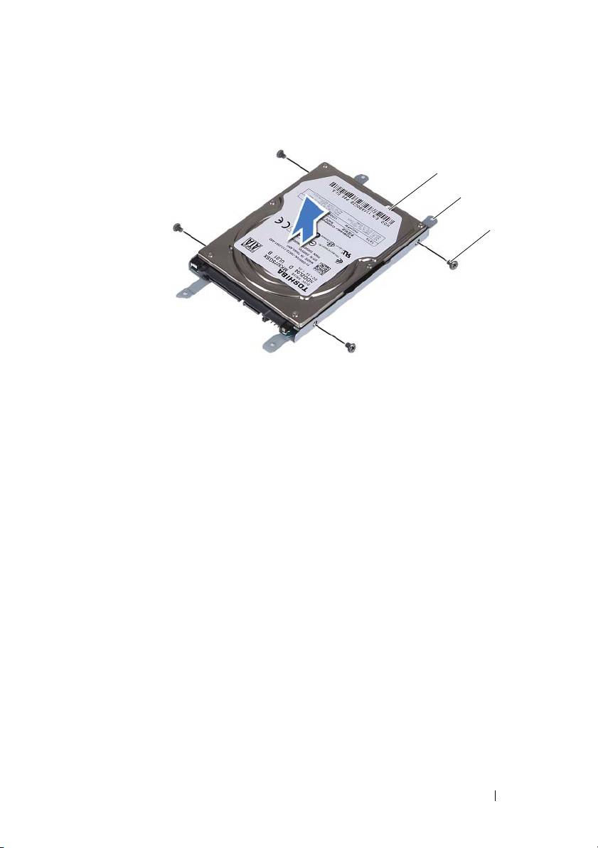
1 hard drive 2 hard-drive bracket
3 screws (4)
Replacing the Hard-Drive Assembly
1
Follow the instructions in "Before You Begin" on page 9.
2
Remove the replacement hard drive from its packaging. Save the packaging
for storing or shipping the old hard drive.
3
Align the screw holes on the hard-drive bracket with the screw holes on the
hard drive.
4
Replace the four screws that secure the hard-drive bracket to the hard
drive.
5
Place the hard-drive assembly in the computer base.
6
Using the pull-tab, slide the hard-drive assembly into the connector on the
system board.
7
Replace the four screws that secure the hard-drive assembly to the
computer base.
8
Replace the module cover. See "Replacing the Module Cover" on page 16.
Hard-Drive Assembly 21
1
2
3

9
Replace the battery. See "Replacing the Battery" on page 14.
CAUTION: Before turning on the computer, replace all screws and ensure that no
stray screws remain inside the computer. Failure to do so may result in damage to
the computer.
10
Connect your computer and all attached devices to electrical outlets, and
turn them on.
11
Install the operating system for your computer, as needed.
12
Install the drivers and utilities for your computer, as needed.
NOTE: For more information on installing the operating system, drivers, and utilities
for your computer, see Me and My Dell at support.dell.com\manuals.
22 Hard-Drive Assembly

6
Optical Drive
WARNING: Before working inside your computer, read the safety information
that shipped with your computer. For additional safety best practices information,
see the Regulatory Compliance Homepage at dell.com/regulatory_compliance.
CAUTION: Only a certified service technician should perform repairs on your
computer. Damage due to servicing that is not authorized by Dell is not covered by
your warranty.
CAUTION: To avoid electrostatic discharge, ground yourself by using a wrist
grounding strap or by periodically touching an unpainted metal surface (such as a
connector on your computer).
Removing the Optical Drive
1
Follow the instructions in "Before You Begin" on page 9.
2
Remove the battery. See "Removing the Battery" on page 13.
3
Remove the module cover. See "Removing the Module Cover" on page 15.
4
Remove the screw that secures the optical-drive assembly to the computer
base.
5
Slide the optical-drive assembly out of the optical-drive bay.
Optical Drive 23
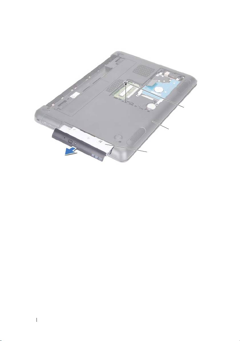
1 optical-drive assembly 2 computer base
3 screw
6
Remove the two screws that secure the optical-drive bracket to the optical
drive.
7
Remove the optical-drive bracket from the optical drive.
8
Gently pry out the tabs on the optical-drive bezel and remove the bezel
from the optical-drive assembly.
24 Optical Drive
3
2
1
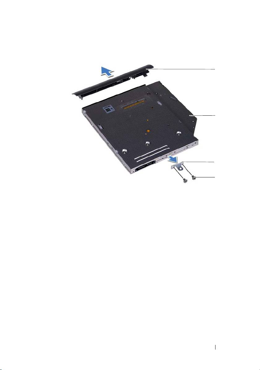
1 optical-drive bezel 2 optical drive
3 optical-drive bracket 4 screws (2)
Replacing the Optical Drive
1
Follow the instructions in "Before You Begin" on page 9.
2
Align the tabs on the optical-drive bezel with the slots on the optical drive
and snap the optical-drive bezel into place.
3
Align the screw holes on the optical-drive bracket with the screw holes on
the optical drive.
4
Replace the two screws that secure the optical-drive bracket to the optical
drive.
5
Slide the optical-drive assembly into the optical-drive bay.
6
Replace the screw that secures the optical-drive assembly to the computer
base.
7
Replace the module cover. See "Replacing the Module Cover" on page 16.
Optical Drive 25
1
2
3
4

8
Replace the battery. See "Replacing the Battery" on page 14.
CAUTION: Before turning on the computer, replace all screws and ensure that no
stray screws remain inside the computer. Failure to do so may result in damage to
the computer.
26 Optical Drive
7
Memory Module(s)
WARNING: Before working inside your computer, read the safety information
that shipped with your computer. For additional safety best practices information,
see the Regulatory Compliance Homepage at dell.com/regulatory_compliance.
CAUTION: Only a certified service technician should perform repairs on your
computer. Damage due to servicing that is not authorized by Dell is not covered by
your warranty.
CAUTION: To avoid electrostatic discharge, ground yourself by using a wrist
grounding strap or by periodically touching an unpainted metal surface (such as a
connector on your computer).
CAUTION: To help prevent damage to the system board, remove the main battery
(see "Removing the Battery" on page 13) before working inside the computer.
Upgrading System Memory
Your computer supports up to two memory-module connectors. You can
access DIMM B connector by removing the module cover at the bottom of
your computer. You can access DIMM A connector by removing the palm-rest
assembly.
You can increase your computer memory by installing memory modules on
the system board. For information on the memory supported by your
computer, see the Comprehensive Specifications for your computer model at
support.dell.com/manuals.
NOTE: Memory modules purchased from Dell are covered under your
computer warranty.
NOTE: If you ordered one memory module with your system, it is installed in the
DIMM A connector.
Removing the Memory Module(s)
1
Follow the instructions in "Before You Begin" on page 9.
2
Remove the battery. See "Removing the Battery" on page 13.
3
Remove the module cover. See "Removing the Module Cover" on page 15.
Memory 27
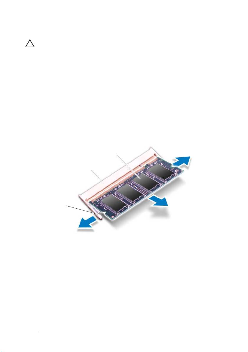
CAUTION: To prevent damage to the memory-module connector, do not use tools
to spread the memory module securing clips.
4
To remove the memory module from the DIMM B connector, go to step 5.
To remove the memory module from the DIMM A connector:
a
Turn the computer over.
b
Remove the keyboard. See "Removing the Keyboard" on page 31.
5
Use your fingertips to carefully spread apart the securing clips on each end
of the memory-module connector until the memory module pops up.
1 securing clips (2) 2 memory-module connector
3 memory module
6
Remove the memory module from the memory-module connector.
Replacing the Memory Module(s)
1
Follow the instructions in "Before You Begin" on page 9.
28 Memory
3
2
1
2
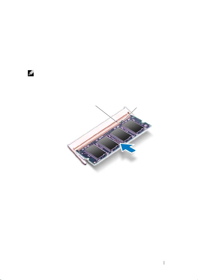
Align the notch on the memory module with the tab in the
memory-module connector.
3
Slide the memory module firmly into the memory-module connector at a
45-degree angle, and then press down the memory module on both sides
until it clicks into place. If you do not hear the click, remove the memory
module and reinstall it.
NOTE: If the memory module is not installed properly, the computer may not boot.
1 tab 2 notch
4
If you replaced the memory module in the DIMM B connector, go to
step 6.
5
If you replaced the memory module in the DIMM A connector:
a
Replace the keyboard. See "Replacing the Keyboard" on page 33.
b
Turn the computer over.
6
Replace the module cover. See "Replacing the Module Cover" on page 16.
7
Replace the battery. See "Replacing the Battery" on page 14.
Memory 29
1
2

Connect your computer and all attached devices to electrical outlets, and turn
them on.
As the computer boots, it detects the memory module(s) and
automatically updates the system configuration information.
To confirm the amount of memory installed in the computer:
Click Start → Control Panel→ System and Security→ System.
30 Memory
8
Keyboard
WARNING: Before working inside your computer, read the safety information
that shipped with your computer. For additional safety best practices information,
see the Regulatory Compliance Homepage at dell.com/regulatory_compliance.
CAUTION: Only a certified service technician should perform repairs on your
computer. Damage due to servicing that is not authorized by Dell is not covered by
your warranty.
CAUTION: To avoid electrostatic discharge, ground yourself by using a wrist
grounding strap or by periodically touching an unpainted metal surface (such as a
connector on your computer).
CAUTION: To help prevent damage to the system board, remove the main battery
(see "Removing the Battery" on page 13) before working inside the computer.
CAUTION: The keycaps on the keyboard are fragile, easily dislodged, and time-
consuming to replace. Be careful when removing and handling the keyboard.
CAUTION: Be extremely careful when removing and handling the keyboard.
Failure to do so could result in scratching the display panel.
Removing the Keyboard
1
Follow the instructions in "Before You Begin" on page 9.
2
Remove the battery. See "Removing the Battery" on page 13.
3
Turn the computer over and open the display as far as possible.
4
Gently slide a plastic scribe between the keyboard and palm-rest assembly.
5
Press the four tabs on the palm-rest assembly and disengage the keyboard.
Keyboard 31
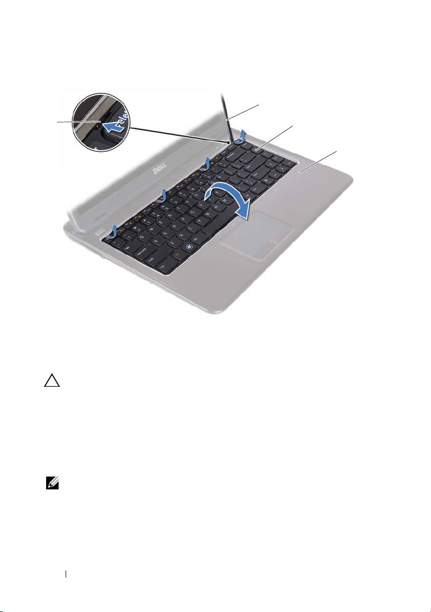
1 tabs (4) 2 plastic scribe
3 keyboard 4 palm-rest assembly
CAUTION: Exercise caution while lifting up the keyboard to avoid pulling the
keyboard connector from the system board forcefully.
6
Carefully lift the keyboard and slide the keyboard tabs out of the slots on
the palm-rest assembly.
7
Turn the keyboard over and place the keyboard on the palm-rest assembly.
8
Lift the connector latches and disconnect the keyboard cable and the
keyboard-backlight cable from the connectors on the system board.
NOTE: The keyboard-backlight cable is available only if you purchased a back-lit
keyboard.
32 Keyboard
2
1
3
4
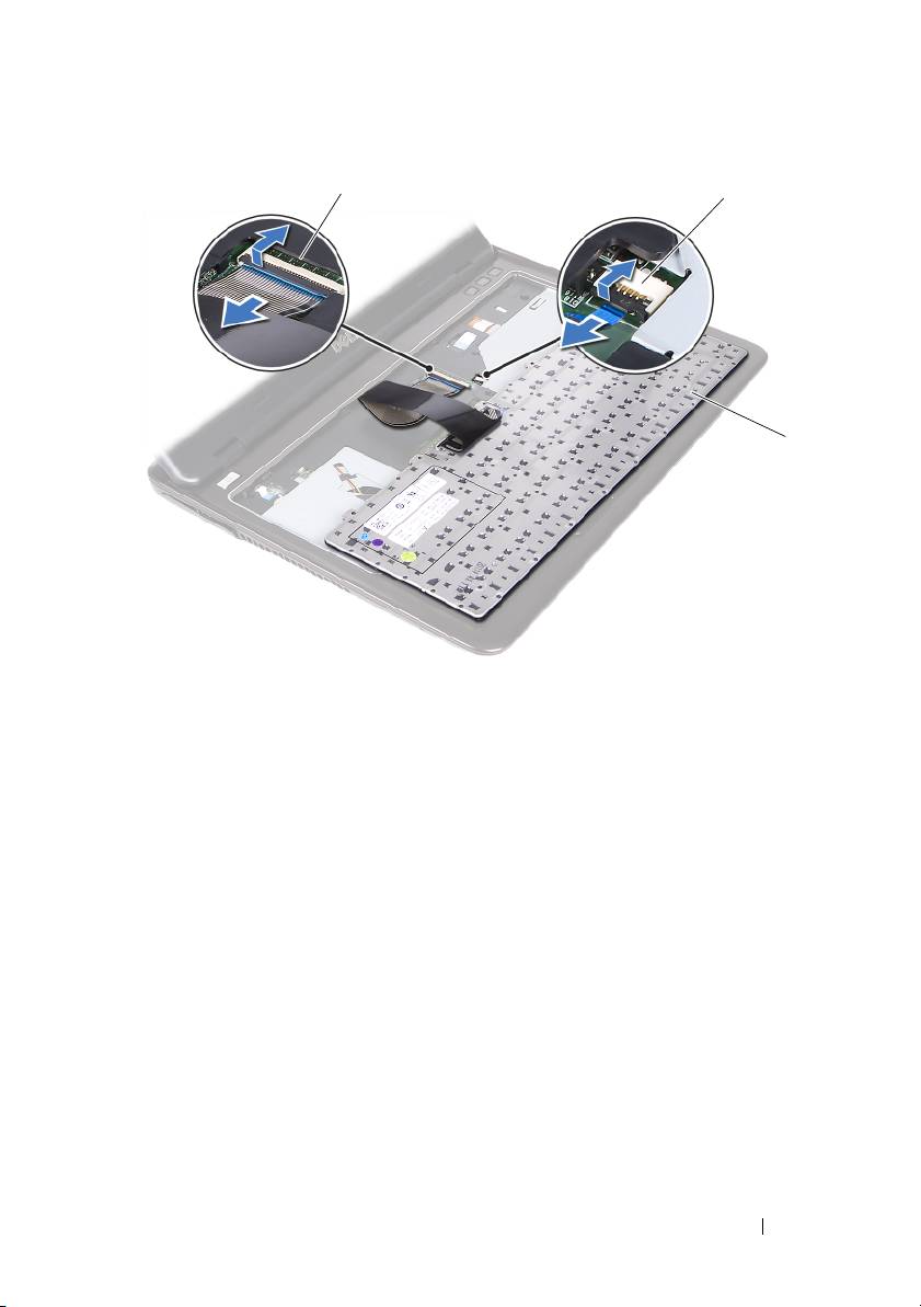
1 keyboard-cable connector 2 keyboard-backlight cable connector
3 keyboard
9
Lift the keyboard off the palm-rest assembly.
Replacing the Keyboard
1
Follow the instructions in "Before You Begin" on page 9.
2
Slide the keyboard cable into the connector on the system board and press
down on the connector latch to secure the keyboard cable.
3
Align the tabs on the keyboard with the slots on the palm-rest assembly
and lower the keyboard into place.
4
Gently press around the edges of the keyboard to secure the keyboard in
place.
5
Replace the battery. See "Replacing the Battery" on page 14.
Keyboard 33
1
2
3

34 Keyboard

9
Palm-Rest Assembly
WARNING: Before working inside your computer, read the safety information
that shipped with your computer. For additional safety best practices information,
see the Regulatory Compliance Homepage at dell.com/regulatory_compliance.
CAUTION: To avoid electrostatic discharge, ground yourself by using a wrist
grounding strap or by periodically touching an unpainted metal surface (such as a
connector on your computer).
CAUTION: Only a certified service technician should perform repairs on your
computer. Damage due to servicing that is not authorized by Dell is not covered by
your warranty.
CAUTION: To help prevent damage to the system board, remove the main battery
(see "Removing the Battery" on page 13) before working inside the computer.
Removing the Palm-Rest Assembly
1
Follow the instructions in "Before You Begin" on page 9.
2
Remove the battery. See "Removing the Battery" on page 13.
3
Remove the module cover. See "Removing the Module Cover" on page 15.
4
Follow the instructions from step 4 to step 5 in "Removing the Optical
Drive" on page 23.
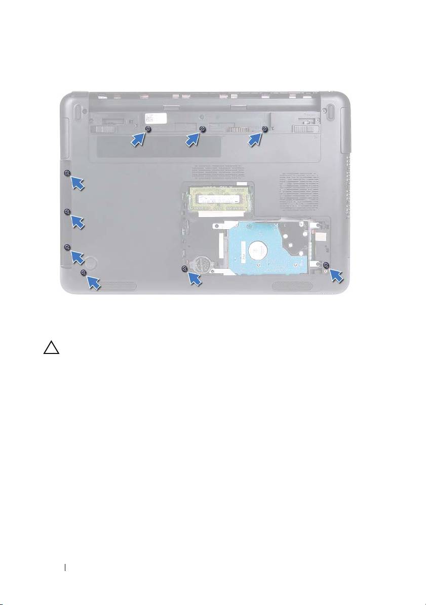
5
Remove the nine screws that secure the palm-rest assembly to the
computer base.
Palm-Rest Assembly 35
6
Turn the computer over.
7
Remove the keyboard. See "Removing the Keyboard" on page 31.
CAUTION: Pull on the plastic tab on top of the connectors to avoid damaging the
connectors.
8
Lift the securing latches and disconnect the power button, touchpad, and
hot-key board cables from their connectors on the system board.
9
Remove the seven screws that secure the palm-rest assembly to the
computer base.
36 Palm-Rest Assembly
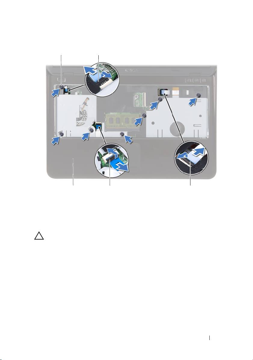
1 screws (7) 2 power-button cable connector
3 hot-key board cable connector 4 touchpad-cable connector
5 palm-rest assembly
CAUTION: Separate the palm-rest assembly from the computer base carefully to
avoid damage to the palm-rest assembly and the display.
10
Lift the palm-rest assembly off the computer base.
Palm-Rest Assembly 37
1
2
5
4
3
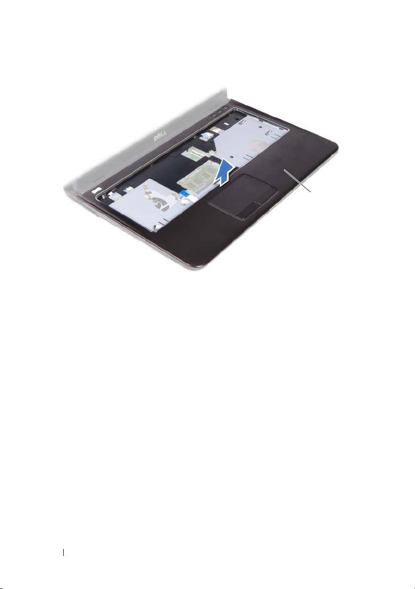
1 palm-rest assembly
Replacing the Palm-Rest Assembly
1
Follow the instructions in "Before You Begin" on page 9.
2
Align the tabs on the palm-rest assembly with the slots on the computer
base and gently snap the palm-rest assembly in place.
3
Slide the power button, touchpad, and hot-key board cables into the
respective connectors on the system board and press down the connector
latches to secure the cables.
4
Replace the seven screws that secure the palm-rest assembly to the
computer base.
5
Replace the keyboard. See "Replacing the Keyboard" on page 33.
6
Turn the computer over and replace the nine screws that secure the
palm-rest assembly to the computer base.
7
Follow the instructions from step 5 to step 6 in "Replacing the Optical
Drive" on page 25.
8
Replace the module cover. See "Replacing the Module Cover" on page 16.
38 Palm-Rest Assembly
1

9
Replace the battery. See "Replacing the Battery" on page 14.
CAUTION: Before turning on the computer, replace all screws and ensure that no
stray screws remain inside the computer. Failure to do so may result in damage to
the computer.
Palm-Rest Assembly 39

40 Palm-Rest Assembly
