Dell Inspiron 14z N411z – страница 4
Инструкция к Ноутбуку Dell Inspiron 14z N411z
13
USB Board
WARNING: Before working inside your computer, read the safety information
that shipped with your computer. For additional safety best practices information,
see the Regulatory Compliance Homepage at dell.com/regulatory_compliance.
CAUTION: Only a certified service technician should perform repairs on your
computer. Damage due to servicing that is not authorized by Dell is not covered by
your warranty.
CAUTION: To avoid electrostatic discharge, ground yourself by using a wrist
grounding strap or by periodically touching an unpainted metal surface (such as a
connector on your computer).
CAUTION: To help prevent damage to the system board, remove the main battery
(see "Removing the Battery" on page 13) before working inside the computer.
Removing the USB Board
1
Follow the instructions in "Before You Begin" on page 9.
2
Remove the battery. See "Removing the Battery" on page 13.
3
Remove the module cover. See "Removing the Module Cover" on page 15.
4
Remove the optical-drive assembly. "Removing the Optical Drive" on
page 23.
5
Remove the keyboard. See "Removing the Keyboard" on page 31.
6
Remove the palm-rest assembly. See "Removing the Palm-Rest Assembly"
on page 35.
7
Remove the display assembly. See "Removing the Display Assembly" on
page 45.
8
Remove the hinge cover. See "Removing the Hinge Cover" on page 48.
9
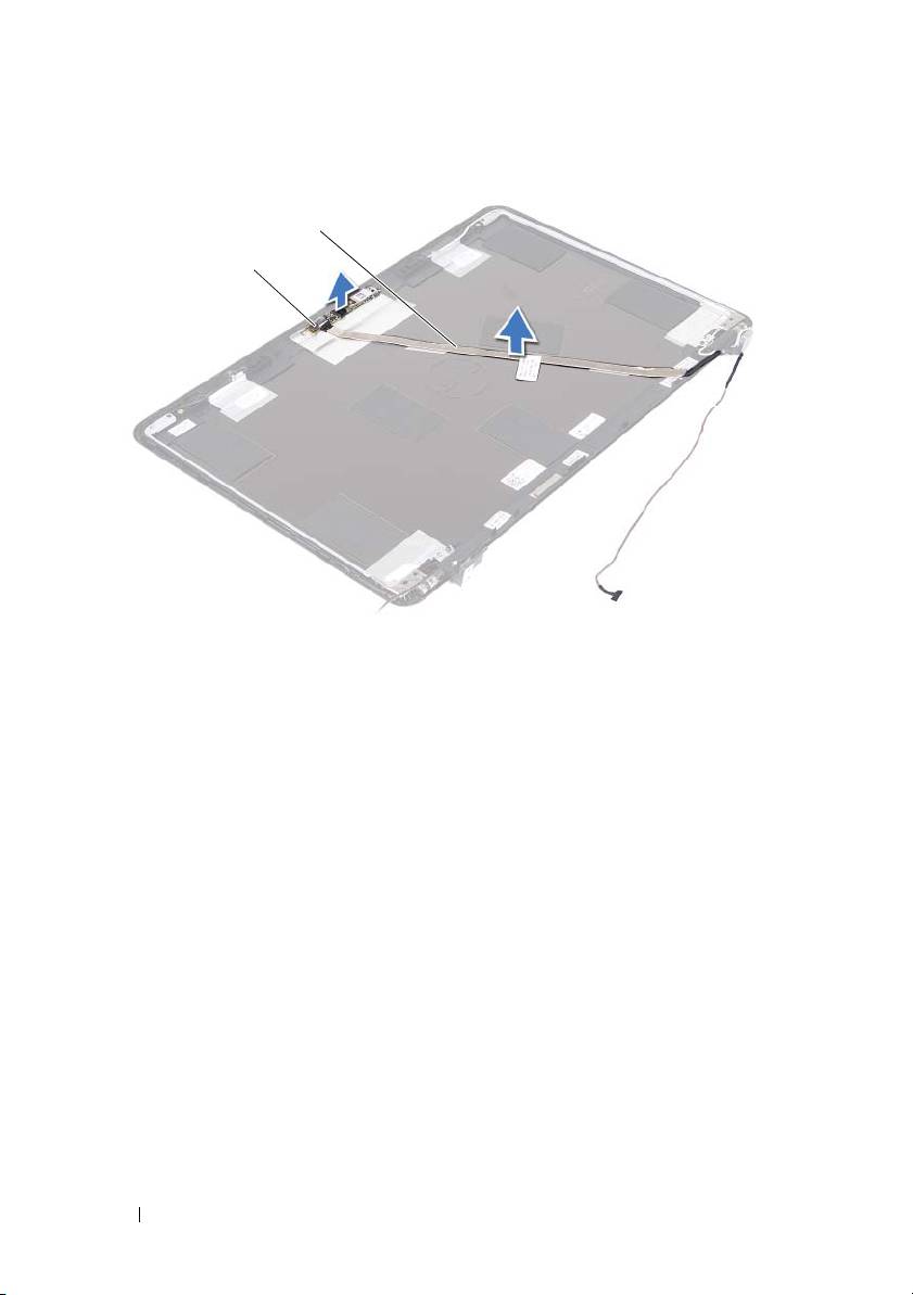
Lift the securing latches and disconnect the USB-board cable from the
connector on the USB board and the system board.
USB Board 61
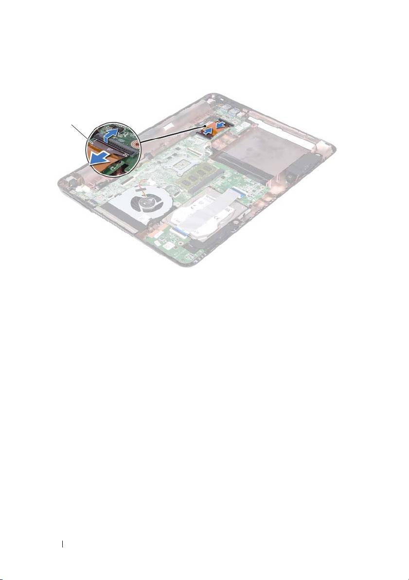
1 USB-board cable
10
Remove the screw that secures the USB board to the computer base.
62 USB Board
1
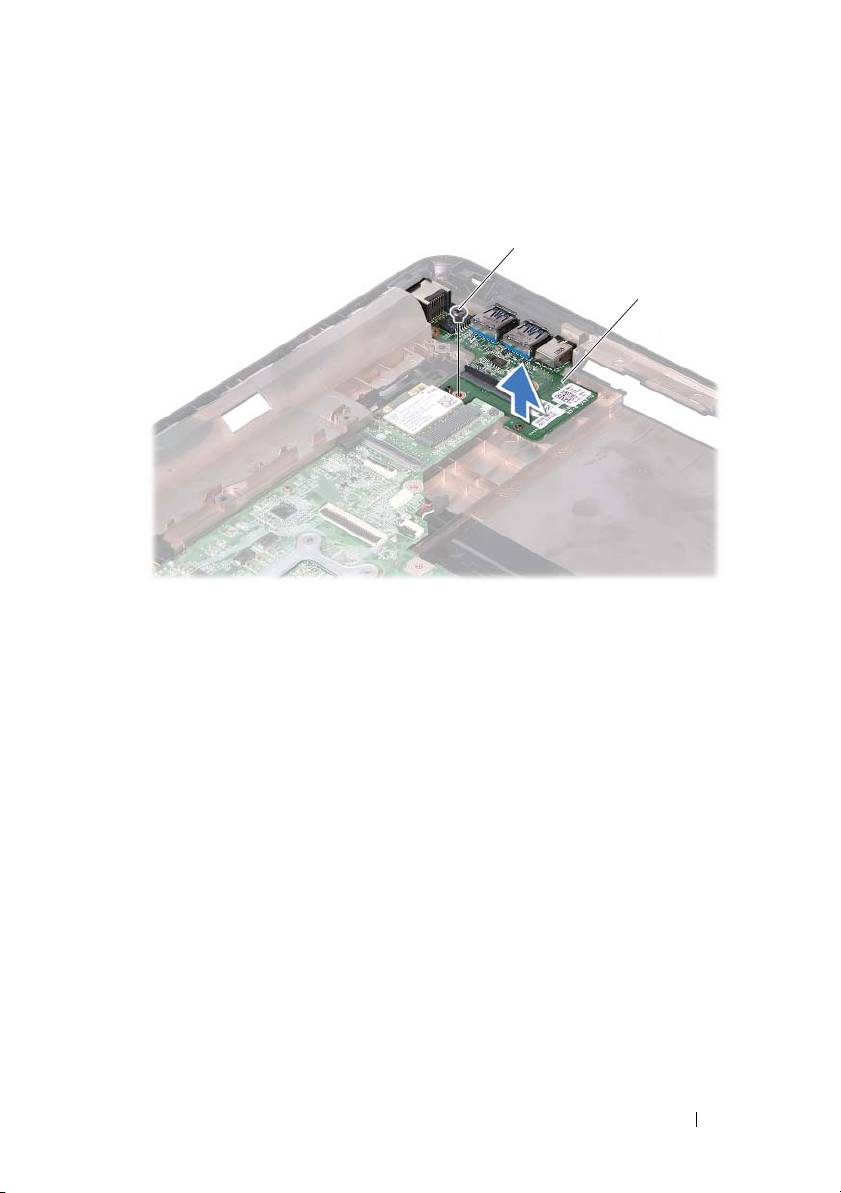
1 screw 2 USB board
11
Lift the USB board off the computer base.
Replacing the USB Board
1
Follow the instructions in "Before You Begin" on page 9.
2
Align the screw hole on the USB board with the screw hole on the system
board.
3
Replace the screw that secures the USB board to the system board.
4
Slide the USB-board cable into the connectors on the USB board and the
system board, and press down the securing latches.
5
Replace the hinge cover. See "Replacing the Hinge Cover" on page 49.
6
Replace the display assembly. See "Replacing the Display Assembly" on
page 47.
USB Board 63
1
2

7
Replace the palm-rest assembly. See "Replacing the Palm-Rest Assembly"
on page 38.
8
Replace the keyboard. See "Replacing the Keyboard" on page 33.
9
Follow the instructions from step 5 to step 6 in "Replacing the Optical
Drive" on page 25.
10
Replace the module cover. See "Replacing the Module Cover" on page 16.
11
Replace the battery. See "Replacing the Battery" on page 14.
CAUTION: Before turning on the computer, replace all screws and ensure that no
stray screws remain inside the computer. Failure to do so may result in damage to
the computer.
64 USB Board
14
Camera Module
WARNING: Before working inside your computer, read the safety information
that shipped with your computer. For additional safety best practices information,
see the Regulatory Compliance Homepage at dell.com/regulatory_compliance.
CAUTION: Only a certified service technician should perform repairs on your
computer. Damage due to servicing that is not authorized by Dell is not covered by
your warranty.
CAUTION: To avoid electrostatic discharge, ground yourself by using a wrist
grounding strap or by periodically touching an unpainted metal surface (such as a
connector on your computer).
CAUTION: To help prevent damage to the system board, remove the main battery
(see "Removing the Battery" on page 13) before working inside the computer.
Removing the Camera Module
1
Follow the instructions in "Before You Begin" on page 9.
2
Remove the battery. See "Removing the Battery" on page 13.
3
Remove the module cover. See "Removing the Module Cover" on page 15.
4
Follow the instructions in step 4 to step 5 of "Removing the Optical Drive"
on page 23.
5
Remove the keyboard. See "Removing the Keyboard" on page 31.
6
Remove the palm-rest assembly. See "Removing the Palm-Rest Assembly"
on page 35.
7
Remove the display assembly. See "Removing the Display Assembly" on
page 45.
8
Remove the display bezel. See "Removing the Display Bezel" on page 50.
9
Remove the display panel. See "Removing the Display Panel" on page 51.
10
Lift the camera cable off the adhesive tapes on the display cover.
Camera Module 65
1 camera module 2 camera cable
11
Lift the camera module from the alignment posts and remove the camera
module from the display cover.
12
Remove the tape that secures the camera cable to the camera module.
66 Camera Module
2
1
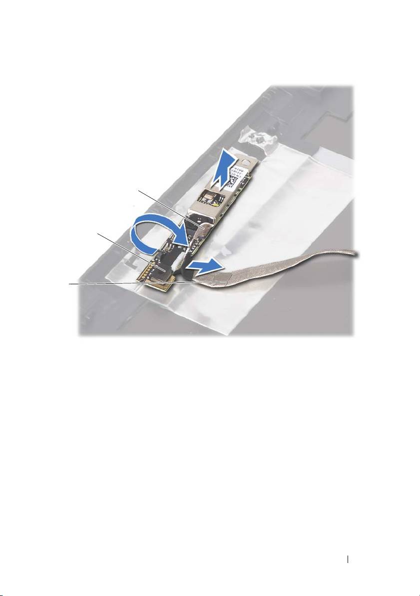
1 camera cable 2 camera module
3 adhesive tape
13
Disconnect the camera cable from the connector on the camera module.
Replacing the Camera Module
1
Follow the instructions in "Before You Begin" on page 9.
2
Connect the camera cable to the camera module, and adhere the tape that
secures the cable to the camera module.
3
Align the camera module to the alignment posts in the display cover and
place the camera module in the display cover.
4
Adhere the camera cable to the tapes on the display cover.
5
Replace the display panel. See "Replacing the Display Panel" on page 53.
Camera Module 67
3
2
1

6
Replace the display bezel. See "Replacing the Display Bezel" on page 51.
7
Replace the display assembly. See "Replacing the Display Assembly" on
page 47.
8
Replace the palm-rest assembly. See "Replacing the Palm-Rest Assembly"
on page 38.
9
Replace the keyboard. See "Replacing the Keyboard" on page 33.
10
Follow the instructions from step 5 to step 6 in "Replacing the Optical
Drive" on page 25.
11
Replace the module cover. See "Replacing the Module Cover" on page 16.
12
Replace the battery. See "Replacing the Battery" on page 14.
CAUTION: Before turning on the computer, replace all screws and ensure that no
stray screws remain inside the computer. Failure to do so may result in damage to
the computer.
68 Camera Module

15
Thermal Fan
WARNING: Before working inside your computer, read the safety information
that shipped with your computer. For additional safety best practices information,
see the Regulatory Compliance Homepage at dell.com/regulatory_compliance.
CAUTION: Only a certified service technician should perform repairs on your
computer. Damage due to servicing that is not authorized by Dell is not covered by
your warranty.
CAUTION: To avoid electrostatic discharge, ground yourself by using a wrist
grounding strap or by periodically touching an unpainted metal surface (such as a
connector on your computer).
CAUTION: To help prevent damage to the system board, remove the main battery
(see "Removing the Battery" on page 13) before working inside the computer.
Removing the Thermal Fan
1
Follow the instructions in "Before You Begin" on page 9.
2
Remove the battery. See "Removing the Battery" on page 13.
3
Remove the module cover. See "Removing the Module Cover" on page 15.
4
Remove the optical-drive assembly. "Removing the Optical Drive" on
page 23.
5
Remove the keyboard. See "Removing the Keyboard" on page 31.
6
Remove the palm-rest assembly. See "Removing the Palm-Rest Assembly"
on page 35.
7
Remove the screw that secures the thermal fan to the computer base.
8
Disconnect the thermal-fan cable from the connector on the system board.
9
Lift the thermal fan off the computer base.
Thermal Fan 69
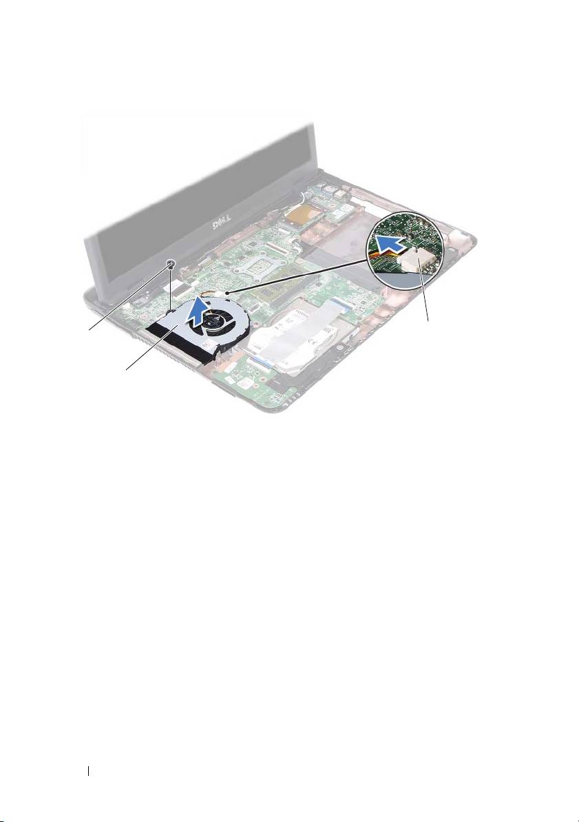
1 screw 2 thermal fan
3 system-board connector
Replacing the Thermal Fan
1
Follow the instructions in "Before You Begin" on page 9.
2
Align the thermal fan to the alignment posts in the computer base and
place the thermal fan in the computer base.
3
Replace the screw that secures the thermal fan to the computer base.
4
Connect the thermal-fan cable to the connector on the system board.
5
Replace the palm-rest assembly. See "Replacing the Palm-Rest Assembly"
on page 38.
6
Replace the keyboard. See "Replacing the Keyboard" on page 33.
7
Follow the instructions from step 5 to step 6 in "Replacing the Optical
Drive" on page 25.
8
Replace the module cover. See "Replacing the Module Cover" on page 16.
70 Thermal Fan
1
3
2

9
Replace the battery. See "Replacing the Battery" on page 14.
CAUTION: Before turning on the computer, replace all screws and ensure that no
stray screws remain inside the computer. Failure to do so may result in damage to
the computer.
Thermal Fan 71

72 Thermal Fan

16
System Board
WARNING: Before working inside your computer, read the safety information
that shipped with your computer. For additional safety best practices information,
see the Regulatory Compliance Homepage at dell.com/regulatory_compliance.
CAUTION: Only a certified service technician should perform repairs on your
computer. Damage due to servicing that is not authorized by Dell is not covered by
your warranty.
CAUTION: To avoid electrostatic discharge, ground yourself by using a wrist
grounding strap or by periodically touching an unpainted metal surface (such as a
connector on your computer).
CAUTION: To help prevent damage to the system board, remove the main battery
(see "Removing the Battery" on page 13) before working inside the computer.
Removing the System Board
1
Follow the instructions in "Before You Begin" on page 9.
2
Remove the battery. See "Removing the Battery" on page 13.
3
Remove the module cover. See "Removing the Module Cover" on page 15.
4
Follow the instructions from step 4 to step 5 in "Removing the Optical
Drive" on page 23.
5
Remove the hard-drive assembly. See "Removing the Hard-Drive
Assembly" on page 19.
6
Remove the keyboard. See "Removing the Keyboard" on page 31.
7
Remove the memory module(s). See "Removing the Memory Module(s)"
on page 27.
8
Remove the palm-rest assembly. See "Removing the Palm-Rest Assembly"
on page 35.
9
Remove the wireless mini-card. See "Removing the Mini-Card" on page 41.
10
Remove the display assembly. See "Removing the Display Assembly" on
page 45.
11
Remove the thermal fan. See "Removing the Thermal Fan" on page 69.
System Board 73
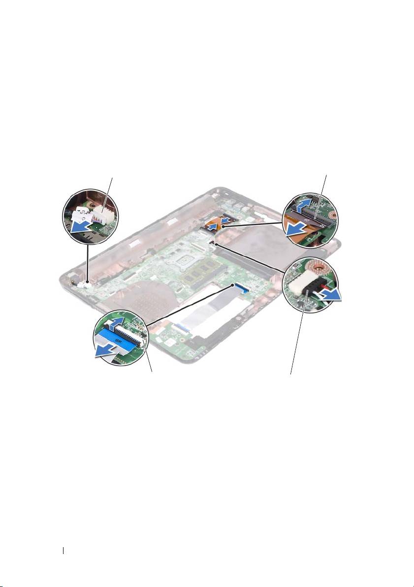
12
Disconnect the DC-in connector cable and the speaker cable from the
connectors on the system board.
13
Lift the securing latches and disconnect the USB-board cable from the
connectors on the system board and the USB board.
14
Lift the securing latch and disconnect the media-card reader board cable
from the connector on the system board.
1 DC-in cable connector 2 USB-board cable connectors (2)
3 speaker-cable connector 4 media-card reader cable connectors
(2)
15
Remove the four screws that secure the system-board assembly to the
computer base.
16
Carefully ease the ports on the system-board assembly out of the slots in
the computer base and lift the system-board assembly out of the computer
base.
74 System Board
2
1
4
3
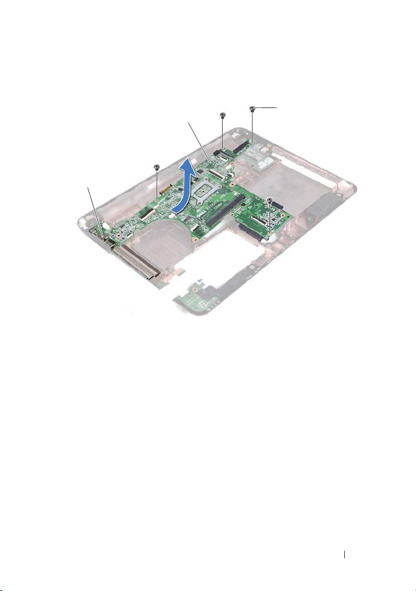
1 ports 2 system board
3 screws (4)
17
Turn the system-board assembly over.
18
Remove the heat-sink assembly. See "Removing the Heat-Sink Assembly"
on page 79.
Replacing the System Board
1
Follow the instructions in "Before You Begin" on page 9.
2
Replace the heat-sink assembly. See "Replacing the Heat-Sink Assembly"
on page 80.
3
Turn the system-board assembly over.
System Board 75
3
2
1

4
Ease the ports on the system-board assembly into the slots on the
computer base.
5
Align the system-board assembly to the alignment posts in the computer
base and place the system board in the computer base.
NOTE: Ensure that the speaker-cable connector is not caught between the
system-board assembly and the computer base.
6
Replace the four screws that secure the system-board assembly to the
computer base.
7
Connect the DC-in connector cable and the speaker cable to the
connectors on the system board.
8
Connect the USB-board cable to the connectors on the system board and
the USB board. Press down the securing latches.
9
Connect the media-card reader board cable to the connector on the system
board. Press down the securing latch.
10
Replace the wireless mini-card. See "Replacing the Mini-Card" on page 42.
11
Replace the thermal fan. See "Replacing the Thermal Fan" on page 70.
12
Replace the display assembly. See "Replacing the Display Assembly" on
page 47.
13
Replace the memory module(s). See "Replacing the Memory Module(s)"
on page 28.
14
Replace the palm-rest assembly. See "Replacing the Palm-Rest Assembly"
on page 38.
15
Replace the keyboard. See "Replacing the Keyboard" on page 33.
16
Replace the hard-drive assembly. See "Replacing the Hard-Drive Assembly"
on page 21.
17
Follow the instructions from step 5 to step 6 in "Replacing the Optical
Drive" on page 25.
18
Replace the module cover. See "Replacing the Module Cover" on page 16.
19
Replace the battery. See "Replacing the Battery" on page 14.
CAUTION: Before turning on the computer, replace all screws and ensure that no
stray screws remain inside the computer. Failure to do so may result in damage to
the computer.
20
Turn on the computer.
76 System Board

NOTE: After you have replaced the system board, type the computer’s Service Tag
into the BIOS of the replacement system board.
21
Enter the service tag. See "Entering the Service Tag in the BIOS" on
page 77.
Entering the Service Tag in the BIOS
1
Ensure that the AC adapter is plugged in and that the main battery is
installed properly.
2
Turn on the computer.
3
Press <F2> during POST to enter the system setup program.
4
Navigate to the
Security
tab and type the service tag in the
Set Service Tag
field.
System Board 77

78 System Board
17
Heat-Sink Assembly
WARNING: Before working inside your computer, read the safety information
that shipped with your computer. For additional safety best practices information,
see the Regulatory Compliance Homepage at dell.com/regulatory_compliance.
WARNING: If you remove the heat-sink assembly from the computer when the
heat sink is hot,
do not touch
the metal housing of the heat-sink assembly.
CAUTION: Only a certified service technician should perform repairs on your
computer. Damage due to servicing that is not authorized by Dell is not covered by
your warranty.
CAUTION: To avoid electrostatic discharge, ground yourself by using a wrist
grounding strap or by periodically touching an unpainted metal surface (such as a
connector on your computer).
CAUTION: To help prevent damage to the system board, remove the main battery
(see "Removing the Battery" on page 13) before working inside the computer.
Removing the Heat-Sink Assembly
1
Follow the instructions in "Before You Begin" on page 9.
2
Remove the battery. See "Removing the Battery" on page 13.
3
Remove the module cover. See "Removing the Module Cover" on page 15.
4
Follow the instructions from step 4 to step 5 in "Removing the Optical
Drive" on page 23.
5
Remove the hard-drive assembly. See "Removing the Hard-Drive
Assembly" on page 19.
6
Remove the keyboard. See "Removing the Keyboard" on page 31.
7
Remove the memory module(s). See "Removing the Memory Module(s)"
on page 27.
8
Remove the palm-rest assembly. See "Removing the Palm-Rest Assembly"
on page 35.
9
Remove the wireless mini-card. See "Removing the Mini-Card" on page 41.
Heat-Sink Assembly 79
10
Remove the display assembly. See "Removing the Display Assembly" on
page 45.
11
Remove the thermal fan. See "Removing the Thermal Fan" on page 69.
12
Follow the instructions from step 12 to step 17 in "Removing the System
Board" on page 73.
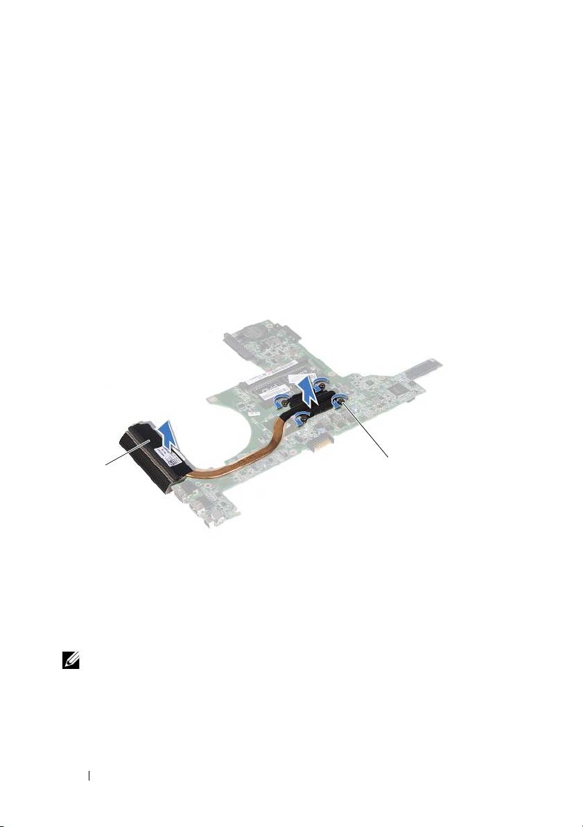
13
In the sequential order, as indicated on the heat sink, loosen the four
captive screws that secure the heat sink-assembly to the system board.
14
Lift the heat-sink assembly away from the system board.
1 heat-sink assembly 2 captive screws (4)
Replacing the Heat-Sink Assembly
NOTE: The original thermal pad can be reused if the original processor and heat
sink are reinstalled together. If either the processor or heat sink is replaced, use the
thermal pad provided in the kit to ensure that thermal conductivity is achieved.
1
Follow the instructions in "Before You Begin" on page 9.
2
Clean the thermal grease from the bottom of the heat sink and reapply it.
80 Heat-Sink Assembly
2
1
