Asus P5E3 Premium WiFi-AP@n: Hardware
Hardware: Asus P5E3 Premium WiFi-AP@n

This chapter lists the hardware setup
procedures that you have to perform
when installing system components. It
includes description of the jumpers and
connectors on the motherboard.
Hardware
2
information

Chapter summary
2
2.1 Before you proceed ..................................................................... 2-1
2.2 Motherboard overview .................................................................
2-2
2.3 Central Processing Unit (CPU) ...................................................
2-6
2.4 System memory .........................................................................
2-13
2.5 Expansion slots ..........................................................................
2-18
2.6 Jumper ........................................................................................
2-22
2.7 Connectors .................................................................................
2-24
ASUS P5E3 Premium/WiFi-AP @n
2.1 Before you proceed
Take note of the following precautions before you install motherboard components
or change any motherboard settings.
• Unplug the power cord from the wall socket before touching any
component.
• Use a grounded wrist strap or touch a safely grounded object or
a metal object, such as the power supply case, before handling
components to avoid damaging them due to static electricity.
• Hold components by the edges to avoid touching the ICs on them.
• Whenever you uninstall any component, place it on a grounded
antistatic pad or in the bag that came with the component.
• Before you install or remove any component, ensure
that the ATX power supply is switched off or the power cord is detached
from the power supply. Failure to do so may cause severe damage to the
motherboard, peripherals, and/or components.
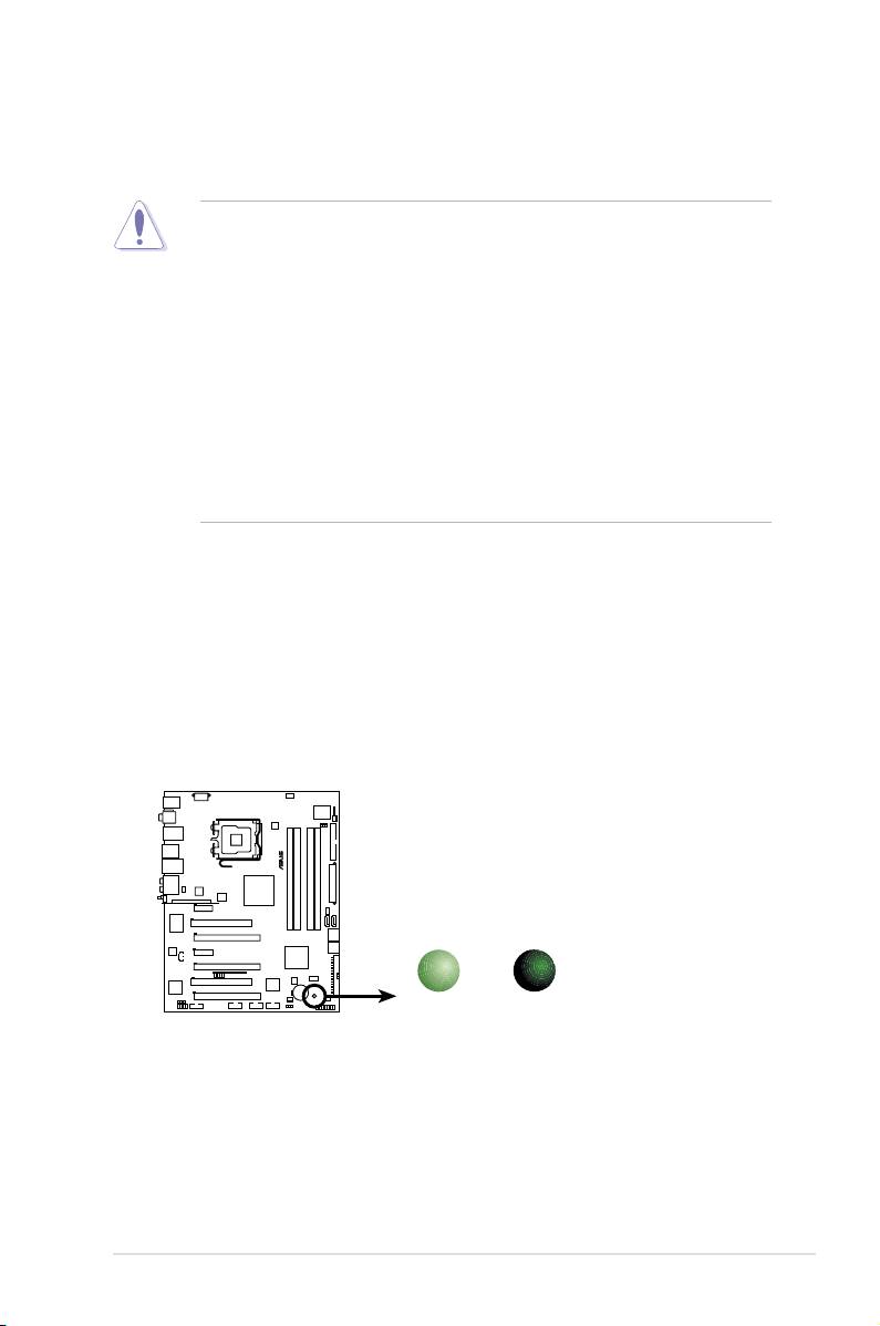
Onboard LED
The motherboard comes with a standby power LED. The green LED lights up
to indicate that the system is ON, in sleep mode, or in soft-off mode. This is a
reminder that you should shut down the system and unplug the power cable before
removing or plugging in any motherboard component. The illustration below shows
the location of the onboard LED.
ASUS P5E3 Premium/WiFi-AP @n 2-1
®
P5E3 PREMIUM
SB_PWR
ON
OFF
Standby
Powered
P5E3 Premium/WiFi-AP @n
Power
Off
Onboard LED
2.2 Motherboard overview
Before you install the motherboard, study the conguration of your chassis to
ensure that the motherboard ts into it.
Make sure to unplug the power cord before installing or removing the
motherboard. Failure to do so can cause you physical injury and damage
motherboard components.
2.2.1 Placement direction
When installing the motherboard, make sure that you place it into the chassis in the
correct orientation. The edge with external ports goes to the rear part of the chassis
as indicated in the image below.
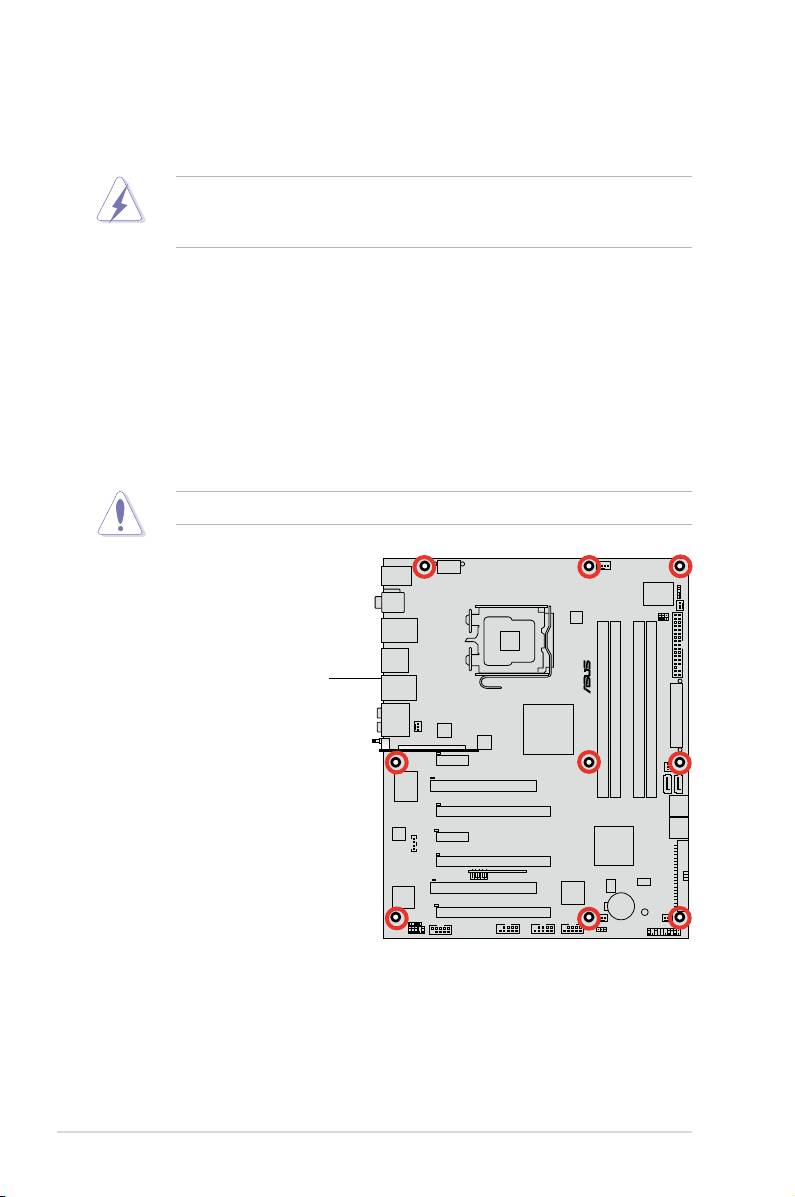
2.2.2 Screw holes
Place nine (9) screws into the holes indicated by circles to secure the motherboard
to the chassis.
DO NOT overtighten the screws! Doing so can damage the motherboard.
Place this side towards
the rear of the chassis
2-2 Chapter 2: Hardware information
®
P5E3 PREMIUM
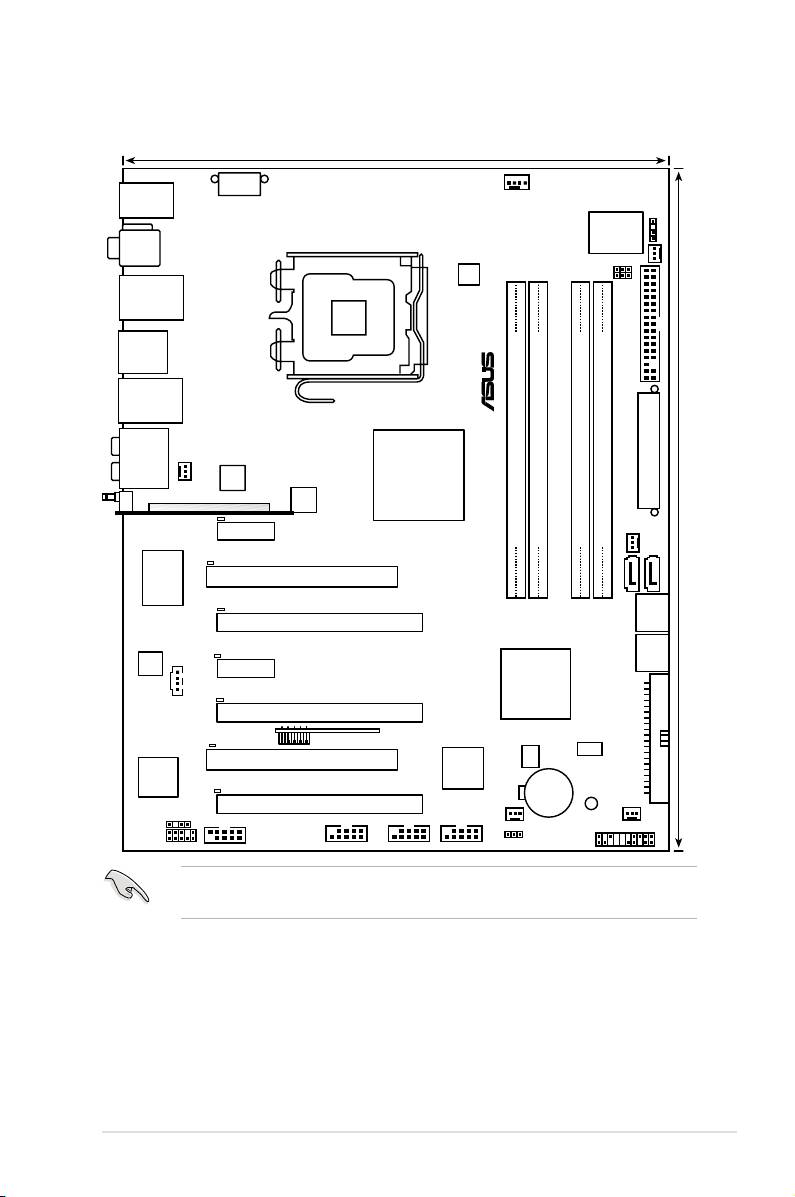
2.2.3 Motherboard layout
Refer to 2.7 Connectors for more information about rear panel connectors and
internal connectors.
ASUS P5E3 Premium/WiFi-AP @n 2-3
24.5cm (9.6in)
CPU_FAN
KB_USB56
EATX12V
CHASSIS
Super
I/O
SPDIF_O12
PWR_FAN
OV_CPU
EPU
OV_NB
LGA775
LAN2_USB34
F_ESATA12
®
FLOPPY
LAN1_USB12
AUDIO
®
Intel
CHA_FAN1
88E8056
EATXPWR
X48
WFG
ICS
DET_X1_1
PCIEX1_1
CHA_FAN2
DDR3 DIMM_A1 (64 bit,240-pin module)
DDR3 DIMM_A2 (64 bit,240-pin module)
DDR3 DIMM_B1 (64 bit,240-pin module)
DDR3 DIMM_B2 (64 bit,240-pin module)
SATA2
DET_PCI1
30.5cm (12.0in)
PCI1
SATA1
RTL8110SC
P5E3 PREMIUM
DET_X16_1
PCIEX16_1
SATA34
DET_X1_2
AD1988B
SATA56
PCIEX1_2
®
Intel
CD
ICH9R
DET_X16_2
PRI_EIDE
PCIEX16_2
DET_PCI2
USB910_EXPRESS_GATE
BIOS
ASM
8283
PCI2
agere
L-FW3227-100
JMB363
CR2032 3V
DET_X16_3
Lithium Cell
CMOS Power
CHA_FAN4
PCIEX16_3
SPDIF_OUT
COM1
IE1394_2 USB78
USB1112
SB_PWR
CHA_FAN3
PANEL
AAFP
CLRTC
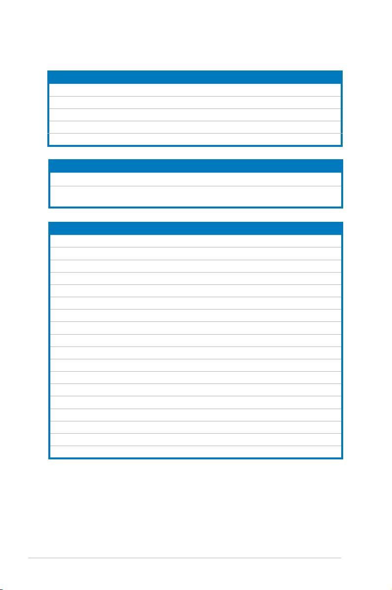
2.2.4 Layout contents
Slots Page
1. DDR3 DIMM slots 2-13
2. PCI slots
2-20
3. PCI Express x 1 slots
2-20
4.
PCI Express 2.0 x16 slots
2-20
5. Universal PCI Express x16 slot
2-20
Jumpers Page
1. Clear RTC RAM (3-pin CLRTC) 2-22
2. CPU / Northbridge overvoltage setting
2-23
(3-pin OV_CPU, 3-pin OV_NB)
Rear panel connectors Page
1. PS/2 keyboard port (purple)
2-24
2. Coaxial S/PDIF Out port
2-24
3. LAN 1 (RJ-45) port
2-24
4. IEEE 1394a port
2-24
5. LAN 2 (RJ-45) port
2-24
6. Center/Subwoofer port (orange)
2-24
7. Rear Speaker Out port (black)
2-24
8. Line In port (light blue)
2-24
9. Line Out port (lime)
2-24
10. Wireless LAN ports
2-25
11. Wireless LAN Activity LED
2-25
12. Microphone port (pink)
2-25
13. Side Speaker Out port (gray)
2-25
14. USB 2.0 ports 1 and 2
2-25
15. External SATA port 1/2
2-25
16. USB 2.0 ports 3 and 4
2-26
17. Optical S/PDIF Out port
2-26
18. USB 2.0 ports 5 and 6
2-26
2-4 Chapter 2: Hardware information

Internal connectors Page
1. Floppy disk drive connector (34-1 pin FLOPPY)
2-27
2. IDE connector (40-1 pin PRI_EIDE))
2-28
3. ICH9R Serial ATA connectors (7-pin SATA1-6[red])
2-29
4. USB connectors (10-1 pin USB78, USB910, USB1112)
2-30
5. IEEE 1394a port connector (10-1 pin IE1394_2)
2-31
6. CPU, chassis and power fan connectors
2-32
(4-pin CPU_FAN, 3-pin CHA_FAN1-4, 3-pin PWR_FAN)
7. Chassis intrusion connector (4-1 pin CHASSIS)
2-33
8. ATX power connectors (24-pin EATXPWR, 2x4-pin EATX12V)
2-34
9. Front panel audio connector (10-1 pin AAFP)
2-35
10. Optical drive audio connector (4-pin CD)
2-36
11. Digital audio connector (4-1 pin SPDIF, for ASUS HDMI card)
2-36
12. System panel connector (20-8 pin PANEL)
2-37
13. ASUS Q-Connector (system panel)
2-38
ASUS P5E3 Premium/WiFi-AP @n 2-5
2.3 Central Processing Unit (CPU)
®
The motherboard comes with a surface mount LGA775 socket designed for the Intel
®
®
Core™2 Extreme / Core™2 Quad / Core™2 Duo / Pentium
Extreme / Pentium
D /
®
Pentium
4 Processors.
• Make sure that all power cables are unplugged before installing the CPU.
• If installing a dual-core CPU, connect the chassis fan cable to the
CHA_FAN1 connector to ensure system stability.
• Due to the chipset limitation, we recommend you use FSB 800MHz CPU or
above.
•
Upon purchase of the motherboard, make sure that the PnP cap is on
the socket and the socket contacts are not bent. Contact your retailer
immediately if the PnP cap is missing, or if you see any damage to the PnP
cap/socket contacts/motherboard components. ASUS will shoulder the cost
of repair only if the damage is shipment/transit-related.
•
Keep the cap after installing the motherboard. ASUS will process Return
Merchandise Authorization (RMA) requests only if the motherboard comes
with the cap on the LGA775 socket.
• The product warranty does not cover damage to the socket contacts
resulting from incorrect CPU installation/removal, or misplacement/loss/
incorrect removal of the PnP cap.
2-6 Chapter 2: Hardware information
2.3.1 Installing the CPU
To install a CPU:
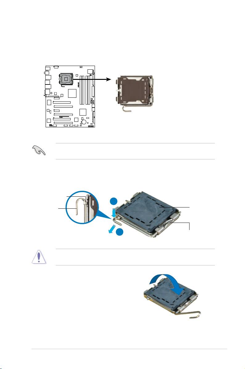
1. Locate the CPU socket on the motherboard.
Before installing the CPU, make sure that the cam box is facing towards you
and the load lever is on your left.
2. Press the load lever with your thumb (A), then move it to the left (B) until it is
released from the retention tab.
Retention tab
A
PnP cap
Load lever
B
This side of the socket box
should face you.
To prevent damage to the socket pins, do not remove the PnP cap unless you
are installing a CPU.
3. Lift the load lever in the direction of
the arrow to a 135º angle.
ASUS P5E3 Premium/WiFi-AP @n 2-7
®
P5E3 PREMIUM
P5E3 Premium/WiFi-AP @n
CPU Socket 775
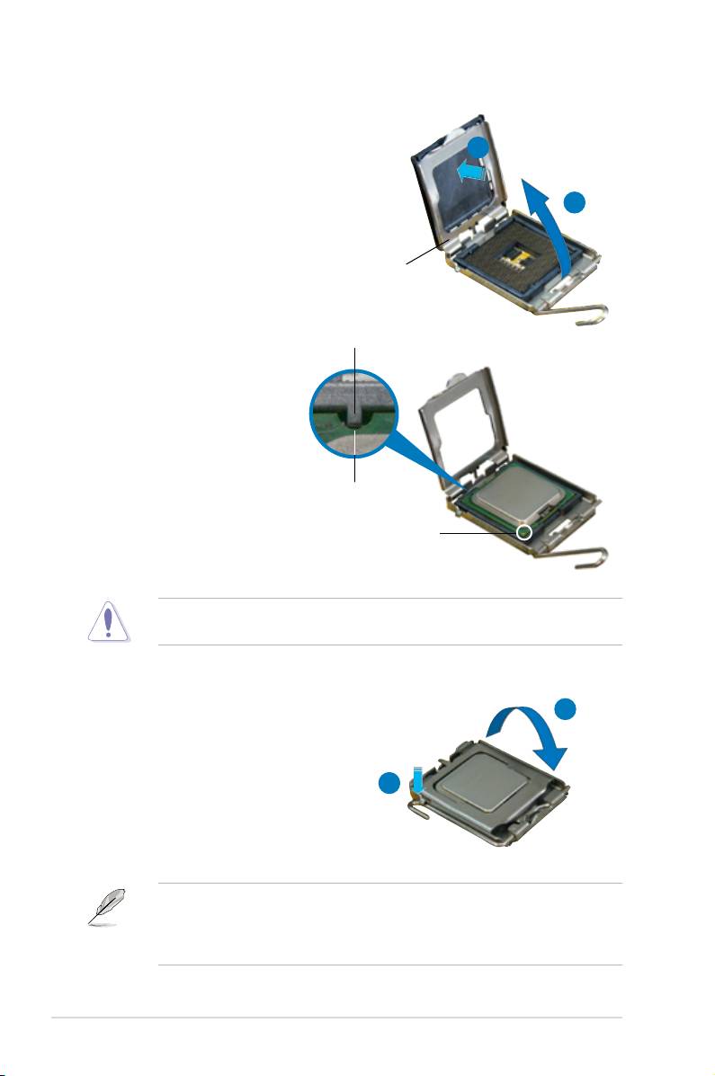
4. Lift the load plate with your thumb
and forenger to a 100º angle (A),
B
then push the PnP cap from the load
plate window to remove (B).
A
Load plate
Alignment key
5. Position the CPU over the
socket, making sure that
the gold triangle is on the
bottom-left corner of the
socket then t the socket
alignment key into the
CPU notch
CPU notch.
Gold triangle mark
The CPU ts in only one correct orientation. DO NOT force the CPU into the
socket to prevent bending the connectors on the socket and damaging the CPU!
A
6. Close the load plate (A), then
push the load lever (B) until it
snaps into the retention tab.
7. If installing a dual-core CPU,
B
connect the chassis fan cable
to the CHA_FAN1 connector to
ensure system stability.
®
®
The motherboard supports Intel
LGA775 processors with the Intel
Enhanced
®
Memory 64 Technology (EM64T), Enhanced Intel SpeedStep
Technology
(EIST), and Hyper-Threading Technology. Refer to the Appendix for more
information on these CPU features.
2-8 Chapter 2: Hardware information
2.3.2 Installing the CPU heatsink and fan
®
The Intel
LGA775 processor requires a specially designed heatsink and fan
assembly to ensure optimum thermal condition and performance.
®
•
When you buy a boxed Intel
processor, the package includes the CPU fan
and heatsink assembly. If you buy a CPU separately, make sure that you
®
use only Intel
-certied multi-directional heatsink and fan.
®
•
Your Intel
LGA775 heatsink and fan assembly comes in a push-pin design
and requires no tool to install.
•
If you purchased a separate CPU heatsink and fan assembly, make sure
that you have properly applied Thermal Interface Material to the CPU
heatsink or CPU before you install the heatsink and fan assembly.
Make sure that you have installed the motherboard to the chassis before you
install the CPU fan and heatsink assembly.
To install the CPU heatsink and fan:
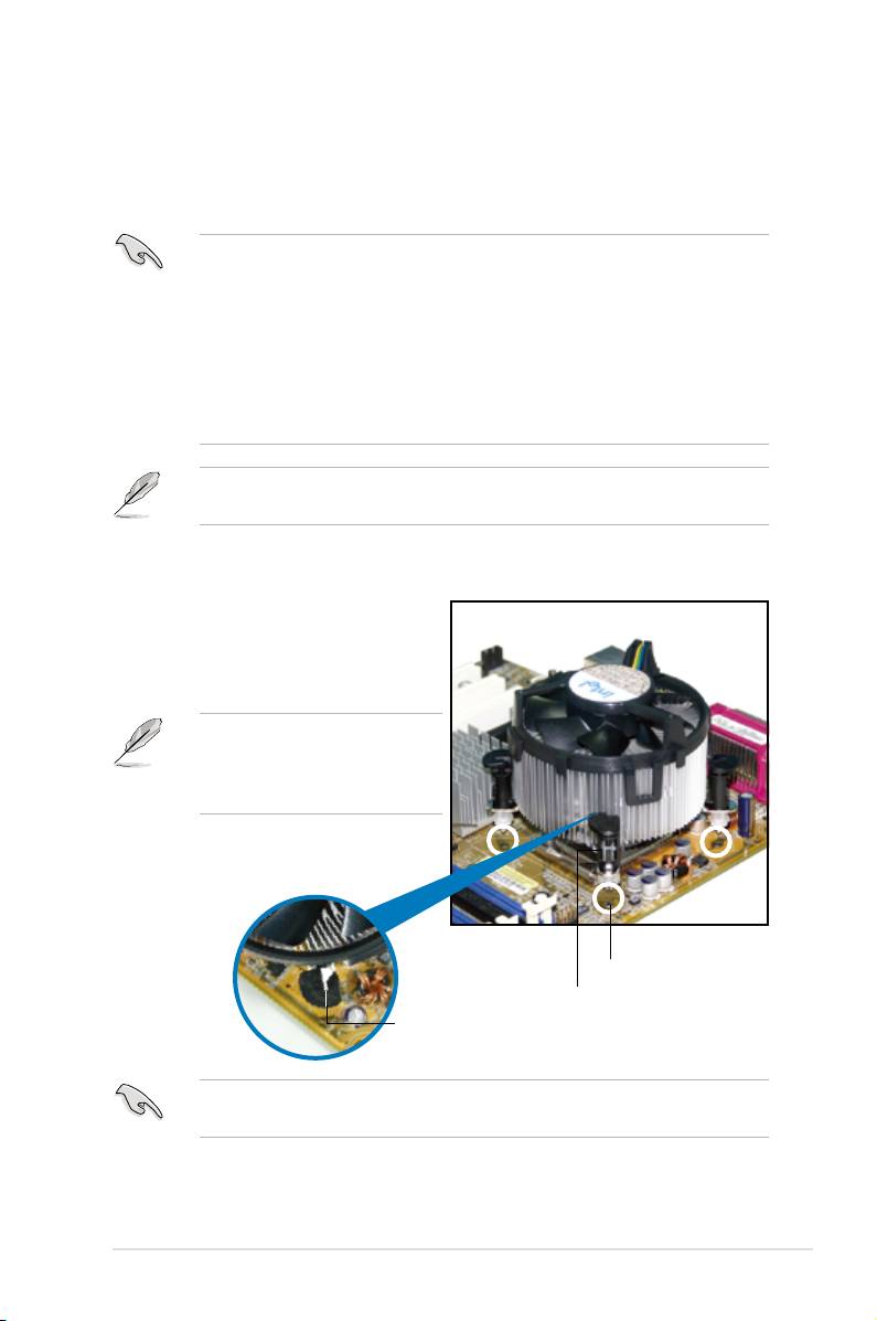
1. Place the heatsink on top of the
installed CPU, making sure that the
four fasteners match the holes on
the motherboard.
Orient the heatsink and fan
assembly such that the CPU fan
cable is closest to the CPU fan
connector.
Motherboard hole
Fastener
Narrow end
of the groove
Make sure to orient each fastener with the narrow end of the groove pointing
outward. (The photo shows the groove shaded for emphasis.)
ASUS P5E3 Premium/WiFi-AP @n 2-9
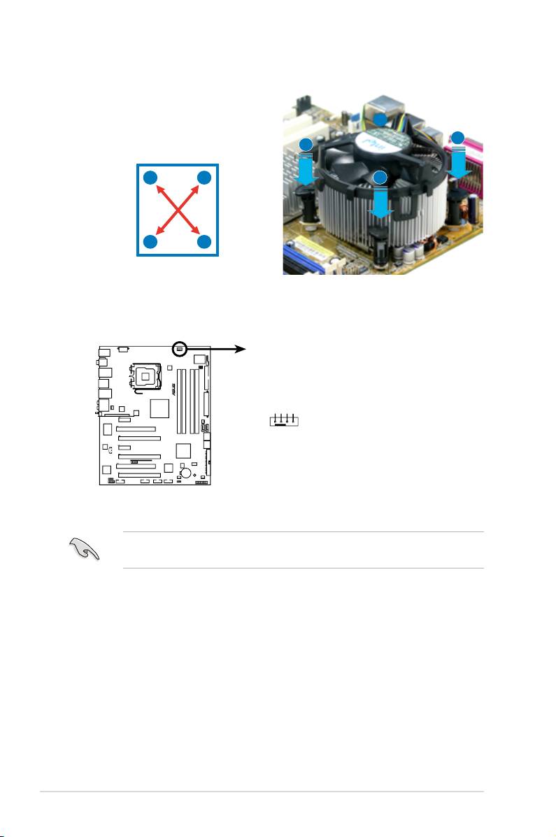
2. Push down two fasteners at a time in
a diagonal sequence to secure the
B
heatsink and fan assembly in place.
A
A
A
B
B
B
A
3. Connect the CPU fan cable to the connector on the motherboard labeled
CPU_FAN.
DO NOT forget to connect the CPU fan connector! Hardware monitoring errors
can occur if you fail to plug this connector.
2-10 Chapter 2: Hardware information
CPU_FAN
®
GND
CPU FAN PWR
CPU FAN IN
CPU FAN PWM
P5E3 PREMIUM
P5E3 Premium/WiFi-AP @n
CPU fan connector
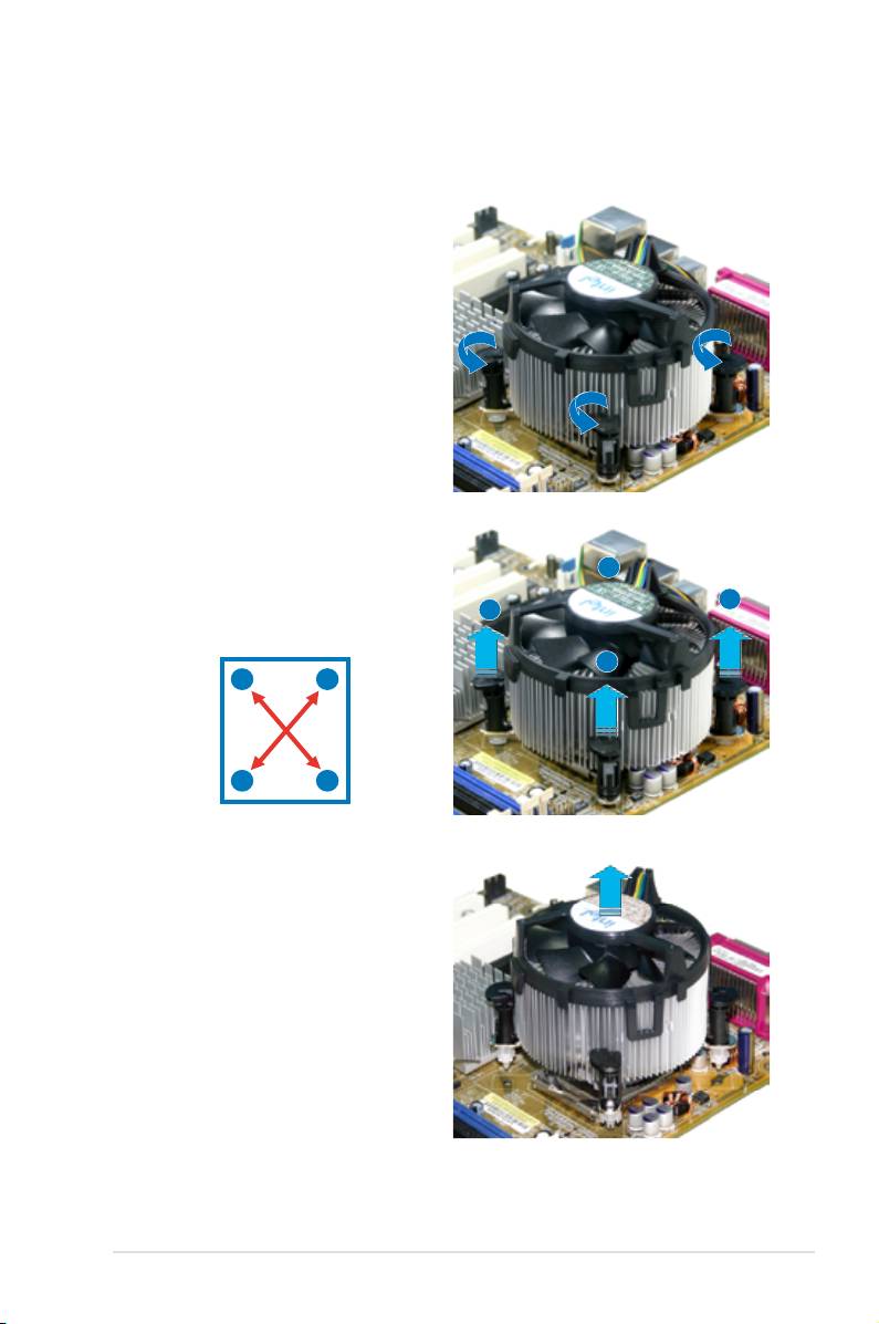
2.3.3 Uninstalling the CPU
heatsink and fan
To uninstall the CPU heatsink and fan:
1. Disconnect the CPU fan cable from
the connector on the motherboard.
2. Rotate each fastener
counterclockwise.
3. Pull up two fasteners at a time in
a diagonal sequence to disengage
B
the heatsink and fan assembly from
the motherboard.
A
A
B
A
B
B
A
4. Carefully remove the heatsink
and fan assembly from the
motherboard.
ASUS P5E3 Premium/WiFi-AP @n 2-11

5. Rotate each fastener clockwise to
ensure correct orientation when
reinstalling.
Narrow end of the groove
The narrow end of the
groove should point outward
after resetting. (The photo
shows the groove shaded for
emphasis.)
Refer to the documentation in the boxed or stand-alone CPU fan package for
detailed information on CPU fan installation.
2-12 Chapter 2: Hardware information
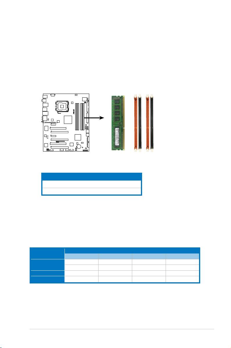
2.4 System memory
2.4.1 Overview
The motherboard comes with four Double Data Rate 3 (DDR3) Dual Inline Memory
Modules (DIMM) sockets.
A DDR3 module has the same physical dimensions as a DDR2 DIMM but is
notched differently to prevent installation on a DDR2 DIMM socket. DDR3 modules
are developed for better performance with less power consumption.
The gure illustrates the location of the DDR3 DIMM sockets:
ASUS P5E3 Premium/WiFi-AP @n 2-13
DIMM_A1
DIMM_A2
DIMM_B1
DIMM_B2
®
P5E3 PREMIUM
P5E3 Premium/WiFi-AP @n
240-pin DDR3 DIMM sockets
Channel Sockets
Channel A DIMM_A1 and DIMM_A2
Channel B DIMM_B1 and DIMM_B2
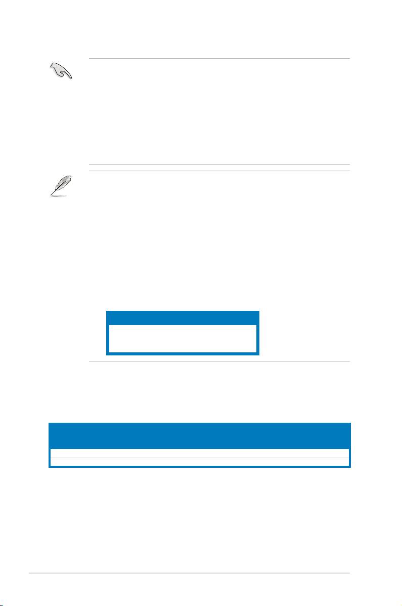
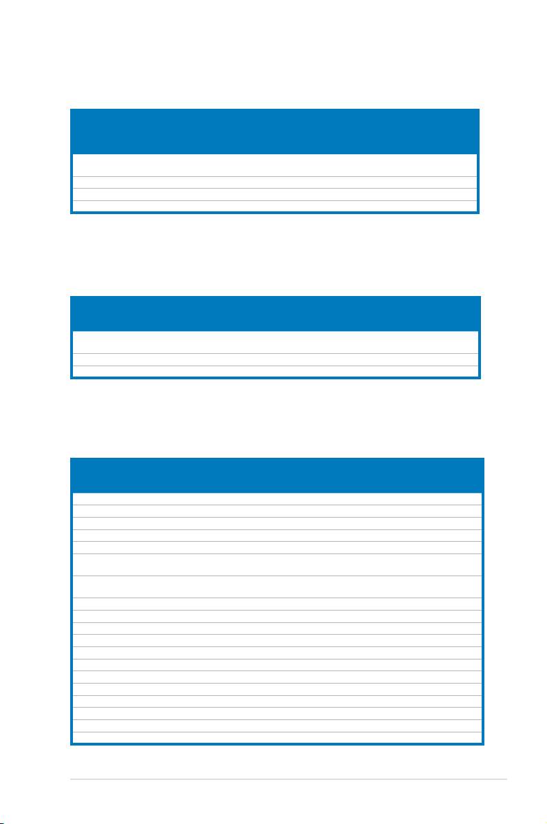
2.4.2 Memorycongurations
You may install 512 MB, 1 GB, and 2 GB unbuffered ECC, non-ECC DDR3 DIMMs
into the DIMM sockets.
Recommendmemoryconguration
Sockets
Mode
DIMM_A1
DIMM_A2 DIMM_B1
DIMM_B2
-
-
- populated
Single-channel
-
populated -
-
Dual-channel (1)
- populated - populated
Dual-channel (2) populated
populated populated
populated
• You may install varying memory sizes in Channel A and Channel B. The
system maps the total size of the lower-sized channel for the dual-channel
conguration. Any excess memory from the higher-sized channel is then
mapped for single-channel operation.
• Always install DIMMs with the same CAS latency. For optimum
compatibility, it is recommended that you obtain memory modules from the
same vendor.
• Due to chipset resource allocation, the system may detect less than 8 GB
system memory when you installed four 2 GB DDR3 memory modules.
• If you install four 1 GB memory modules, the system may detect less than
3 GB of total memory because of address space allocation for other critical
functions. This limitation applies to Windows Vista 32-bit/Windows XP
32-bit version operating system since it does not support PAE (Physical
Address Extention) mode.
• If you install Windows Vista 32-bit/Windows XP 32-bit version operating
system, we recommend that you install less than 3GB of total memory.
Notes on memory limitations
• Due to chipset limitation, this motherboard can only support up to
8 GB on the operating systems listed below. You may install a maximum of
2 GB DIMMs on each slot.
64-bit
Windows XP Professional x64 Edition
Windows Vista x64 Edition
P5E3 Premium/WiFi-AP @n Motherboard Qualied Vendors
Lists (QVL) DDR3-1800MHz capability
DIMM socket support
Chip
SS/
Size Vendor Model CL
Component
(Optional)
Brand
DS
A* B* C*
1GB CORSAIR TWIN3X2048-1800C7DF G 7 Micon SS Heatsink • •
1GB OCZ OCZ3P18002GK 8 Micon SS Heatsink • •
2-14 Chapter 2: Hardware information
P5E3 Premium/WiFi-AP @n Motherboard Qualied Vendors
Lists (QVL) DDR3-1600MHz capability
DIMM socket support
SS/
(Optional)
Size Vendor Chip No. CL Chip Brand
Component
DS
A* B* C*
CM3X1024-
1GB CORSAIR
7 Micon SS Heatsink • •
1600C7DHXIN
1GB OCZ OCZ3P16002GK 7 Micon SS Heatsink • •
1GB A-DATA DDR3-1600X 7 Micon SS Heatsink • •
1GB SuperTalent W1600X2G7 7 Micon SS Heatsink • •
P5E3 Premium/WiFi-AP @n Motherboard Qualied Vendors
Lists (QVL) DDR3-1333MHz capability
DIMM socket
SS/
Size Vendor Chip No. CL Chip Brand
Part No.
support (Optional)
DS
A* B* C*
EBJ51UD8BAFA-
512MB ELPIDA J5308BASE-DG-E 8 ELPIDA SS
• • •
DG-E
1GB SAMSUNG K4B1G0846C-ZCF8 8 SAMSUNG SS M378B2873CZ0-CG9 • •
1GB OCZ Heat-Sink Package 7-7-7-20 N/A DS OCZ3P13332GK • • •
P5E3 Premium/WiFi-AP @n Motherboard Qualied Vendors
Lists (QVL) DDR3-1066MHz capability
DIMM socket
SS/
Size Vendor Chip No. CL Chip Brand
Part No.
support (Optional)
DS
A* B* C*
512MB Qimonda IDSH51-03A1F1C-10F N/A QIMONDA SS IMSH51U03A1F1C-10F • • •
1GB Qimonda IDSH51-03A1F1C-10F N/A QIMONDA DS IMSH1GU13A1F1C-10F • •
512MB ELPIDA J5308BASE-AC-E 8 ELPIDA SS EBJ51UD8BAFA-AG-E • • •
1GB ELPIDA J5308BASE-AC-E 8 ELPIDA DS EBJ11UD8BAFA-AG-E • •
512MB NANYA NT5CB64M8AN-BE N/A NANYA SS NT512C64B88A0NY-BF • • •
MT8JTF12864AY-
1GB MICRON D9GTR 7 MICRON SS
• •
1G1BZES
MT16JTF25664AY-
2GB MICRON Z9HWQ 7 MICRON DS
•
1G1BYES
1GB SAMSUNG K4B1G0846C-ZCF8 7-7-7 SAMSUNG SS M378B2873CZ0-CF8 • •
1GB SAMSUNG K4B1G0846C-ZCG8 8 SAMSUNG SS M378B2873CZ0-CG8 • •
2GB SAMSUNG K4B1G0846C-ZCF8 7 SAMSUNG DS M378B5673CZ0-CF8 •
1GB SAMSUNG K4B1G0846C-ZCF8 7 SAMSUNG SS M391B2873CZ0-CF8 • •
512MB Kingston IDSH51-03A1F1C-10F N/A QIMONDA SS KVR1066D3N7/512 • • •
1GB Kingston J5308BASE-AC-E 7 ELPIDA DS KVR1066D3N7/1G • •
512MB Kingston J5308BASE-AC-E 7 ELPIDA SS KVR1066D3N7/512 • • •
1GB CORSAIR Heat-Sink Package 7 N/A DS CM3X1024-1066C7 • •
1GB Hynix HY5TQ1G831ZNFP-G7 7 HYNIX SS HYMT112U64ZNF8-G7 • •
2GB Hynix HY5TQ1G831ZNFP-G7 7 HYNIX DS HYMT125U64ZNF8-G7 •
512MB GEIL Heat-Sink Package 6 N/A SS G31GB1066C6DC • • •
1GB WINTEC IDSH51-03A1F1C-10F 7 QIMONDA DS 3DU3191A-10 • • •
ASUS P5E3 Premium/WiFi-AP @n 2-15
P5E3 Premium/WiFi-AP @n Motherboard Qualied Vendors
Lists (QVL) DDR3-800MHz capability
DIMM socket
SS/
Size Vendor Chip No. CL Chip Brand
Part No.
support (Optional)
DS
A* B* C*
512MB ELPIDA J5308BASE-AC-E 6 ELPIDA SS EBJ51UD8BAFA-8C-E • • •
1GB ELPIDA J5308BASE-AC-E 6 ELPIDA DS EBJ11UD8BAFA-8C-E • • •
NT512C64B88A0NY-
512MB NANYA NT5CB64M8AN-25D N/A NANYA SS
• • •
25D
NT1GC64B8HA0NY-
1GB NANYA NT5CB64M8AN-25D N/A NANYA DS
• • •
25D
1GB Qimonda IDSH51-03A1F1C-08E N/A QIMONDA DS IMSH1GU13A1F1C-08E • • •
512MB Qimonda IDSH51-03A1F1C-08D N/A Qimonda SS IMSH51U03A1F1C-08D • • •
512MB Qimonda IDSH51-03A1F1C-08E N/A Qimonda SS IMSH51U03A1F1C-08E • • •
1GB Hynix HY5TQ1G831ZNF-S6 N/A Hynix SS HYMT112U64ZNF8-S6 • • •
2GB Hynix HY5TQ1G831ZNF-S5 N/A Hynix DS HYMT125U64ZNF8-S5 • • •
Side(s): SS - Single-sided DS - Double-sided
DIMM support:
A - Supports one module inserted into either slot as Single-channel memory conguration.
B - Supports two modules inserted into either the orange slots or the black slots as one pair of
Dual-channel memory conguration.
C - Supports four modules inserted into both the orange slots and the black slots as two pairs
of Dual-channel memory conguration.
Visit the ASUS website for the latest QVL.
2-16 Chapter 2: Hardware information
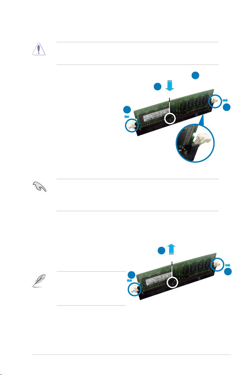
2.4.3 Installing a DIMM
Unplug the power supply before adding or removing DIMMs or other
system components. Failure to do so can cause severe damage to both the
motherboard and the components.
2
To install a DIMM:
3
1. Unlock a DIMM socket by pressing
DDR3 DIMM notch
the retaining clips outward.
2. Align a DIMM on the socket
1
1
such that the notch on the DIMM
matches the break on the socket.
3. Firmly insert the DIMM into the
socket until the retaining clips
snap back in place and the DIMM
is properly seated.
Unlocked retaining clip
• A DDR3 DIMM is keyed with a notch so that it ts in only one direction. DO
NOT force a DIMM into a socket to avoid damaging the DIMM.
• The DDR3 DIMM sockets do not support DDR and DDR2 DIMMs. DO NOT
install DDR or DDR2 DIMMs to the DDR3 DIMM sockets.
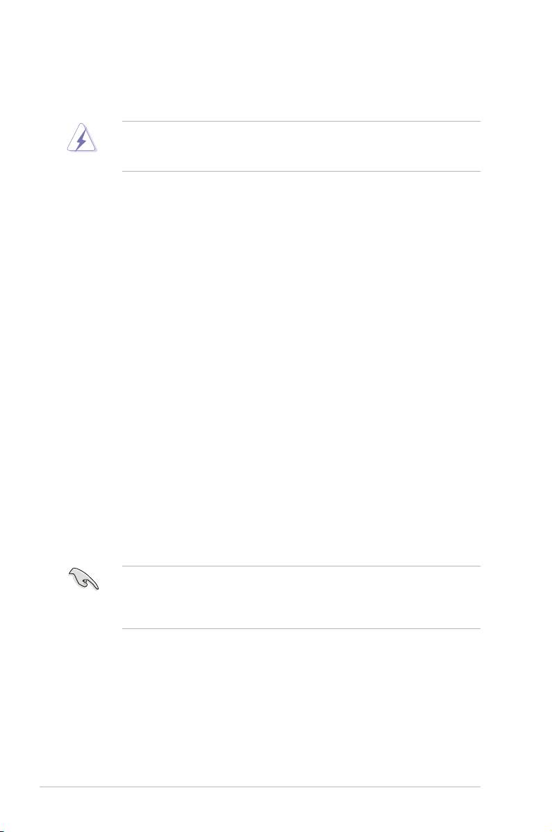
2.4.4 Removing a DIMM
To remove a DIMM:
2
1. Simultaneously press the retaining
DDR3 DIMM notch
clips outward to unlock the DIMM.
1
1
Support the DIMM lightly with
your ngers when pressing the
retaining clips. The DIMM might
get damaged when it ips out
with extra force.
2. Remove the DIMM from the socket.
ASUS P5E3 Premium/WiFi-AP @n 2-17
2.5 Expansion slots
In the future, you may need to install expansion cards. The following sub-sections
describe the slots and the expansion cards that they support.
Make sure to unplug the power cord before adding or removing expansion
cards. Failure to do so may cause you physical injury and damage motherboard
components.
2.5.1 Installing an expansion card
To install an expansion card:
1. Before installing the expansion card, read the documentation that came with
it and make the necessary hardware settings for the card.
2. Remove the system unit cover (if your motherboard is already installed in a
chassis).
3. Remove the bracket opposite the slot that you intend to use. Keep the screw
for later use.
4. Align the card connector with the slot and press rmly until the card is
completely seated on the slot.
5. Secure the card to the chassis with the screw you removed earlier.
6. Replace the system cover.
2.5.2 Conguring an expansion card
After installing the expansion card, congure it by adjusting the software settings.
1. Turn on the system and change the necessary BIOS settings, if any. See
Chapter 4 for information on BIOS setup.
2. Assign an IRQ to the card. Refer to the tables on the next page.
3. Install the software drivers for the expansion card.
When using PCI cards on shared slots, ensure that the drivers support “Share
IRQ” or that the cards do not need IRQ assignments. Otherwise, conicts will
arise between the two PCI groups, making the system unstable and the card
inoperable. Refer to the table on the next page for details.
2-18 Chapter 2: Hardware information
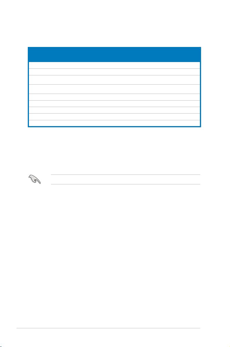
2.5.3 Interrupt assignments
Standard interrupt assignments
IRQ Priority Standard Function
0 1 System Timer
1 2 Keyboard Controller
2 — Re-direct to IRQ#9
3 9 IRQ holder for PCI steering*
4 12 Communications Port (COM1)*
5 13 IRQ holder for PCI steering*
6 14 Floppy Disk Controller
7 15 Printer Port (LPT1)*
8 3 System CMOS/Real Time Clock
9 4 IRQ holder for PCI steering*
10 5 IRQ holder for PCI steering*
11 6 IRQ holder for PCI steering*
12 7 PS/2 Compatible Mouse Port*
13 8 Numeric Data Processor
14 10 Primary IDE Channel
15 11 Secondary IDE Channel
* These IRQs are usually available for PCI devices.
IRQ assignments for this motherboard
A B C D E F G H
PCI slot 1 shared — — — — — — —
PCI slot 2 — shared — — — — — —
LAN (8110SC) shared — — — — — — —
SATA (363) shared — — — — — — —
LAN(8056) — shared — — — — — —
PCIe x16 1 shared — — — — — — —
PCIe x16 2 shared — — — — — — —
PCIe x16 3 — — shared
PCIe x1 1 — — shared — — — — —
PCIe x1 2 — — — shared — — — —
USB controller 1 — — — — — — — shared
USB controller 2 — — — shared — — — —
USB controller 3 — — shared — — — — —
USB controller 4 shared — — — — — — —
USB controller 5 shared — — — — — — —
USB controller 6 shared
USB 2.0 controller 1 — — — — — — — shared
USB 2.0 controller 2 — — shared — — — — —
SATA controller 1 — — shared — — — — —
SATA controller 2 — shared — — — — — —
ASUS P5E3 Premium/WiFi-AP @n 2-19
2.5.4 PCI slots
The PCI slots support cards such as a LAN card, SCSI card, USB card, and other
cards that comply with PCI specications.
2.5.5 PCI Express x1 slots
This motherboard supports PCI Express x1 network cards, SCSI cards and other
cards that comply with the PCI Express specications.
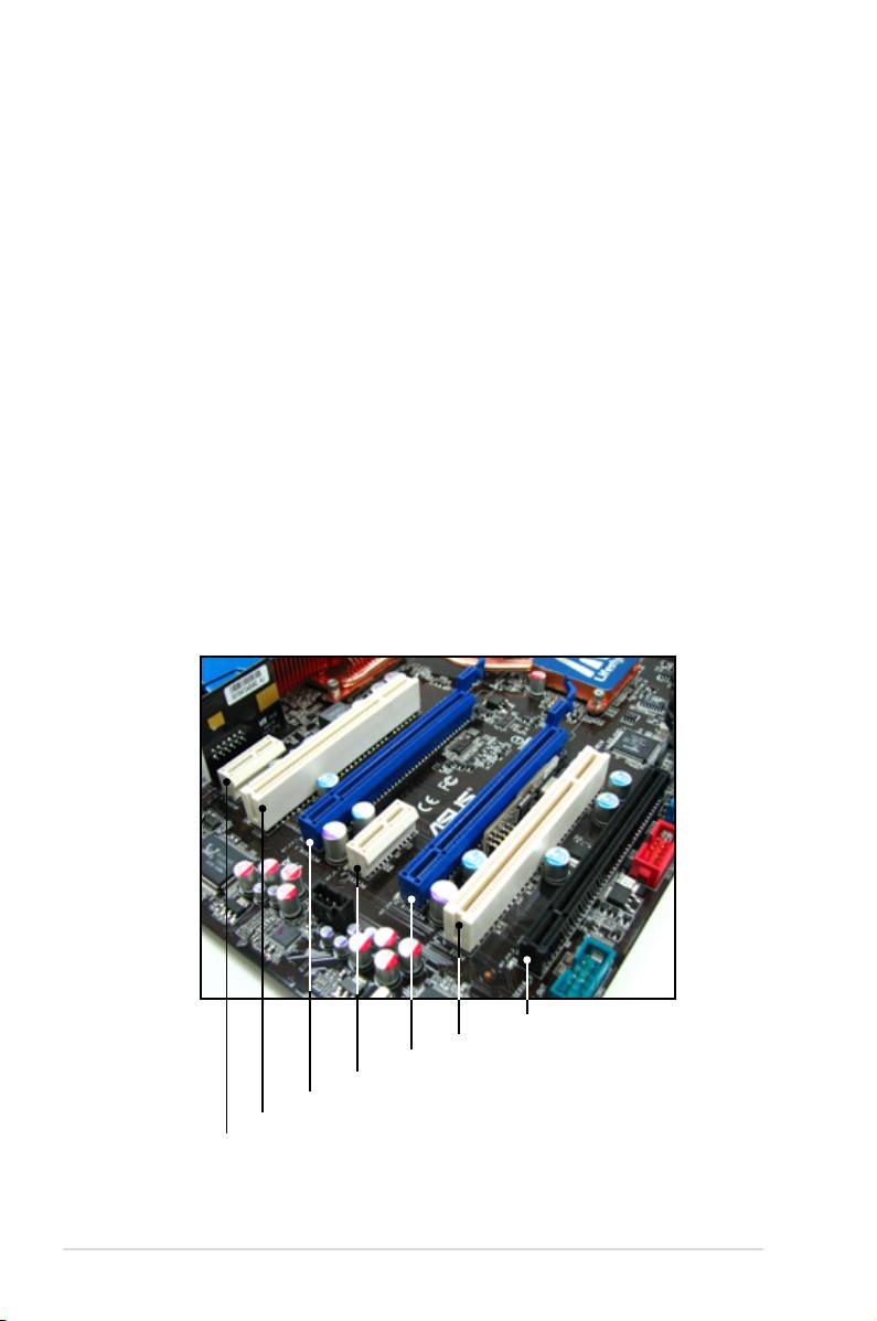
2.5.6 PCI Express 2.0 x16 slots (blue)
This motherboard has two PCI Express 2.0 x16 slots that support PCI Express
2.0 x16 graphic cards complying with the PCI Express specications. With two
graphics cards installed, the motherboard can enable dual-display.
This motherboard supports two ATI CrossFire™ PCI Express 2.0 x16 graphics
cards that comply with the PCI Express specications.
2.5.7 Universal PCI Express x16 slot (black)
This motherboard also supports a Universal PCI Express x16 slot with a maximum
speed of x4 or x1 link. The operating frequency of this slot changes depending on
the type of PCI Express card you install.
PCIe x16_3 slot (black, @x4 or x1)
PCI slot 2
PCIe 2.0 x16_2 slot (blue, @x16)
PCI Express x1_2 slot
PCIe 2.0 x16_1 slot (blue, @x16)
PCI slot 1
PCI Express x1_1 slot
2-20 Chapter 2: Hardware information
• If you install two VGA cards, we recommend that you plug the rear chassis
fan cable to the motherboard connector labeled CHA_FAN3 or CHA_FAN4
for better thermal environment. See page 2-32 for the connector location.
• Some PCI Express devices cannot operate on x4/x1 mode.
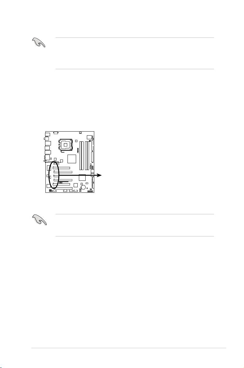
2.5.8 AI Slot Detector
This motherboard comes with on-board LEDs that light up when the PCIE/
PCI devices are not correctly installed. This is a reminder that you should
reinstall these devices. Refer to the gure below for the location of the LEDs.
When the AI Slot Detector lights up for incorrect installation, make sure to shut
down the power supply unit before reinstalling the card to avoid electrical shock
hazard.
ASUS P5E3 Premium/WiFi-AP @n 2-21
®
DET_X1_1
DET_PCI1
P5E3 PREMIUM
DET_X16_1
DET_X1_2
DET_X16_2
DET_PCI2
DET_X16_3
P5E3 Premium/WiFi-AP @n
Slot Detector
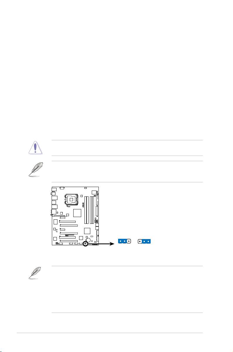
2.6 Jumpers
1. Clear RTC RAM (CLRTC)
This jumper allows you to clear the Real Time Clock (RTC) RAM in CMOS.
You can clear the CMOS memory of date, time, and system setup parameters
by erasing the CMOS RTC RAM data. The onboard button cell battery
powers the RAM data in CMOS, which include system setup information such
as system passwords.
To erase the RTC RAM:
1. Turn OFF the computer and unplug the power cord.
2. Move the jumper cap from pins 1-2 (default) to pins 2-3. Keep the cap on
pins 2-3 for about 5~10 seconds, then move the cap back to pins 1-2.
3. Plug the power cord and turn ON the computer.
4. Hold down the <Del> key during the boot process and enter BIOS setup
to re-enter data.
Except when clearing the RTC RAM, never remove the cap on CLRTC jumper
default position. Removing the cap will cause system boot failure!
• You do not need to clear the RTC when the system hangs due to
overclocking. For system failure due to overclocking, use the C.P.R. (CPU
Parameter Recall) feature. Shut down and reboot the system so the BIOS
can automatically reset parameter settings to default values.
• Due to the chipset behavior, AC power off is required to enable C.P.R.
function. You must turn off and on the power supply or unplug and plug the
power cord before rebooting the system.
2-22 Chapter 2: Hardware information
®
P5E3 PREMIUM
CLRTC
1 2 2 3
Normal Clear RTC
P5E3 Premium/WiFi-AP @n
(Default)
Clear RTC RAM
If the steps above do not help, remove the onboard battery and move the
jumper again to clear the CMOS RTC RAM data. After the CMOS clearance,
reinstall the battery.
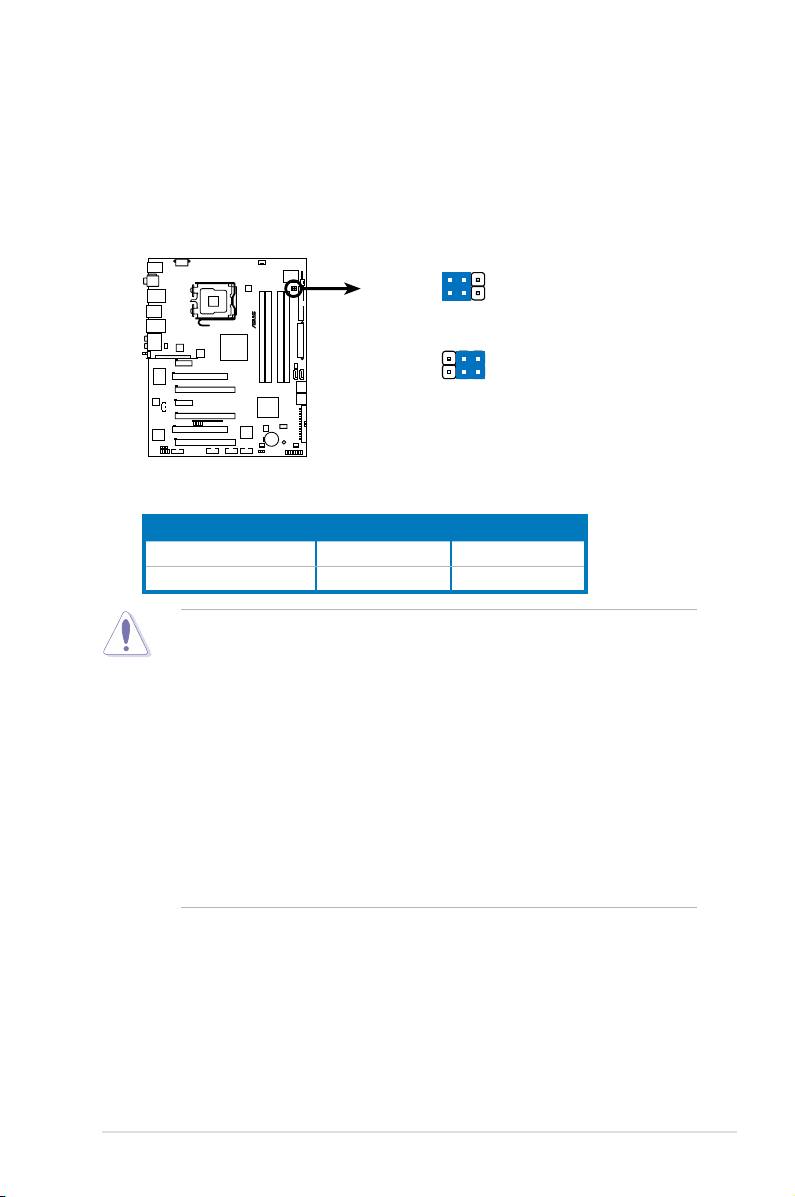
2. CPU / Northbridge overvoltage setting (3-pin OV_CPU, 3-pin OV_NB)
These jumpers allow you to enable or disable the advanced CPU and
Northbridge overvoltage settings in BIOS. Read the following information
before you change the jumper settings. Set to pins 1-2 to activate the
advanced CPU / Northbridge overvoltage feature.
ASUS P5E3 Premium/WiFi-AP @n 2-23
1 2
OV_CPU
OV_NB
®
Enable OV
2 3
OV_CPU
OV_NB
P5E3 PREMIUM
Normal
(Default)
P5E3 Premium/WiFi-AP @n
CPU/Northbridge overvoltage setting
OV_CPU OV_NB
Pins 2-3 (Default) up to 1.70V up to 1.91V
Pins 1-2 (OV Enabled) up to 2.10V up to 2.21V
• Before you change the jumper settings for extra-high overvoltage ability,
use the BIOS items introduced in 4.4 Ai Tweaker rst to adjust the desired
CPU and Northbridge performance. Make sure your system function well
under the highest BIOS voltage settings before you change the setting of
these two jumpers.
• Refer to
4.4 Ai Tweaker for more information about CPU and Northbridge
overvoltage settings.
• DO NOT set the OV_CPU jumper to pins 1-2 when you install a new CPU
and have not booted for the rst time. Doing so may cause the system to
halt. For system failure due to the wrong setting of the OV_CPU jumper,
shut down the computer and move the cap back to pins 2-3.
• The system may need a better cooling system (for example, a water-
cooling system) to work stably under high voltage settings.
2.7 Connectors
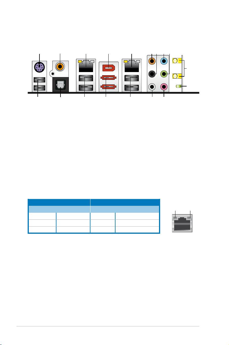
2.7.1 Rear panel connectors
1. PS/2 keyboard port (purple). This port is for a PS/2 keyboard.
2. Coaxial S/PDIF Out port.
This port connects an external audio output device
via a coaxial S/PDIF cable.
®
3. LAN 1 (RJ-45) port.
This Marvell
LAN port allows Gigabit connection to a
Local Area Network (LAN) through a network hub. Refer to the table below
for the LAN port LED indications.
4. IEEE 1394a port.
This 6-pin IEEE 1394a port provides high-speed
connectivity for audio/video devices, storage peripherals, PCs, or portable
devices.
®
5. LAN 2 (RJ-45) port.
This Realtek
LAN port allows Gigabit connection to a
Local Area Network (LAN) through a network hub. Refer to the table below
for the LAN port LED indications.
LAN port LED indications
Activity Link LED Speed LED
ACT/LINK
SPEED
LED
LED
Status Description Status Description
OFF No link OFF 10 Mbps connection
ORANGE Linked ORANGE 100 Mbps connection
BLINKING Data activity GREEN 1 Gbps connection
LAN port
6. Center/Subwoofer port (orange).
This port connects the center/subwoofer
speakers.
7. Rear Speaker Out port (black).
This port connects the rear speakers in a
4-channel, 6-channel, or 8-channel audio conguration..
8. Line In port (light blue).
This port connects the tape, CD, DVD player, or
other audio sources.
9. Line Out port (lime).
This port connects a headphone or a speaker. In
4-channel, 6-channel, and 8-channel conguration, the function of this port
becomes Front Speaker Out.
2-24 Chapter 2: Hardware information
1 54 6
2
3
8 97
10
11
17 14
1618
15 1213
10. Wireless LAN ports. These ports are on the onboard wireless LAN module
that allow you to set up a wireless network and exchange information
with other wireless devices without tagling cables and wires. Connect the
moveable omni-directional antennas to these ports.
11. Wireless LAN Activity LED
. The wireless module comes with an activity
LED.
12. Microphone port (pink).
This port connects a microphone.
13. Side Speaker Out port (gray).
This port connects the side speakers in an
8-channel audio conguration.
Refer to the audio conguration table below for the function of the audio ports in
2, 4, 6, or 8-channel conguration.
Audio 2, 4, 6, or 8-channel conguration
Port Headset
4-channel 6-channel 8-channel
2-channel
Light Blue Line In Line In Line In Line In
Lime Line Out Front Speaker Out Front Speaker Out Front Speaker Out
Pink Mic In Mic In Mic In Mic In
Orange – – Center/Subwoofer Center/Subwoofer
Black – Rear Speaker Out Rear Speaker Out Rear Speaker Out
Gray – – – Side Speaker Out
14. USB 2.0 ports 1 and 2.
These 4-pin Universal Serial Bus (USB) ports are
available for connecting USB 2.0 devices.
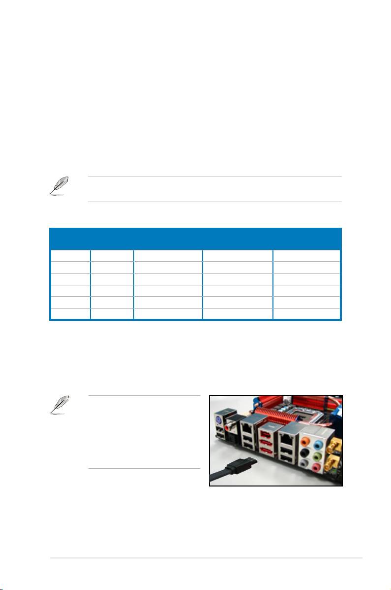
15. External SATA port 1/2. These port connect to an external a Serial ATA hard
disk drive. To congure a RAID0 or RAID1, connect external Serial ATA hard
disk drives to the External SATA port 1 and 2.
The external SATA port supports
external SATA 3 Gb/s devices.
Longer cables support higher
power requirements to deliver
signal up to two meters away,
and enables improved hot-swap
function.
ASUS P5E3 Premium/WiFi-AP @n
2-25
• Before creating a RAID set using Serial ATA hard disks, make sure that you
have connected the Serial ATA signal cable and installed Serial ATA hard
disk drives; otherwise, you cannot enter the JMicron RAID utility and SATA
BIOS setup during POST.
• If you intend to create a RAID conguration using this connector, set the
J-Micron eSATA/PATA Controller Mode in the BIOS to [RAID]. See section
4.5.3 Onboard Device Conguration for details.
• When using hot-plug and NCQ, set the J-Micron eSATA/PATA Controller
Mode in the BIOS to [AHCI]. See section 4.5.3 Onboard Device
Conguration for details.
®
• Before creating a RAID set, refer to
5.4.4 JMicron
RAID Conguration or
the manual bundled in the motherboard support DVD.
• DO NOT insert different connectors to the external SATA ports.
• DO NOT unplug the external Serial ATA box when a RAID 0 or RAID 1 is
congured.
16. USB 2.0 ports 3 and 4. These 4-pin Universal Serial Bus (USB) ports are
available for connecting USB 2.0 devices.
17. Optical S/PDIF Out port
. This port connects an external audio output device
via an optical S/PDIF cable.
18. USB 2.0 ports 5 and 6.
These 4-pin Universal Serial Bus (USB) ports are
available for connecting USB 2.0 devices.
2-26 Chapter 2: Hardware information
2.7.2 Internal connectors
1. Floppy disk drive connector (34-1 pin FLOPPY)
This connector is for the provided oppy disk drive (FDD) signal cable. Insert
one end of the cable to this connector, then connect the other end to the
signal connector at the back of the oppy disk drive.
Pin 5 on the connector is removed to prevent incorrect cable connection when
using a FDD cable with a covered Pin 5.
ASUS P5E3 Premium/WiFi-AP @n
2-27
FLOPPY
®
NOTE: Orient the red markings on
the floppy ribbon cable to PIN 1.
P5E3 PREMIUM
PIN 1
P5E3 Premium/WiFi-AP @n
Floppy disk drive connector
2. IDE connector (40-1 pin PRI_E IDE)
The onboard IDE connector is for the Ultra DMA 133/100/66 signal cable.
There are three connectors on each Ultra DMA 133/100/66 signal cable:
blue, black, and gray. Connect the blue connector to the motherboard’s IDE
connector, then select one of the following modes to congure your device.
Drive jumper setting Mode of
Cable connector
device(s)
Single device Cable-Select or Master - Black
Black
Two devices Cable-Select Master
Slave Gray
Master Master Black or gray
Slave Slave
• Pin 20 on the IDE connector is removed to match the covered hole on the
Ultra DMA cable connector. This prevents incorrect insertion when you
connect the IDE cable.
• Use the 80-conductor IDE cable for Ultra DMA 133/100/66 IDE devices.
If any device jumper is set as “Cable-Select,” make sure all other device
jumpers have the same setting.
2-28 Chapter 2: Hardware information
®
PRI_EIDE
NOTE: Orient the red markings
P5E3 PREMIUM
(usually zigzag) on the IDE
ribbon cable to PIN 1.
P5E3 Premium/WiFi-AP @n
IDE connector

3. ICH9R Serial ATA connectors (7-pin SATA 1-6 [red])
These connectors are for the Serial ATA signal cables for Serial ATA hard disk
drives.
If you installed Serial ATA hard disk drives, you can create a RAID 0, 1, 5,
®
and 10 conguration with the Intel
Matrix Storage Technology through the
®
onboard Intel
ICH9R RAID controller.
ASUS P5E3 Premium/WiFi-AP @n
2-29
SATA1
GND
GND
SATA2
RSATA_TXP1
RSATA_TXP2
RSATA_TXN1
RSATA_TXN2
GND
GND
RSATA_RXP1
RSATA_RXP2
RSATA_RXN1
RSATA_RXN2
®
GND
GND
SATA3
GND
GND
SATA4
RSATA_TXP3
RSATA_TXP4
RSATA_TXN3
RSATA_TXN4
GND
GND
RSATA_RXP3
RSATA_RXP4
RSATA_RXN3
RSATA_RXN4
P5E3 PREMIUM
GND
GND
SATA5
GND
GND
SATA6
RSATA_TXP5
RSATA_TXP6
RSATA_TXN5
RSATA_TXN6
GND
GND
RSATA_RXP5
RSATA_RXP6
RSATA_RXN5
RSATA_RXN6
GND
GND
P5E3 Premium/WiFi-AP @n
SATA connectors
•
These connectors are set to Standard IDE mode by default. In Standard
IDE mode, you can connect Serial ATA boot/data hard disk drives to these
connectors. If you intend to create a Serial ATA RAID set using these
connectors, set the Congure SATA as item in the BIOS to [RAID]. See
section 4.3.6 SATA Conguration for details.
• Before creating a RAID set, refer to
5.4.3 Intel RAID Conguration or the
manual bundled in the motherboard support CD.
®
•
You must install the Windows
XP Service Pack 1 before using Serial ATA
hard disk drives. The Serial ATA RAID feature (RAID 0, 1, 5 and 10) is
®
available only if you are using Windows
XP or later version.
•
When using the connectors in Standard IDE mode, connect the primary
(boot) hard disk drive to the SATA1/2/5 connector.
•
When using hot-plug and NCQ, set the Congure SATA as in the BIOS to
[AHCI]. See section 4.3.6 SATA Conguration for details.
right angle side
Connect the right-angle side of SATA
signal cable to SATA device. Or you may
connect the right-angle side of SATA
cable to the onboard SATA port to avoid
mechanical conict with huge graphics
cards.
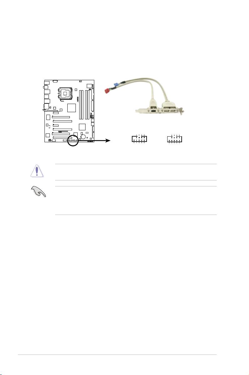
4. USB connectors (10-1 pin USB 78, USB 1112)
These connectors are for USB 2.0 ports. Connect the USB module cable
to any of these connectors, then install the module to a slot opening at the
back of the system chassis. These USB connectors comply with USB 2.0
specication that supports up to 480 Mbps connection speed.
Never connect a 1394 cable to the USB connectors. Doing so will damage the
motherboard!
If your chassis suppots front panel USB ports, you can attach a front panel
USB cable to these connectors. Connect the USB cable to ASUS Q-Connector
(USB, blue) rst, and then install the Q-Connector (USB) to the USB connector
onboard.
2-30 Chapter 2: Hardware information
®
P5E3 PREMIUM
USB_P11+
USB_P11-
USB_P7+
USB+5V
USB_P7-
USB+5V
GND
GND
USB1112 USB78
NC
GND
USB_P12+
USB_P12-
USB+5V
NC
GND
USB_P8+
USB_P8-
USB+5V
P5E3 Premium/WiFi-AP @n
USB 2.0 connectors
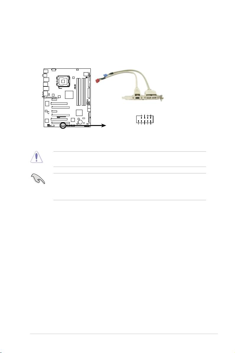
5. IEEE 1394a port connector (10-1 pin IE1394_2)
This connector is for a IEEE 1394a port. Connect the IEEE 1394a module
cable to this connector, then install the module to a slot opening at the back
of the system chassis.
ASUS P5E3 Premium/WiFi-AP @n
2-31
®
P5E3 PREMIUM
+12V
TPB1+
GND
TPA1+
PIN 1
IE1394_2
P5E3 Premium/WiFi-AP @n
GND
+12V
GND
TPB1-
TPA1-
IEEE 1394a connector
Never connect a USB cable to the IEEE 1394a connector. Doing so will damage
the motherboard!
You can attach a FireWire/1394 cable to this connector if your chassis suppots
the front panel IEEE1394 port. Connect the 1394 cable to ASUS Q-Connector
(1394, red) rst, and then install the Q-Connector (1394) to the 1394 connector
onboard.
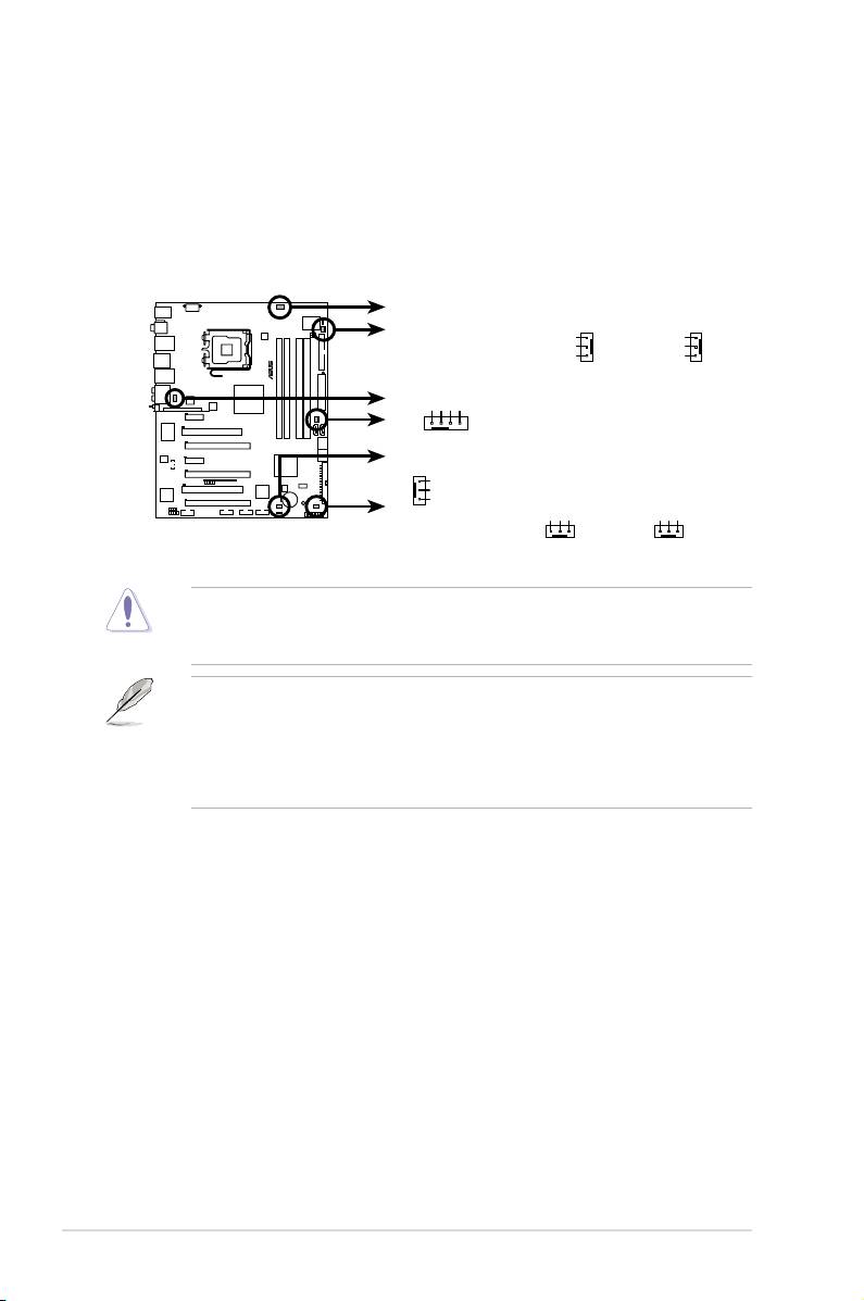
6. CPU, chassis and power fan connectors
(4-pin CPU_FAN, 3-pin CHA_FAN1-4, 3-pin PWR_FAN)
The fan connectors support cooling fans of 350 mA ~ 2000 mA (24 W max.)
or a total of 1 A ~ 7 A (84 W max.) at +12V. Connect the fan cables to the
fan connectors on the motherboard, making sure that the black wire of each
cable matches the ground pin of the connector.
DO NOT forget to connect the fan cables to the fan connectors. Insufcient air
ow inside the system may damage the motherboard components. These are
not jumpers! Do not place jumper caps on the fan connectors!
• Only the CPU-FAN and CHA-FAN 1-4 connectors support the ASUS
Advanced Q-Fan feature.
• If you install two VGA cards, we recommend that you plug the rear chassis
fan cable to the motherboard connector labled CHA_FAN3 or CHA_FAN4
for better themal environment.
2-32 Chapter 2: Hardware information
CPU_FAN
PWR_FAN
CHA_FAN2
Rotation
Rotation
+12V
+12V
®
GND
GND
GND
CPU FAN PWR
CPU FAN IN
CPU FAN PWM
P5E3 PREMIUM
CHA_FAN1
CHA_FAN3 CHA_FAN4
GND
+12V
Rotation
GND
+12V
Rotation
GND
+12V
Rotation
P5E3 Premium/WiFi-AP @n
Fan connectors
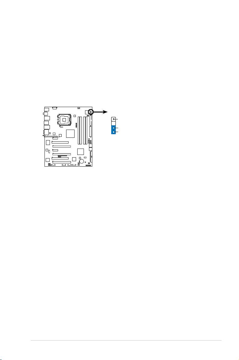
7. Chassis intrusion connector (4-1 pin CHASSIS)
This connector is for a chassis-mounted intrusion detection sensor or switch.
Connect one end of the chassis intrusion sensor or switch cable to this
connector. The chassis intrusion sensor or switch sends a high-level signal to
this connector when a chassis component is removed or replaced. The signal
is then generated as a chassis intrusion event.
By default , the pin labeled “Chassis Signal” and “Ground” are shorted with
a jumper cap. Remove the jumper caps only when you intend to use the
chassis intrusion detection feature.
ASUS P5E3 Premium/WiFi-AP @n 2-33
CHASSIS
+5VSB_MB
®
Chassis Signal
(Default)
GND
P5E3 PREMIUM
P5E3 Premium/WiFi-AP @n
Chassis intrusion connector
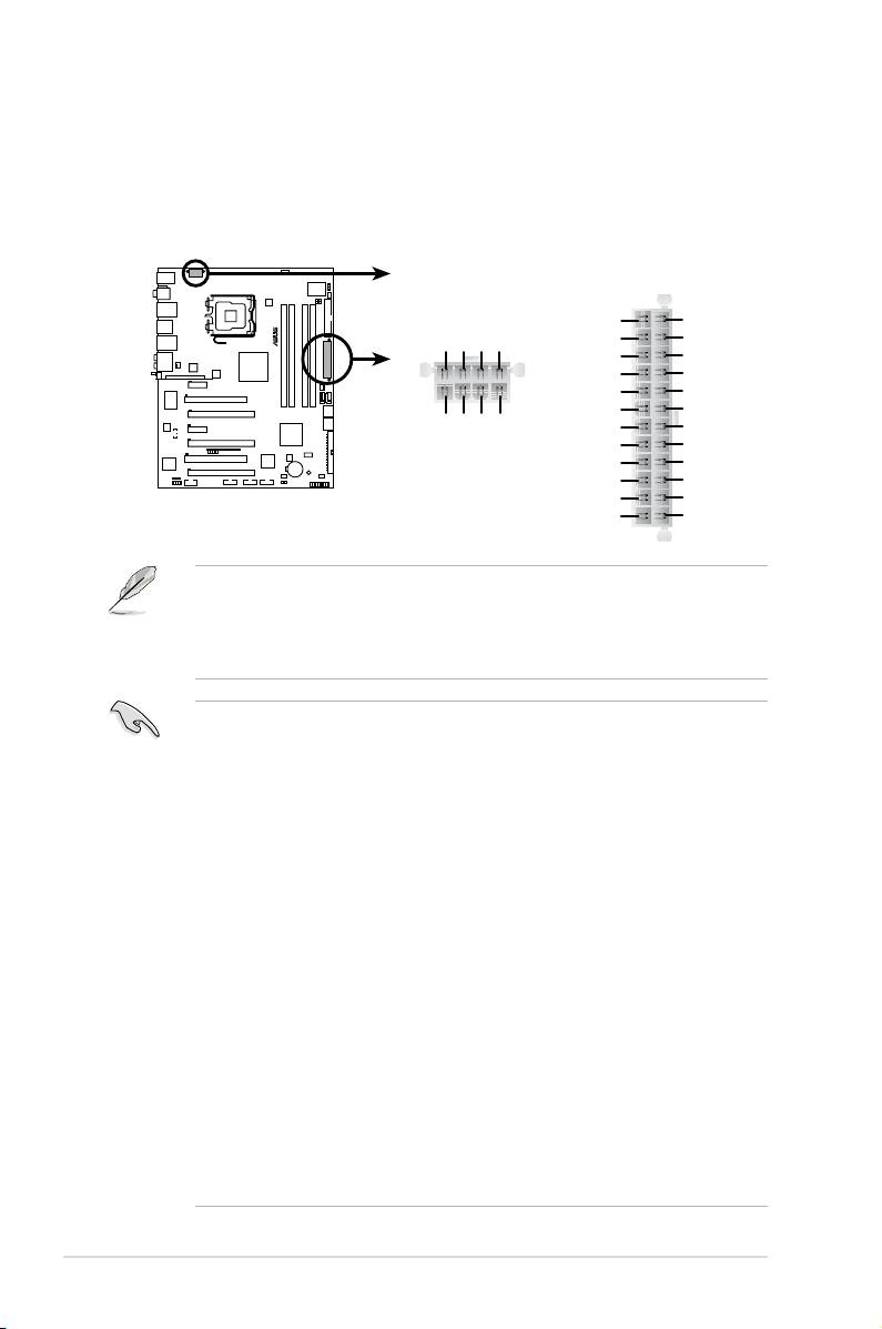
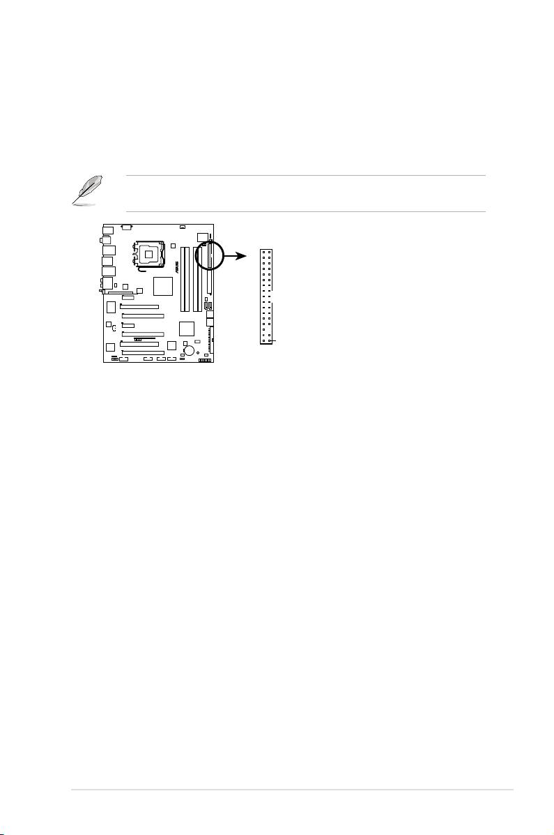
8. ATX power connectors (24-pin EATXPWR, 2x4-pin EATX12V)
These connectors are for ATX power supply plugs. The power supply plugs
are designed to t these connectors in only one orientation. Find the proper
orientation and push down rmly until the connectors completely t.
• Make sure to remove the cap on the EATX12V connector before connecting
an 8-pin EPS +12V power plug.
• Use only either a 4-pin ATX12V or an 8-pin EPS +12V power plug for the
EATX12V connector.
• For a fully congured system, we recommend that you use a power supply
unit (PSU) that complies with ATX 12 V Specication 2.0 (or later version)
and provides a minimum power of 400 W.
• Do not forget to connect the 8-pin / 4-pin EATX12V power plug; otherwise,
the system will not boot.
• Use of a PSU with a higher power output is recommended when
conguring a system with more power-consuming devices. The system
may become unstable or may not boot up if the power is inadequate.
• If you want to use two high-end PCI Express x16 cards, use a PSU with
500W to 600W power or above to ensure the system stability.
• If you are uncertain about the minimum power supply requirement for your
system, refer to the Recommended Power Supply Wattage Calculator
at http://support.asus.com/PowerSupplyCalculator/PSCalculator.
aspx?SLanguage=en-us for details.
• The ATX 12 V Specication 2.0-compliant (400W) PSU has been tested
to support the motherboard power requirements with the following
conguration:
®
®
CPU: Intel
Pentium
Extreme 3.73GHz
Memory: 512 MB DDR3 (x4)
Graphics card: ASUS EAX1900XT
Parallel ATA device: IDE hard disk drive
Serial ATA device: SATA hard disk drive (x2)
Optical drive: DVD-RW
2-34 Chapter 2: Hardware information
EATXPWREATX12V
®
+3 Volts
Ground
+12 Volts
+5 Volts
+12 Volts
+5 Volts
+5V Standby
+5 Volts
Power OK
-5 Volts
P5E3 PREMIUM
Ground
Ground
+5 Volts
Ground
GND +12V DC
GND +12V DC
GND +12V DC
GND +12V DC
Ground
Ground
+5 Volts
PSON#
Ground
Ground
+3 Volts
-12 Volts
P5E3 Premium/WiFi-AP @n
+3 Volts
+3 Volts
ATX power connectors
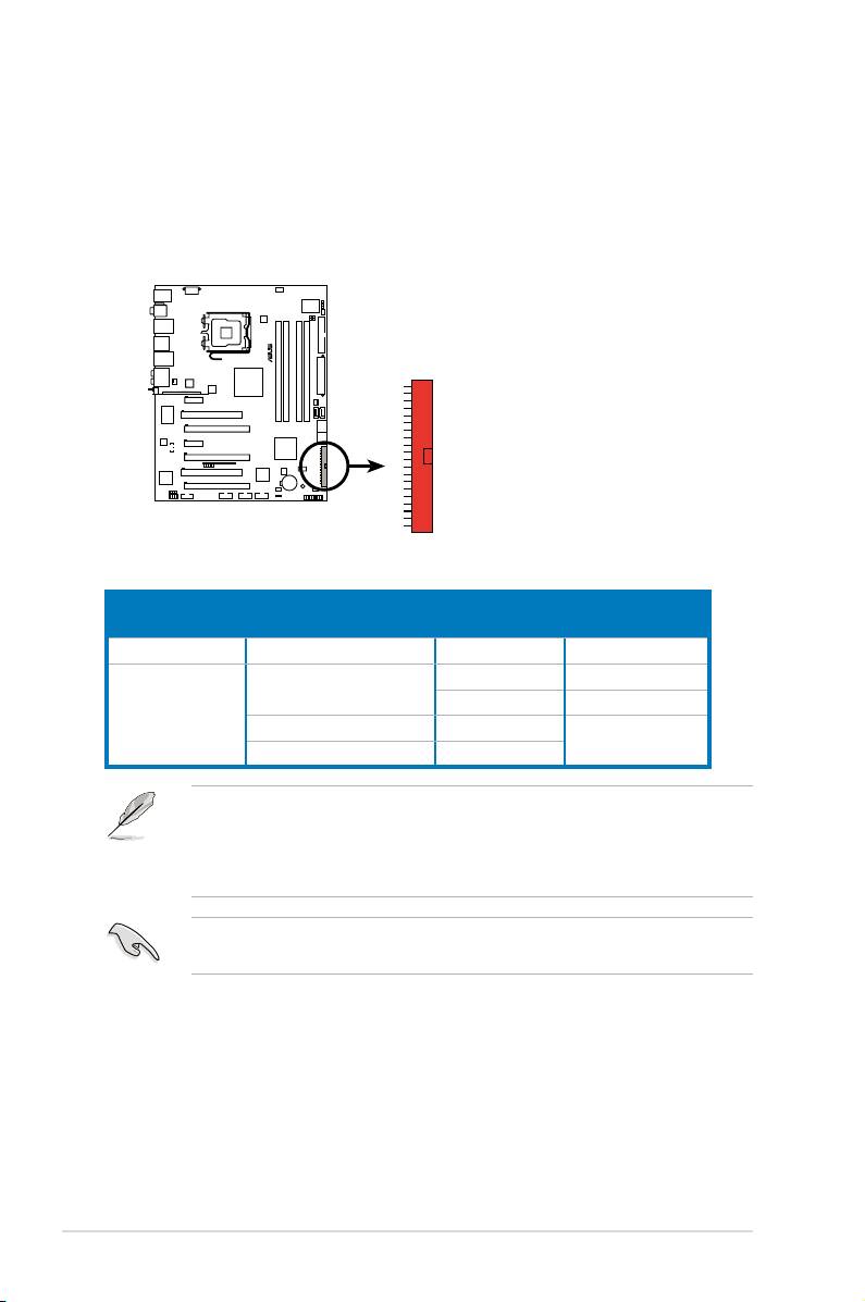
9. Front panel audio connector (10-1 pin AAFP)
This connector is for a chassis-mounted front panel audio I/O module that
supports either HD Audio or legacy AC`97 audio standard. Connect one end
of the front panel audio I/O module cable to this connector.
ASUS P5E3 Premium/WiFi-AP @n 2-35
AAFP
HD Audio-compliant
Legacy AC ‘97 audio
pin definition
pin definition
®
SENSE1_RETUR
SENSE2_RETUR
AGND
GND
NC
NC
P5E3 PREMIUM
PORT1 L
PORT1 RPRESENCE#
PORT2 R
SENSE_SEND
PORT2 L
MIC2
MICPWRNC
Line out_R
NC
Line out_L
P5E3 Premium/WiFi-AP @n
Analog front panel connector
•
We recommend that you connect a high-denition front panel audio
module to this connector to avail of the motherboard’s high-denition audio
capability.
•
If you want to connect a high-denition front panel audio module to this
connector, make sure that the Front Panel Type item in the BIOS is set to
[HD Audio]. If you want to connect an AC' 97 front panel audio module to
this connector, set the item to [AC97]. Refer to page 4-27 for details.
10. Optical drive audio connector (4-pin CD)
This connector allows you to receive stereo audio input from sound sources
such as a CD-ROM, TV tuner, or MPEG card.
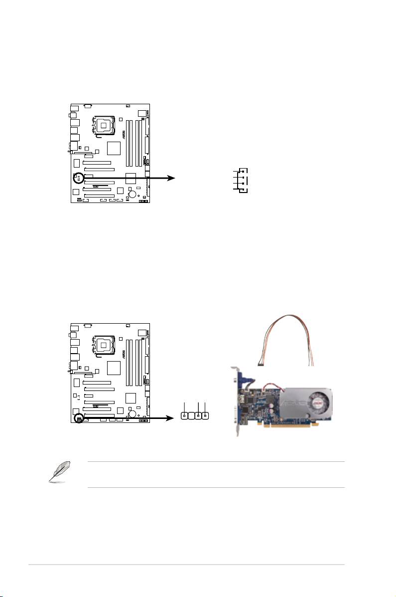
11. Digital audio connector (4-1 pin SPDIF, for ASUS HDMI VGA card)
This connector is for an additional Sony/Philips Digital Interface (S/PDIF)
port(s). If you are using ASUS HDMI-equipped graphics card, connect the
HDMI card to this connector with a S/PDIF out cable.
The ASUS HDMI-equipped graphics card and S/PDIF out cable are purchased
separately.
2-36 Chapter 2: Hardware information
®
CD
P5E3 PREMIUM
Left Audio Channel
Ground
Ground
Right Audio Channel
P5E3 Premium/WiFi-AP @n
Internal audio connector
®
SPDIF_OUT
P5E3 PREMIUM
+5V
SPDIFOUT
GND
P5E3 Premium/WiFi-AP @n
Digital audio connector
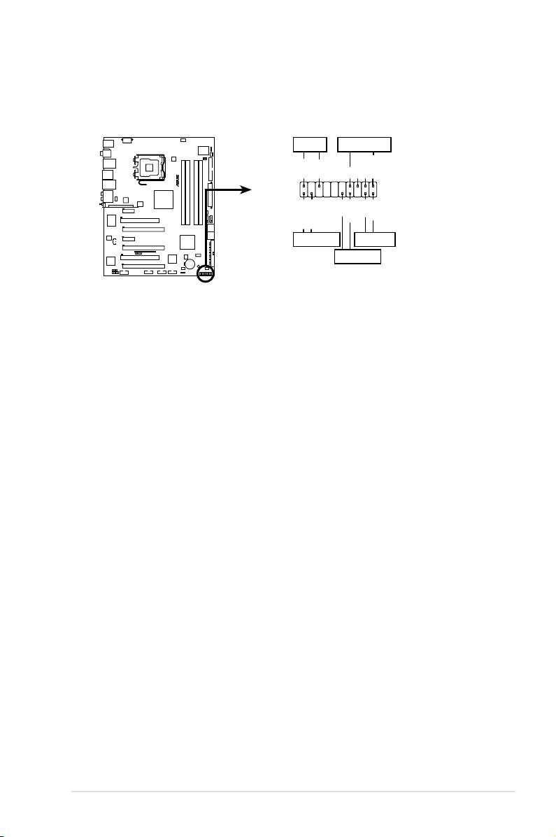
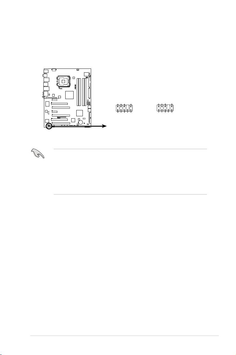
12. System panel connector (20-8 pin PANEL)
This connector supports several chassis-mounted functions.
•
System power LED (2-pin PLED)
This 2-pin connector is for the system power LED. Connect the chassis
power LED cable to this connector. The system power LED lights up when
you turn on the system power, and blinks when the system is in sleep mode.
•
Hard disk drive activity LED (2-pin IDE_LED)
This 2-pin connector is for the HDD Activity LED. Connect the HDD Activity
LED cable to this connector. The IDE LED lights up or ashes when data is
read from or written to the HDD.
•
System warning speaker (4-pin SPEAKER)
This 4-pin connector is for the chassis-mounted system warning speaker. The
speaker allows you to hear system beeps and warnings.
•
ATX power button/soft-off button (2-pin PWRSW)
This connector is for the system power button. Pressing the power button
turns the system on or puts the system in sleep or soft-off mode depending
on the BIOS settings. Pressing the power switch for more than four seconds
while the system is ON turns the system OFF.
•
Reset button (2-pin RESET)
This 2-pin connector is for the chassis-mounted reset button for system
reboot without turning off the system power.
ASUS P5E3 Premium/WiFi-AP @n 2-37
PLED SPEAKER
®
PLED+
PLED-
+5V
Ground
Ground
Speaker
PANEL
PWR
Reset
Ground
Ground
P5E3 PREMIUM
IDE_LED+
IDE_LED-
IDE_LED
RESET
PWRSW
*
Requires an ATX power supply.
P5E3 Premium/WiFi-AP @n
System panel connector
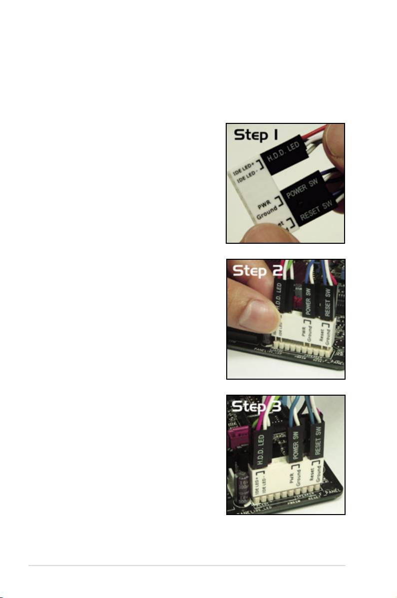
13. ASUS Q-Connector (system panel)
You can use the ASUS Q-Connector to connect/disconnect chassis front
panel cables in a few steps. Refer to the instructions below to install the
ASUS Q-Connector.
1. Connect the front panel cables to the
ASUS Q-Connector.
Refer to the labels on the Q-Connector
to know the detailed pin denitions, then
match them to the respective front panel
cable labels.
2. Install the ASUS Q-Connector to the
system panel connector, making sure
the orientation matches the labels on the
motherboard.
3. The front panel functions are now enabled.
The gure shows the Q-Connector properly
installed on the motherboard.
2-38 Chapter 2: Hardware information
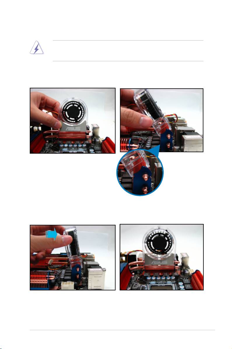
2.7.3 Installing the optional fans
Install the optional fan only if you are using a passive cooler or a water cooler.
Installing the optional fan with an active CPU cooler will interfere with the airow
and destabilize the system.
1. Position the fan above the pipe
2. Fit the fan to the grooved edge of
and heatsink assembly.
the heatsink.
3. Carefully push down the fan until
4. The photo shows the fan installed
it snugly ts the heatsink, then
on the motherboard.
connect the fan cable.
ASUS P5E3 Premium/WiFi-AP @n 2-39
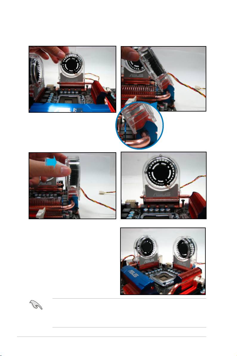
5. Follow the previous instructions to install the other optional fan.
6. The photo on the right shows the
fans installed on the motherboard.
• Plug the optional fan cables to the CHA_FAN1, CHA_FAN2 or PWR_FAN
connector on the motherboard.
•
Make sure the optional fan is installed correctly to prevent damage to the
fan and motherboard components.
2-40 Chapter 2: Hardware information
