Asus P5E3 Premium WiFi-AP@n: BIOS setup
BIOS setup: Asus P5E3 Premium WiFi-AP@n

This chapter tells how to change
the system settings through the BIOS
Setup menus. Detailed descriptions
of the BIOS parameters are also
provided.
BIOS setup
4

Chapter summary
4
4.1 Managing and updating your BIOS ............................................ 4-1
4.2
BIOS setup program .................................................................... 4-8
4.3 Main menu .................................................................................. 4-11
4.4 Ai Tweaker menu ........................................................................
4-16
4.5 Advanced menu .........................................................................
4-24
4.6 Power menu ................................................................................
4-30
4.7 Boot menu ..................................................................................
4-35
4.8 Tools menu .................................................................................
4-39
4.9 Exit menu ....................................................................................
4-43
ASUS P5E3 Premium/WiFi-AP @n

4.1 Managing and updating your BIOS
The following utilities allow you to manage and update the motherboard Basic
Input/Output System (BIOS) setup.
®
1.
ASUS Update (Updates the BIOS in Windows
environment.)
2.
ASUS EZ Flash 2 (Updates the BIOS using a oppy disk or USB ash disk.)
3.
ASUS AFUDOS (Updates the BIOS using a bootable oppy disk)
4.
ASUS CrashFree BIOS 3 (Updates the BIOS using a USB ash disk or the
motherboard support DVD when the BIOS le fails or gets corrupted.)
Refer to the corresponding sections for details on these utilities.
Save a copy of the original motherboard BIOS le to a bootable oppy disk or
USB ash disk in case you need to restore the BIOS in the future. Copy the
original motherboard BIOS using the ASUS Update or AFUDOS utilities.
4.1.1 ASUS Update utility
The ASUS Update is a utility that allows you to manage, save, and update the
®
motherboard BIOS in Windows
environment. The ASUS Update utility allows you
to:
• Save the current BIOS le
• Download the latest BIOS le from the Internet
• Update the BIOS from an updated BIOS le
• Update the BIOS directly from the Internet, and
• View the BIOS version information.
This utility is available in the support DVD that comes with the motherboard
package.
ASUS Update requires an Internet connection either through a network or an
Internet Service Provider (ISP).
Installing ASUS Update
To install ASUS Update:
1. Place the support DVD in the optical drive. The Drivers menu appears.
2. Click the Utilities tab, then click Install ASUS Update VX.XX.XX.
3. The ASUS Update utility is copied to your system.
ASUS P5E3 Premium/WiFi-AP @n 4-1
®
Quit all Windows
applications before you update the BIOS using this utility.
Updating the BIOS through the Internet
To update the BIOS through the Internet:
®
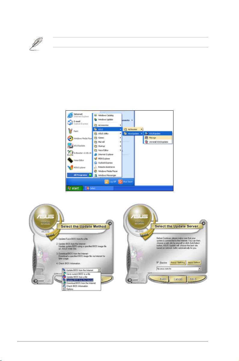
1. Launch the ASUS Update utility from the Windows
desktop by clicking Start
> Programs > ASUS > ASUSUpdate > ASUSUpdate. The ASUS Update
main window appears.
2. Select Update BIOS from the
3. Select the ASUS FTP site nearest
Internet option from the drop-down
you to avoid network trafc, or
menu, then click Next.
click Auto Select. Click Next.
4-2 Chapter 4: BIOS setup
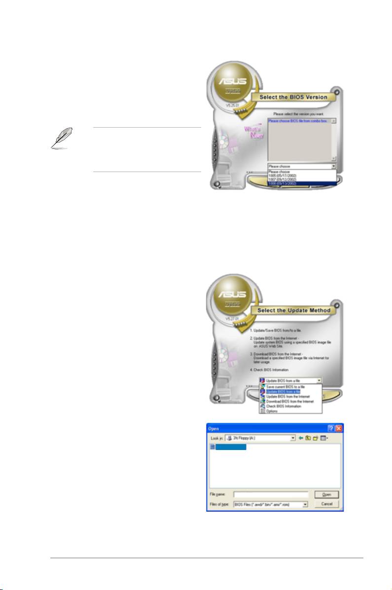
4. From the FTP site, select the BIOS
version that you wish to download.
Click Next.
5. Follow the screen instructions to
complete the update process.
The ASUS Update utility is
capable of updating itself through
the Internet. Always update the
utility to avail all its features.
Updating the BIOS through a BIOS le
To update the BIOS through a BIOS le:
®
1. Launch the ASUS Update utility from the Windows
desktop by clicking Start
> Programs > ASUS > ASUSUpdate > ASUSUpdate. The ASUS Update
main window appears.
2. Select
Update BIOS from a le
option from the drop-down menu,
then click Next.
3. Locate the BIOS le from the Open
window, then click Open.
P5E3P.ROM
4. Follow the screen instructions to
complete the update process.
P5E3P
ASUS P5E3 Premium/WiFi-AP @n 4-3

4.1.2 ASUS EZ Flash 2 utility
The ASUS EZ Flash 2 feature allows you to update the BIOS without having to go
through the long process of booting from a oppy disk and using a DOS-based
utility. The EZ Flash 2 utility is built-in the BIOS chip so it is accessible by pressing
<Alt> + <F2> during the Power-On Self Tests (POST).
To update the BIOS using EZ Flash 2:
1. Visit the ASUS website (www.asus.com) to download the latest BIOS le for
the motherboard.
2. Save the BIOS le to a oppy disk or a USB ash disk, then restart the
system.
3. You can launch the EZ Flash 2 by two methods.
(1)
Insert the oppy disk / USB ash disk that contains the BIOS le to the
oppy disk drive or the USB port.
Press <Alt> + <F2> during POST to display the following.
ASUSTek EZ Flash 2 BIOS ROM Utility V3.06
FLASH TYPE: MXIC 25L1605A
Current ROM
Update ROM
BOARD: P5E3 Premium
BOARD: Unknown
VER: 0110
VER: Unknown
DATE: 11/08/07
DATE: Unknown
PATH: A:\
A:
Note
[Enter] Select or Load [B] Backup [ESC] Exit
[Tab] Switch [Up/Down/Home/End] Move
(2) Enter BIOS setup program. Go to the
Tools menu to select EZ Flash2
and press <Enter> to enable it.
You can switch between drives by pressing <Tab> before the correct le
is found. Then press <Enter>.
4. When the correct BIOS le is found, EZ Flash 2 performs the BIOS update
process and automatically reboots the system when done.
• This function can support devices such as USB ash disk, or oppy disk
with
FAT 32/16
format and single partition only.
• DO NOT shut down or reset the system while updating the BIOS to prevent
system boot failure!
4-4 Chapter 4: BIOS setup

4.1.3 AFUDOS utility
The AFUDOS utility allows you to update the BIOS le in DOS environment using
a bootable oppy disk with the updated BIOS le. This utility also allows you to
copy the current BIOS le that you can use as backup when the BIOS fails or gets
corrupted during the updating process.
Copying the current BIOS
To copy the current BIOS le using the AFUDOS utility:
• Make sure that the oppy disk is not write-protected and has at least
1024KB free space to save the le.
• The succeeding BIOS screens are for reference only. The actual BIOS
screen displays may not be same as shown.
1. Copy the AFUDOS utility (afudos.exe) from the motherboard support DVD to
the bootable oppy disk you created earlier.
2. Boot the system in DOS mode, then at the prompt type:
afudos /o[lename]
where the [lename] is any user-assigned lename not more than eight
alphanumeric characters for the main lename and three alphanumeric
characters for the extension name.
A:\>afudos /oOLDBIOS1.rom
Main lename Extension name
3. Press <Enter>. The utility copies the current BIOS le to the oppy disk.
A:\>afudos /oOLDBIOS1.rom
AMI Firmware Update Utility - Version 1.19(ASUS V2.07(03.11.24BB))
Copyright (C) 2002 American Megatrends, Inc. All rights reserved.
Reading ash ..... done
Write to le...... ok
A:\>
The utility returns to the DOS prompt after copying the current BIOS le.
Updating the BIOS le
To update the BIOS le using the AFUDOS utility:
1. Visit the ASUS website (www.asus.com) and download the latest BIOS le for
the motherboard. Save the BIOS le to a bootable oppy disk.
ASUS P5E3 Premium/WiFi-AP @n 4-5

Write the BIOS lename on a piece of paper. You need to type the exact BIOS
lename at the DOS prompt.
2. Copy the AFUDOS utility (afudos.exe) from the motherboard support DVD to
the bootable oppy disk you created earlier.
3. Boot the system in DOS mode, then at the prompt type:
afudos /i[lename]
where [lename] is the latest or the original BIOS le on the bootable oppy
disk.
A:\>afudos /iP5E3P.ROM
4. The utility veries the le and starts updating the BIOS.
A:\>afudos /iP5E3P.ROM
AMI Firmware Update Utility - Version 1.19(ASUS V2.07(03.11.24BB))
Copyright (C) 2002 American Megatrends, Inc. All rights reserved.
WARNING!! Do not turn off power during ash BIOS
Reading le ....... done
Reading ash ...... done
Advance Check ......
Erasing ash ...... done
Writing ash ...... 0x0008CC00 (9%)
DO NOT shut down or reset the system while updating the BIOS to prevent
system boot failure!
5. The utility returns to the DOS prompt after the BIOS update process is
completed. Reboot the system from the hard disk drive.
A:\>afudos /iP5E3P.ROM
AMI Firmware Update Utility - Version 1.19(ASUS V2.07(03.11.24BB))
Copyright (C) 2002 American Megatrends, Inc. All rights reserved.
WARNING!! Do not turn off power during ash BIOS
Reading le ....... done
Reading ash ...... done
Advance Check ......
Erasing ash ...... done
Writing ash ...... done
Verifying ash .... done
Please restart your computer
A:\>
4-6 Chapter 4: BIOS setup

4.1.4 ASUS CrashFree BIOS 3 utility
The ASUS CrashFree BIOS 3 is an auto recovery tool that allows you to restore
the BIOS le when it fails or gets corrupted during the updating process. You can
update a corrupted BIOS le using the motherboard support DVD or the USB ash
disk that contains the updated BIOS le.
• Prepare the motherboard support DVD, the oppy disk or the USB ash
disk containing the updated motherboard BIOS before using this utility.
• If you use a SATA optical drive, always connect the SATA cable to the
SATA1/SATA 2/SATA3/SATA4 connector; otherwise, the utility will not
function.
Recovering the BIOS from the support DVD
To recover the BIOS from the support DVD:
1. Turn on the system.
2. Insert the motherboard support DVD to the optical drive.
3. The utility displays the following message and automatically checks the DVD
for the BIOS le.
Bad BIOS checksum. Starting BIOS recovery...
Checking for oppy...
When found, the utility reads the BIOS le and starts ashing the corrupted
BIOS le.
Bad BIOS checksum. Starting BIOS recovery...
Checking for oppy...
Floppy found!
Reading le “P5E3P.ROM”. Completed.
Start ashing...
4. Restart the system after the utility completes the updating process.
Recovering the BIOS from the USB ash disk
To recover the BIOS from the USB ash disk:
1. Insert the USB ash disk that contains BIOS le to the USB port.
2. Turn on the system.
3. The utility will automatically checks the devices for the BIOS le When found,
the utility reads the BIOS le and starts ashing the corrupted BIOS le.
4. Restart the system after the utility completes the updating process.
• Only the USB ash disk with FAT 32/16 format and single partition can
support ASUS CrashFree BIOS 3. The device size should be smaller than
8GB.
• DO NOT shut down or reset the system while updating the BIOS! Doing so
can cause system boot failure!
ASUS P5E3 Premium/WiFi-AP @n 4-7

4.2 BIOS setup program
This motherboard supports a programmable Serial Peripheral Interface (SPI) chip
that you can update using the provided utility described in section 4.1 Managing
and updating your BIOS.
Use the BIOS Setup program when you are installing a motherboard, reconguring
your system, or prompted to “Run Setup.” This section explains how to congure
your system using this utility.
Even if you are not prompted to use the Setup program, you can change the
conguration of your computer in the future. For example, you can enable the
security password feature or change the power management settings. This
requires you to recongure your system using the BIOS Setup program so that the
computer can recognize these changes and record them in the CMOS RAM of the
SPI chip.
The SPI chip on the motherboard stores the Setup utility. When you start up the
computer, the system provides you with the opportunity to run this program. Press
<Del> during the Power-On Self-Test (POST) to enter the Setup utility; otherwise,
POST continues with its test routines.
If you wish to enter Setup after POST, restart the system by pressing
<Ctrl+Alt+Delete>, or by pressing the reset button on the system chassis. You can
also restart by turning the system off and then back on. Do this last option only if
the rst two failed.
The Setup program is designed to make it as easy to use as possible. Being a
menu-driven program, it lets you scroll through the various sub-menus and make
your selections from the available options using the navigation keys.
• The default BIOS settings for this motherboard apply for most conditions
to ensure optimum performance. If the system becomes unstable after
changing any BIOS settings, load the default settings to ensure system
compatibility and stability. Select the Load Setup Defaults item under the
Exit Menu. See section 4.9 Exit Menu.
• The BIOS setup screens shown in this section are for reference purposes
only, and may not exactly match what you see on your screen.
• Visit the ASUS website (www.asus.com) to download the latest BIOS le for
this motherboard.
4-8 Chapter 4: BIOS setup
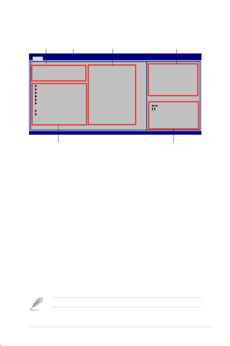
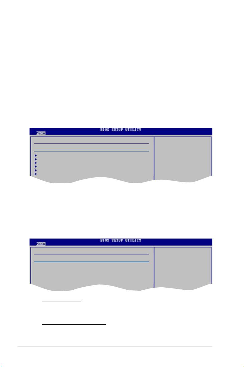
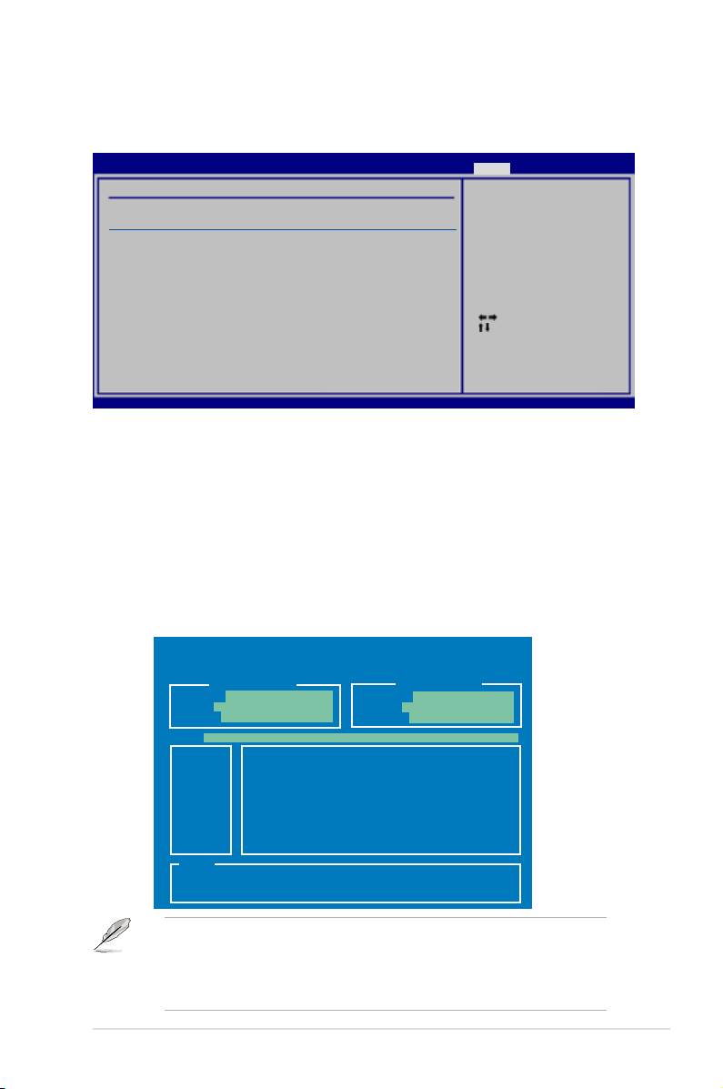
4.2.1 BIOS menu screen
Menu bar
Conguration eldsMenu items
General help
BIOS SETUP UTILITY
Main Ai Tweaker Advanced Power Boot Tools Exit
System Time [10:55:25]
Use [ENTER], [TAB]
System Date [Wed 11/07/2007]
or [SHIFT-TAB] to
Legacy Diskette A [1.44M, 3.5 in.]
select a eld.
Language [English]
Use [+] or [-] to
SATA1 [HDT722516DLA380]
congure the System
SATA2 [ASUS CRW-5232A1]
Time.
SATA3 [Not Detected]
SATA4 [Not Detected]
SATA5 [Not Detected]
SATA6 [Not Detected]
Select Screen
Select Item
SATA Conguration
+-
Change Field
System Information
Tab Select Field
F1 General Help
F10 Save and Exit
ESC Exit
v02.61 (C)Copyright 1985-2007, American Megatrends, Inc.
Sub-menu items
Navigation keys
4.2.2 Menu bar
The menu bar on top of the screen has the following main items:
Main For changing the basic system conguration
Ai Tweaker
For changing the overclocking settings
Advanced For changing the advanced system settings
Power For changing the advanced power management (APM)
conguration
Boot For changing the system boot conguration
Tools For conguring options for special functions
Exit For selecting the exit options and loading default
settings
To select an item on the menu bar, press the right or left arrow key on the keyboard
until the desired item is highlighted.
4.2.3 Navigation keys
At the bottom right corner of a menu screen are the navigation keys for that
particular menu. Use the navigation keys to select items in the menu and change
the settings.
The navigation keys may differ from one screen to another.
ASUS P5E3 Premium/WiFi-AP @n 4-9

4.2.4 Menu items
Use [ENTER], [TAB],
System Time [06:22:54]
The highlighted item on the menu bar
or [SHIFT-TAB] to
System Date [Mon 04/23/2007]
Floppy Diskette A [1.44M, 3.5 in.]
select a eld.
Language [English]
displays the specic items for that
Use [+] or [-] to
SATA1 [Not Detected]
congure system.
SATA2 [Not Detected]
menu. For example, selecting Main
SATA3 [Not Detected]
SATA4 [Not Detected]
SATA5 [Not Detected]
shows the Main menu items.
SATA6 [Not Detected]
SATA Conguration
System Information
The other items (Advanced, Power,
Boot, and Exit) on the menu bar have
their respective menu items.
Main menu items
4.2.5 Sub-menu items
A solid triangle before each item on any menu screen means that the iteam has a
sub-menu. To display the sub-menu, select the item and press <Enter>.
4.2.6 Conguration elds
These elds show the values for the menu items. If an item is user- congurable,
you can change the value of the eld opposite the item. You cannot select an item
that is not user-congurable.
A congurable eld is enclosed in brackets, and is highlighted when selected. To
change the value of a eld, select it then press <Enter> to display a list of options.
Refer to 4.2.7 Pop-up window.
4.2.7 Pop-up window
Select a menu item then press <Enter> to display a pop-up window with the
conguration options for that item.
4.2.8 Scroll bar
A scroll bar appears on the right side of a
menu screen when there are items that do not
t on the screen. Press the
Up/Down arrow keys or <Page Up> /<Page
Down> keys to display the other items on the
screen.
4.2.9 General help
Pop-up window
At the top right corner of the menu screen is a
Scroll bar
brief description of the selected item.
4-10 Chapter 4: BIOS setup
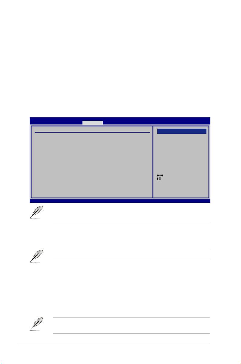
4.3 Main menu
When you enter the BIOS Setup program, the Main menu screen appears, giving
you an overview of the basic system information.
Refer to section 4.2.1 BIOS menu screen for information on the menu screen
items and how to navigate through them.
BIOS SETUP UTILITY
Main Ai Tweaker Advanced Power Boot Tools Exit
System Time [10:55:25]
Use [ENTER], [TAB]
System Date [Wed 11/07/2007]
or [SHIFT-TAB] to
Legacy Diskette A [1.44M, 3.5 in.]
select a eld.
Language [English]
Use [+] or [-] to
SATA1 [HDT722516DLA380]
congure the System
SATA2 [ASUS CRW-5232A1]
Time.
SATA3 [Not Detected]
SATA4 [Not Detected]
SATA5 [Not Detected]
SATA6 [Not Detected]
Select Screen
Select Item
SATA Conguration
+-
Change Field
System Information
Tab Select Field
F1 General Help
F10 Save and Exit
ESC Exit
v02.61 (C)Copyright 1985-2007, American Megatrends, Inc.
4.3.1 System Time [xx:xx:xx]
Allows you to set the system time.
4.3.2 System Date [Day xx/xx/xxxx]
Allows you to set the system date.
4.3.3 Legacy Diskette A [1.44M, 3.5 in.]
Sets the type of oppy drive installed.
Conguration options: [Disabled] [720K , 3.5 in.] [1.44M, 3.5 in.]
4.3.4 Language [English]
Allows you to select the display language for the BIOS setup screen.
Conguration options: [Chinese(BIG5)] [Chinese(GB)] [Japanese] [Français]
[German] [English]
ASUS P5E3 Premium/WiFi-AP @n 4-11

4.3.5 SATA 1-6
While entering Setup, the BIOS automatically detects the presence of Serial ATA
devices. There is a separate sub-menu for each SATA device. Select a device item
then press <Enter> to display the SATA device information.
BIOS SETUP UTILITY
Main
SATA 1
Select the type of
device connected to
Device :Hard Disk
the system.
Vendor :HDT722516DLA380
Size :164.7GB
LBA Mode :Supported
Block Mode:16Sectors
PIO Mode :4
Async DMA :MultiWord DMA-2
Ultra DMA :Ultra DMA-5
SMART Monitoring: Supported
Type [Auto]
LBA/Large Mode [Auto]
Select Screen
Block(Multi-Sector Transfer) [Auto]
Select Item
PIO Mode [Auto]
+-
Change Option
DMA Mode [Auto]
F1 General Help
SMART Monitoring [Auto]
F10 Save and Exit
32Bit Data Transfer [Enabled]
ESC Exit
v02.61 (C)Copyright 1985-2007, American Megatrends, Inc.
The BIOS automatically detects the values opposite the dimmed items (Device,
Vendor, Size, LBA Mode, Block Mode, PIO Mode, Async DMA, Ultra DMA, and
SMART monitoring). These values are not user-congurable. These items show
N/A if no IDE device is installed in the system.
Type [Auto]
Selects the type of IDE drive. Setting to [Auto] allows automatic selection of the
appropriate IDE device type. Select [CDROM] if you are specically conguring a
CD-ROM drive. Select [ARMD] (ATAPI Removable Media Device) if your device is
either a ZIP, LS-120, or MO drive.
Conguration options: [Not Installed] [Auto] [CDROM] [ARMD]
LBA/Large Mode [Auto]
Enables or disables the LBA mode. Setting to [Auto] enables the LBA mode if the
device supports this mode, and if the device was not previously formatted with LBA
mode disabled.
Conguration options: [Disabled] [Auto]
Block (Multi-Sector Transfer) [Auto]
Enables or disables data multi-sectors transfers. When set to [Auto], the data
transfer from and to the device occurs multiple sectors at a time if the device
supports multi-sector transfer feature. When set to [Disabled], the data transfer
from and to the device occurs one sector at a time.
Conguration options: [Disabled] [Auto]
PIO Mode [Auto]
Allows you to select the data transfer mode.
Conguration options: [Auto] [0] [1] [2] [3] [4]
4-12 Chapter 4: BIOS setup

DMA Mode [Auto]
Selects the DMA mode.
Conguration options: [Auto] [SWDMA0] [SWDMA1] [SWDMA2] [MWDMA0]
[MWDMA1] [MWDMA2] [UDMA0] [UDMA1] [UDMA2] [UDMA3] [UDMA4] [UDMA5]
SMART Monitoring [Auto]
Sets the Smart Monitoring, Analysis, and Reporting Technology.
Conguration options: [Auto] [Disabled] [Enabled]
32Bit Data Transfer [Enabled]
Enables or disables 32-bit data transfer.
Conguration options: [Disabled] [Enabled]
4.3.6 SATA Conguration
The items in this menu allow you to set or change the congurations for the SATA
devices installed in the system. Select an item then press <Enter> if you want to
congure the item.
SATA Conguration
Options
SATA Conguraton [Enhanced]
Disabled
Congure SATA as [IDE]
Compatible
Enhanced
Hard Disk Write Protect [Disabled]
SATA Detect Time Out (Sec) [35]
SATA Conguration [Enhanced]
Conguration options: [Disabled] [Compatible] [Enhanced]
Configure SATA as [IDE]
This sub-item appears only when you set the SATA Conguration item to
[Compatible] or [Enhanced] and allows you to set the SATA conguration.
Conguration options: [IDE] [RAID] [AHCI]
• If you want to use the Serial ATA hard disk drives as Parallel ATA physical
storage devices, keep the default setting [IDE].
• If you want the Serial ATA hard disk drives to use the Advanced Host
Controller Interface (AHCI), set this item to [AHCI]. The AHCI allows
the onboard storage driver to enable advanced Serial ATA features that
increases storage performance on random workloads by allowing the drive
to internally optimize the order of commands.
• If you want to create a RAID 0, RAID 1, RAID 5, RAID 10, or the Intel®
Matrix Storage Technology conguration from the Serial ATA hard disk
drives, set this item to [RAID].
ASUS P5E3 Premium/WiFi-AP @n 4-13
Hard Disk Write Protect [Disabled]
Disables or enables device write protection. This will be effective only if the device
is accessed through BIOS.
Conguration option: [Disabled] [Enabled]
SATA Detect Time Out (Sec) [35]
Selects the time out value for detecting ATA/ATAPI devices.
Conguration options: [0] [5] [10] [15] [20] [25] [30] [35]
4.3.7 AHCI Conguration
This menu is the section for AHCI conguration. It appears only when you set the
item Congure SATA as from the sub-menu of SATA Conguration to [AHCI].
AHCI Settings
Some SATA CD/DVD in
AHCI CD/DVD Boot Time out [15]
AHCI mode need to
wait ready longer.
AHCI Port1 [Not Detected]
AHCI Port2 [Not Detected]
AHCI Port3 [Not Detected]
AHCI Port4 [Not Detected]
AHCI Port5 [Not Detected]
AHCI Port6 [Not Detected]
AHCI CD/DVD Boot Time out [15]
Selects the boot time out value for SATA CD/DVD devices in AHCI mode.
Congifuration options: [0] [5] [10] [15] [20] [25] [30] [35]
AHCI Port1~6 [XXXX]
Displays the status of auto-detection of SATA devices.
AHCI Port1
Select the type of
Device :Not Detected
devices connected to
the system.
SATA Port1 [Auto]
SMART Monitoring [Enabled]
SATA Port1 [Auto]
Allows you to select the type of device connected to the system.
Conguration options: [Auto] [Not Installed]
SMART Monitoring [Enabled]
Allows you to set the Self-Monitoring, Analysis and Reporting Technology.
Congration options: [Disabled] [Enabled]
4-14 Chapter 4: BIOS setup

4.3.8 System Information
This menu gives you an overview of the general system specications. The BIOS
automatically detects the items in this menu.
BIOS SETUP UTILITY
Main
ASUS BIOS
Version : 0110
Build Date : 11/08/07
Processor
Type : Intel(R) Core(TM)2 Duo CPU @ 3.00GHz
Speed : 3000 MHz
Count : 2
System Memory
Available : 512 MB
Select Screen
Select Item
F1 General Help
F10 Save and Exit
ESC Exit
v02.61 (C)Copyright 1985-2007, American Megatrends, Inc.
ASUS BIOS
Displays the auto-detected BIOS information.
Processor
Displays the auto-detected CPU specication.
System Memory
Displays the auto-detected system memory.
ASUS P5E3 Premium/WiFi-AP @n 4-15
4.4 Ai Tweaker menu
The Ai Tweaker menu items allow you to congure overclocking-related items.
Take caution when changing the settings of the Ai Tweaker menu items.
Incorrect eld values can cause the system to malfunction.
BIOS SETUP UTILITY
Main Ai Tweaker Advanced Power Boot Tools Exit
Congure System Performance Settings
[X.M.P.]
When X.M.P. is enabled
Ai Overclock Tuner [Auto]
the CPU FSB frequency,
CPU Ratio Control [Auto]
CPU ratio and memory
FSB Strap to North Bridge [Auto]
parameters will be
DRAM Frequency [Auto]
optimized automatically
DRAM Command Rate [Auto]
DRAM CMD Skew on Channel A [Auto]
DRAM CMD Skew on Channel B [Auto]
DRAM CLK Skew on Channel A [Auto]
DRAM CLK Skew on Channel B [Auto]
DRAM Timing Control [Auto]
1st Information : 6-6-6-15-4-36-6-4
Select Screen
2nd Information : 8-4-6-4-7-4-7
Select Item
3rd Information : 15-6-1-7-7
+- Change Option
DRAM Static Read Control [Auto]
F1 General Help
DRAM Dynamic Write Control [Auto]
F10 Save and Exit
ESC Exit
Ai Clock Twister [Auto]
Ai Transaction Booster [Auto]
v02.61 (C)Copyright 1985-2007, American Megatrends, Inc.
Scroll down to display the following items:
C/P : A1 A2 A3 A4 A5 |
LVL : 11 11 11 11 11
**** Please key in voltage numbers directly! ****
CPU Voltage [Auto]
CPU PLL Voltage [Auto]
FSB Termination Voltage [Auto]
DRAM Voltage [Auto]
NB Voltage [Auto]
SB voltage [Auto]
Select Screen
Clock Over-Charging Voltage [Auto]
Select Item
*************************************************
+- Change Option
Load-Line Calibration [Auto]
F1 General Help
CPU GTL Voltage Reference [Auto]
F10 Save and Exit
NB GTL Voltage Reference [Auto]
ESC Exit
CPU Spread Spectrum [Auto]
PCIE Spread Spectrum [Auto]
v02.61 (C)Copyright 1985-2007, American Megatrends, Inc.
4.4.1 Ai Overclock Tuner [Auto]
Allows selection of CPU overclocking options to achieve desired CPU internal
frequency. Select either one of the preset overclocking conguration options:
Manual
Allows you to individually set overclocking parameters.
Auto
Loads the optimal settings for the system.
X.M.P.
If you install memory module(s) supporting the eXtreme
Memory Prole (X.M.P.) Technology, choose this item to set the
prole(s) supported by your memory module(s) for optimizing
the system performance.
4-16 Chapter 4: BIOS setup

The conguration options for the following sub-item vary depending on the
DIMMs you install on the motherboard.
eXtreme Memory Profile [Disabled]
This item appears only when you set the Ai Overclock Tuner item to
[X.M.P.]. Allows you to select the X.M.P. mode supported by your Memory
module.
Conguration options: [Disabled] [Prole #1] [Prole #2]
To obtain the best performance of the X.M.P. 1800/1600 DIMM, install only
one DIMM on each memory channel. Refer to the table below for X.M.P. DIMM
installation recommendation.
X.M.P. DIMM Installation Recommendation
X.M.P. DIMM Frequency 1800 MHz 1800 MHz 1600 MHz 1600 MHz
DIMM_A1 - √ - √
DIMM_B1 - √ - √
Sockets
DIMM_A2 √ - √ -
DIMM_B2 √ - √ -
4.4.2 CPU Ratio Control [Auto]
Conguration options: [Auto] [Manual].
CPU Ratio Setting [9]
This sub-item appears only when you set the CPU Ratio Control item to
[Manual]. Allows you to set the ratio between CPU Core Clock and FSB
Frequency. Use the <+> and <-> keys to adjust the ratio. If an invalid ratio is
set in CMOS, then actual and setpoint values may differ.
4.4.3 FSB Strap to North Bridge [Auto]
When set to [Auto], the FSB Strap will be adjusted automatically by FSB
Frequency and DRAM Frequency.
Congifuration options: [Auto] [200MHz] [266MHz] [333MHz] [400MHz]
The following two items (FSB Frequency and PCIE Freuency) on the next
page appear only when you set the Ai Overclock Tuner item to [Manual].
ASUS P5E3 Premium/WiFi-AP @n 4-17

FSB Frequency [XXX]
Displays the frequency sent by the clock generator to the system bus and PCI bus.
The value of this item is auto-detected by the BIOS. Use the <+> and <-> keys to
adjust the FSB frequency. You can also type the desired CPU frequency using the
numeric keypad. The values range from 200 to 800. Refer to the table below for
the correct Front Side Bus and CPU External Frequency settings.
FSB/CPU External Frequency Synchronization
Front Side Bus
FSB 1600 FSB 1333 FSB 1066 FSB 800
CPU External Frequency
400 MHz 333 MHz 266 MHz 200 MHz
PCIE Frequency [Auto]
Allows you to set the PCI Express frequency. Use the <+> and <-> keys to adjust
the PCIE frequency. The values range from 100 to 180.
4.4.4 DRAM Frequency [Auto]
Allows you to set the DDR3 operating frequency.
Conguration options: [Auto] [DDR3-667MHz] [DDR3-800MHz] [DDR3-835MHz]
[DDR3-887MHz] [DDR3-1002MHz] [DDR3-1066MHz] [DDR3-1111MHz] [DDR3-
1333MHz] [DDR3-*1600MHz*] [DDR3-*1800MHz*] [DDR3-*2000MHz*]
• The DRAM Frequency conguration options vary with the FSB Frequency
settings.
• When the
DRAM Frequency item is set to [DDR3-*1600MHz*], [DDR3-
*1800MHz*] or [DDR3-*2000MHz*], the FSB Frequency and CPU Ratio
Setting items will be optimized automatically.
• Selecting a very high DRAM frequency may cause the system to become
unstable! If this happens, revert to the default setting.
• DDR3-667 help: DRAM frequency lower than 800 MHz may cause system
boot failure due to spec violation.
4.4.5 DRAM Command Rate [Auto]
Set this item to [1N] to provide possibility to accelerate DRAM performance or [2N]
to enhance DRAM overclocking ability.
Conguration options: [Auto] [1N] [2N]
4-18 Chapter 4: BIOS setup

4.4.6 DRAM CMD Skew on Channel A/B [Auto]
These items are adjustable only when you set the DRAM Command Rate item to
[1N] and may help enhancing DRAM stability on 1N mode.
Conguration options: [Auto] [Advance 175ps] [Advance 150ps] [Advance 125ps]
[Advance 100ps] [Advance 75ps] [Advance 50ps] [Advance 25ps] [Normal] [Delay
25ps] [Delay 50ps] [Delay 75ps] [Delay 100ps] [Delay 125ps] [Delay 150ps] [Delay
175ps]
4.4.7 DRAM CLK Skew on Channel A/B [Auto]
Adjusting these items may help enhancing DRAM overclocking ability.
Conguration options: [Auto] [Advance 350ps] [Advance 300ps] [Advance 250ps]
[Advance 200ps] [Advance 150ps] [Advance 100ps] [Advance 50ps] [Normal]
[Delay 50ps] [Delay 100ps] [Delay 150ps] [Delay 200ps] [Delay 250ps] [Delay
300ps] [Delay 350ps]
4.4.8 DRAM Timing Control [Auto]
Conguration options: [Auto] [Manual]
• The following sub-items apprear only when you set the DRAM Timing
Control item to [Manual].
• The conguration options for some of the following items vary depending
on the DIMMs you install on the motherboard.
1st Information: 6-6-6-15-4-36-6-4
The values vary depending on your settings of the following sub-items:
CAS# Latency [ 5 DRAM Clocks]
Conguration options: [ 4 DRAM Clocks] [ 5 DRAM Clocks] [ 6 DRAM Clocks]
[ 7 DRAM Clocks] [ 8 DRAM Clocks] [ 9 DRAM Clocks] [10 DRAM Clocks] [11
DRAM Clocks]
RAS# to CAS# Delay [ 5 DRAM Clocks]
Conguration options: [ 3 DRAM Clocks] [ 4 DRAM Clocks]~[17 DRAM
Clocks] [18 DRAM Clocks]
RAS# PRE Time [ 5 DRAM Clocks]
Conguration options: [ 3 DRAM Clocks] [ 4 DRAM Clocks]~[17 DRAM
Clocks] [18 DRAM Clocks]
RAS# ACT Time [15 DRAM Clocks]
Conguration options: [ 3 DRAM Clocks] [ 4 DRAM Clocks]~[33 DRAM
Clocks] [34 DRAM Clocks]
RAS# to RAS# Delay [Auto]
Conguration options: [Auto] [ 1 DRAM Clocks]~[15 DRAM Clocks]
ASUS P5E3 Premium/WiFi-AP @n 4-19

REF Cycle Time [Auto]
Conguration options: [Auto] [30 DRAM Clocks] [36 DRAM Clocks]
[48 DRAM Clocks] [60 DRAM Clocks] [72 DRAM Clocks]
WRITE Recovery Time [Auto]
Conguration options: [Auto] [ 1 DRAM Clocks]~[15 DRAM Clocks]
READ to PRE Time[Auto]
Conguration options: [Auto] [ 1 DRAM Clocks]~[15 DRAM Clocks]
2nd Information: 8-4-6-4-7-4-7
The values vary depending on your settings of the following sub-items:
READ to WRITE Delay(S/D) [Auto]
Conguration options: [Auto] [ 1 DRAM Clocks]~[15 DRAM Clocks]
WRITE to READ Delay(S) [Auto]
Conguration options: [Auto] [ 1 DRAM Clocks]~[15 DRAM Clocks]
WRITE to READ Delay(D) [Auto]
Conguration options: [Auto] [ 1 DRAM Clocks]~[15 DRAM Clocks]
READ To READ Delay(S) [Auto]
Conguration options: [Auto] [ 1 DRAM Clocks]~[15 DRAM Clocks]
READ To READ Delay(D) [Auto]
Conguration options: [Auto] [ 1 DRAM Clocks]~[15 DRAM Clocks]
WRITE To WRITE Delay(S) [Auto]
Conguration options: [Auto] [ 1 DRAM Clocks]~[15 DRAM Clocks]
WRITE To WRITE Delay(D) [Auto]
Conguration options: [Auto] [ 1 DRAM Clocks]~[15 DRAM Clocks]
3rd Information: 15-6-1-7-7
The values vary depending on your settings of the following sub-items:
WRITE to PRE Delay [Auto]
Conguration options: [Auto] [ 1 DRAM Clocks]~[31 DRAM Clocks]
READ to PRE Delay [Auto]
Conguration options: [Auto] [ 1 DRAM Clocks]~[15 DRAM Clocks]
PRE to PRE Delay [Auto]
Conguration options: [Auto] [ 1 DRAM Clocks]~[ 3 DRAM Clocks]
ALL PRE to ACT Delay [Auto]
Conguration options: [Auto] [ 1 DRAM Clocks]~[15 DRAM Clocks]
ALL PRE to REF Delay [Auto]
Conguration options: [Auto] [ 1 DRAM Clocks]~[15 DRAM Clocks]
4-20 Chapter 4: BIOS setup

4.4.9 DRAM Static Read Control [Auto]
Conguration options: [Auto] [Disabled] [Enabled]
4.4.10 DRAM Dynamic Write Control [Auto]
Conguration options: [Auto] [Disabled] [Enabled]
4.4.11 Ai Clock Twister [Auto]
Allows you to set the DRAM performance. Set this item to [Light] to enhance
DRAM compatibility, or [Strong] to enhance DRAM performance.
Conguration options: [Auto] [Moderate] [Light] [Strong]
4.4.12 Ai Transaction Booster [Auto]
Allows you to set the system performance.
Conguration options: [Auto] [Manual]
The following two sub-items appear only when you set the Ai Transaction
Booster item to [Manual].
Common Performance Level [05]
Set this item to a higher level for better compatibility or a lower level for better
performance. Use the <+> and <-> keys to adjust the value. The values
range from 1 to 31.
Pull-In of CHA/B PH1/2/3/4/5 [Disabled]
Set this item to [Enabled] to apply enhancement on DRAM Channel A and B,
Phase 1 to 5. The number of phases is determined by DRAM frequency and
FSB strap.
Conguration options: [Disabled] [Enabled]
The following seven items are adjusted by typing the desired values using the
numeric keypad and press the <Enter> key. You can also use the <+> and <->
keys to adjust the value. To restore the default setting, type [auto] using the
keyboard and press the <Enter> key.
4.4.13 CPU Voltage [Auto]
Allows you to set the CPU VCore voltage. The values range from 0.85000V to
2.10000V* with a 0.00625V interval.
• Refer to the CPU documentation before setting the CPU Vcore voltage.
Setting a high VCore voltage may damage the CPU permanently, and
setting a low VCore voltage may make the system unstable.
• The value [2.10000V] of the
CPU Voltage item is supported only if the
OV_CPU jumper is enalbed, otherwise the maximum voltage suppoted is
[1.70000V]. See 2. CPU / Northbridge overvoltage setting on page 2-23
for details.
ASUS P5E3 Premium/WiFi-AP @n 4-21

4.4.14 CPU PLL Voltage [Auto]
Allows you to set the CPU PLL voltage. The values range from 1.50V to 2.78V with
a 0.02V interval.
4.4.15 FSB Termination Voltage [Auto]
Allows you to set the front side bus termination voltage. The values range from
1.20V to 1.50V with a 0.02V interval.
4.4.16 DRAM Voltage [Auto]
Allows you to set the DRAM voltage. The values range from 1.50V to 2.78V with a
0.02V interval.
4.4.17 NB Voltage [Auto]
Allows you to set the North Bridge voltage. The values range from 1.25V to 2.21V*
with a 0.02V interval.
• The value [2.21V] of the NB Voltage item is supported only if the OV_NB
jumper is enalbed, otherwise the maximum voltage suppoted is [1.91V].
See 2. CPU / Northbridge overvoltage setting on page 2-23 for details.
• Setting the
CPU PLL Voltage, FSB Termination Voltage, DRAM Voltage
and NB Voltage items to a high level may damage the chipset, memory
module and CPU permanently. Proceed with caution.
• Some values of the
CPU PLL Voltage, FSB Termination Voltage, DRAM
Voltage and NB Voltage items are labeled in different color, indicating the
risk levels of high voltage settings. Refer to the table below for details.
• The system may need better cooling system to work stably under high
voltage settings.
Blue Yellow Purple Red
CPU PLL Voltage 1.50V~1.78V 1.80V~2.00V 2.02V~2.20V 2.22V~2.78V
FSB Termination Voltage 1.20V~1.38V 1.40V~1.50V N/A N/A
DRAM Voltage 1.50V~1.68V 1.70V~1.90V 1.92V~2.10V 2.12V~2.78V
NB Voltage
1.25V~1.41V 1.43V~1.55V 1.57V~1.73V
1.75V~2.21V*
4.4.18 SB Voltage [Auto]
Allows you to set the South Bridge voltage. The values range from 1.05V to 1.20V
with a 0.15V interval.
4.4.19 Clock Over-Charging Voltage [Auto]
Allows you to set the Clock Over-Charging voltage. The values range from 0.70V
to 1.00V with a 0.10V interval.
4-22 Chapter 4: BIOS setup

4.4.20 Load-Line Calibration [Auto]
Allows you to select the CPU Load-Line mode. Set to [Normal] to follow Intel
specications, [Optimized] to adjust CPU Load-Line dynamically, or [Performance]
to improve CPU VDroop directly.
Conguration options: [Auto] [Normal] [Optimized] [Performance]
4.4.21 CPU GTL Voltage Reference [Auto]
Allows you to set the CPU GTL voltage reference. Different ratio might enhance
CPU overclocking ability.
Conguration options: [Auto] [0.67x] [0.65x] [0.63x] [0.62x]
4.4.22 NB GTL Voltage Reference [Auto]
Allows you to set the Northbridge GTL voltage reference. Different ratio might
enhance CPU overclocking ability.
Conguration options: [Auto] [0.67x] [0.61x]
4.4.23 CPU Spread Spectrum [Auto]
Set to [Disabled] to enhance FSB overclocking ability or [Auto] for EMI control.
Conguration options: [Auto] [Disabled]
4.4.24 PCIE Spread Spectrum [Auto]
Set to [Disabled] to enhance PCIE overclocking ability or [Auto] for EMI control.
Conguration options: [Auto] [Disabled]
ASUS P5E3 Premium/WiFi-AP @n 4-23
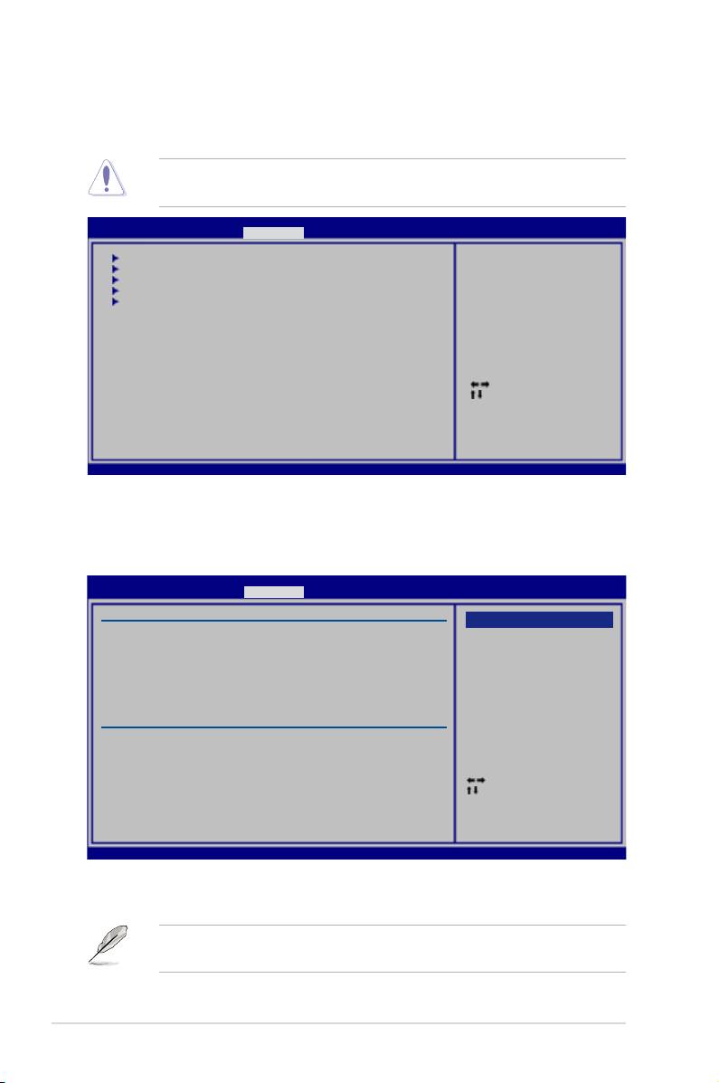
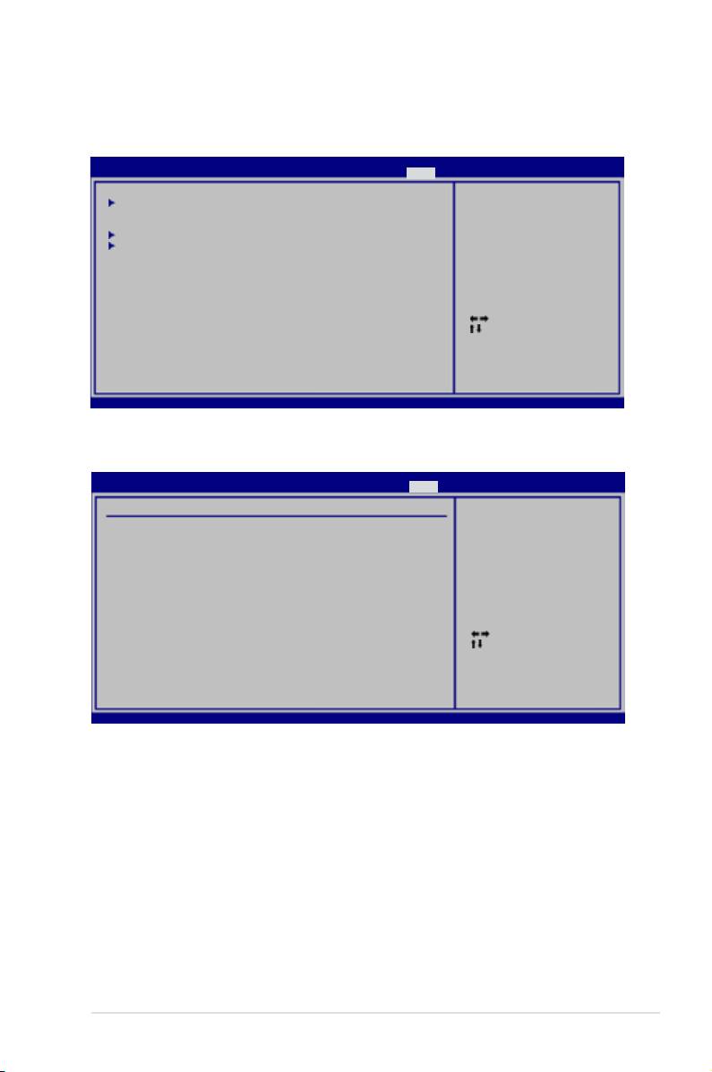
4.5 Advanced menu
The Advanced menu items allow you to change the settings for the CPU and other
system devices.
Take caution when changing the settings of the Advanced menu items. Incorrect
eld values can cause the system to malfunction.
BIOS SETUP UTILITY
Main Ai Tweaker Advanced Power Boot Tools Exit
CPU Conguration
Congure CPU.
Chipset
Onboard Devices Conguration
USB Conguration
PCIPnP
Select Screen
Select Item
Enter Go to Sub Screen
F1 General Help
F10 Save and Exit
ESC Exit
v02.61 (C)Copyright 1985-2007, American Megatrends, Inc.
4.5.1 CPU Conguration
The items in this menu show the CPU-related information that the BIOS
automatically detects.
BIOS SETUP UTILITY
Advanced
Congure advanced CPU settings
Options
Manufacturer:Intel
Brand String:Intel(R) Core(TM)2 Duo CPU @ 3.00GHz
Auto
Frequency :3.00GHz
Manual
FSB Speed :1333 MHz
Cache L1 :64 KB
Cache L2 :4096 KB
CPUID :6F9
Ratio Status:Unlocked (Max:09, Min:06)
Ratio Actual Value :9
CPU Ratio Control [Auto]
C1E Support [Enabled]
CPU TM Function [Enabled]
Vanderpool Technology [Enabled]
Select Screen
Execute Disable Bit [Enabled]
Select Item
Max CPUID Value Limit [Disabled]
Change Option
Intel(R) SpeedStep(TM) Tech. [Enabled]
+-
F1 General Help
F10 Save and Exit
ESC Exit
v02.61 (C)Copyright 1985-2007, American Megatrends, Inc.
CPU Ratio Control [Auto]
Conguration options: [Auto] [Manual]
The following item appears when the item CPU Ratio Control is set to
[Manual].
4-24 Chapter 4: BIOS setup

Ratio CMOS Setting: [9]
Allows you to set the ratio between the CPU Core Clock and the FSB
Frequency. Use <+> and <-> to adjust the value.
Conguration options: [ 6] [ 7] [ 8] [ 9]
C1E Support [Enabled]
Allows you to enable or disable the Enhanced Halt State.
Conguration options: [Disabled] [Enabled]
CPU TM function [Enabled]
This function enables the overheated CPU to throttle the clock speed to cool down.
Conguration options: [Disabled] [Enabled]
Vanderpool Technology [Enabled]
The Vanderpool Technology allows a hardware platform to run multiple operating
systems separately and simultaneously, enabling one system to virtually function
as several systems.
Conguration options: [Disabled] [Enabled]
Execute Disable Bit [Enabled]
Allows you to enable or disable the No-Execution Page Protection Technology.
Setting this item to [Disabled] forces the XD feature ag to always return to zero
(0).
Conguration options: [Disabled] [Enabled]
Max CPUID Value Limit [Disabled]
Setting this item to [Enabled] allows legacy operating systems to boot even without
support for CPUs with extended CPUID functions.
Conguration options: [Disabled] [Enabled]
The following item appears only when you set the CPU Ratio Control item to
[Auto].
Intel(R) SpeedStep (TM) Tech. [Enabled]
When set to [Disabled], the CPU runs at its default speed. When set to [Enabled],
the CPU speed is controlled by the operating system.
Conguration options: [Disabled] [Enabled]
ASUS P5E3 Premium/WiFi-AP @n 4-25
4.5.2 Chipset
The Chipset menu allows you to change the advanced chipset settings. Select an
item then press <Enter> to display the sub-menu.
BIOS SETUP UTILITY
Advanced
Advanced Chipset Settings
Congure North Bridge
features.
WARMING: Setting wrong values in below sections
may cause system to malfunction.
North Bridge Conguration
North Bridge Chipset Conguration
BIOS SETUP UTILITY
Advanced
North Bridge Chipset Conguration
Enabled: Allow
remapping of
Memory Remap Feature [Enabled]
overlapped PCI memory
above the total
Initiate Graphic Adapter [PEG/PCI]
physical memory.
PEG Port Control [Auto]
PEG Port Force x1 [Disabled]
DISABLE: Do not allow
remapping of memory.
Memory Remap Feature [Enabled]
Allows you to enable or disable the remapping of the overlapped PCI memory
above the total physical memory. Enable this option only when you install
64-bit operating system.
Conguration options: [Disabled] [Enabled]
Initiate Graphic Adapter [PEG/PCI]
Allows you to decide which graphics controller to use as the primary boot
device.
Conguration options: [PCI/PEG] [PEG/PCI]
PEG Port Control [Auto]
Conguration options: [Auto] [Disabled]
The following item appears only when you set PEG Port Control to [Auto]
PEG Port Force x1 [Disabled]
Conguration options: [Enabled] [Disabled]
4-26 Chapter 4: BIOS setup

4.5.3 Onboard Device Conguration
BIOS SETUP UTILITY
Advanced
Onboard Device Conguration
Enable or Disable
High Denition
High Denition Audio [Enabled]
Audio Controller
Front Panel Type [HD Audio]
J-Micron eSATA/PATA Controller [Enabled]
Controller Mode [IDE]
Realtek GigaBit LAN [Enabled]
LAN Boot ROM [Disabled]
Marvell GigaBit LAN [Enabled]
LAN Boot ROM [Disabled]
Onboard Wireless LAN [Enabled]
Agere Firewire 1394 [Enabled]
Select Screen
Serial Port1 Address [3F8/IRQ4]
Select Item
+- Change Option
F1 General Help
F10 Save and Exit
ESC Exit
v02.61 (C)Copyright 1985-2007, American Megatrends, Inc.
High Denition Audio [Enabled]
Allows you to enable or disable the High Denition Audio Controller.
Conguration options: [Enabled] [Disabled]
Front Panel Type [HD Audio]
Allows you to set the front panel audio connector (AAFP) mode to legacy
AC’97 or high-denition audio depending on the audio standard that the front
panel audio module supports.
Conguration options: [AC97] [HD Audio]
J-Micron eSATA/PATA Controller [Enabled]
Conguration options: [Enabled] [Disabled]
Controller Mode [IDE]
Conguration options: [RAID] [IDE] [AHCI]
Realtek GigaBit LAN [Enabled]
Conguration options: [Enabled] [Disabled]
LAN Boot ROM [Disabled]
Conguration options: [Disabled] [Enabled]
MarvelI GigaBit LAN [Enabled]
Conguration options: [Enabled] [Disabled]
LAN Boot ROM [Disabled]
Conguration options: [Disabled] [Enabled]
Onboard Wireless LAN [Enabled]
Allows you to enable or disable the onboard USB Wireless LAN.
Conguration options: [Enabled] [Disabled]
ASUS P5E3 Premium/WiFi-AP @n 4-27
Agere Firewire 1394 [Enabled]
Conguration options: [Enabled] [Disabled]
Serial Port1 Address [3F8/IRQ4]
Allows you to select the Serial Port1 base address.
Conguration options: [Disabled] [3F8/IRQ4] [2F8/IRQ3] [3E8/IRQ4] [2E8/IRQ3]
4.5.4 USB Conguration
The items in this menu allows you to change the USB-related features. Select an
item then press <Enter> to display the conguration options.
BIOS SETUP UTILITY
Advanced
USB Conguration
Options
USB Devices Enabled:
1 Mouse
Disabled
Enabled
USB Functions [Enabled]
USB 2.0 Controller [Enabled]
USB 2.0 Controller Mode [HiSpeed]
BIOS EHCI Hand-off [Enabled]
Port 64/60 Emulation [Disabled]
Legacy USB Support [Auto]
Select Screen
Select Item
+-
Change Option
F1 General Help
F10 Save and Exit
ESC Exit
v02.61 (C)Copyright 1985-2007, American Megatrends, Inc.
The USB Devices Enabled item shows the auto-detected values. If no USB
device is detected, the item shows None.
USB Functions [Enabled]
Allows you to enable or disable the USB Host Controllers.
Conguration options: [Disabled] [Enabled]
The following items appear only when you set USB Functions to [Enabled].
USB 2.0 Controller [Enabled]
Allows you to enable or disable the USB 2.0 controller.
Conguration options: [Enabled] [Disabled]
USB 2.0 Controller Mode [HiSpeed]
Allows you to set the USB 2.0 controller mode to HiSpeed (480 Mbps) or
FullSpeed (12 Mbps). Conguration options: [FullSpeed] [HiSpeed]
The USB 2.0 Controller Mode item appears only when you enable the USB
2.0 Controller.
4-28 Chapter 4: BIOS setup

BIOS EHCI Hand-off [Enabled]
Allows you to enable the support for operating systems without an EHCI hand-off
Conguration options: [Disabled] [Enabled]
Port 64/60 Emulation [Disabled]
Allows you to enable or disable the I/O port 60h/64h emulation support. This item
should be enabled for the complete USB keyboard legacy support for non-USB
aware OSes.
Conguration options: [Disabled] [Enabled]
Legacy USB Support [Auto]
Allows you to enable or disable the support for legacy USB devices. Setting to
[Auto] allows the system to detect the presence of USB devices at startup. If
detected, the USB controller legacy mode is enabled. If no USB device is detected,
the legacy USB support is disabled.
Conguration options: [Disabled] [Enabled] [Auto]
4.5.5 PCIPnP
The PCIPnP menu items allow you to change the advanced settings for PCI/PnP
devices.
Take caution when changing the settings of the PCIPnP menu items. Incorrect
eld values can cause the system to malfunction.
BIOS SETUP UTILITY
Advanced
Advanced PCI/PnP Settings
NO: lets the BIOS
congure all the
WARNING: Setting wrong values in below sections
devices in the system.
may cause system to malfunction.
YES: lets the
Plug And Play O/S [NO]
operating system
congure Plug and
Play (PnP) devices not
required for boot if
your system has a Plug
and Play operating
system.
Select Screen
Select Item
+-
Change Option
F1 General Help
F10 Save and Exit
ESC Exit
v02.61 (C)Copyright 1985-2007, American Megatrends, Inc.
Plug And Play O/S [NO]
When set to [NO], BIOS congures all the devices in the system. When set to
[YES] and if you install a Plug and Play operating system, the operating system
congures the Plug and Play devices not required for boot.
Conguration options: [NO] [YES]
ASUS P5E3 Premium/WiFi-AP @n 4-29

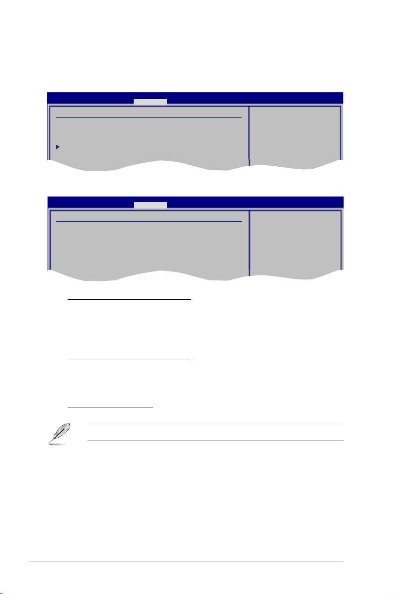
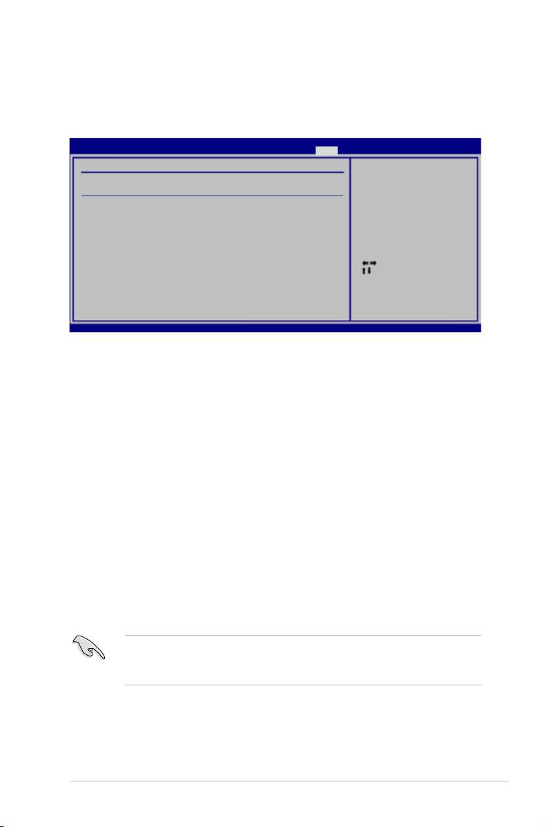
4.6 Power menu
The Power menu items allow you to change the settings for the Advanced
Power Management (APM). Select an item then press <Enter> to display the
conguration options.
BIOS SETUP UTILITY
Main Ai Tweaker Advanced Power Boot Tools Exit
Select the ACPI state
Suspend Mode [Auto]
used for System
Repost Video on S3 Resume [Disabled]
Suspend.
ACPI 2.0 Support [Disabled]
ACPI APIC Support [Enabled]
APM Conguration
Hardware Monitor
Select Screen
Select Item
+-
Change Option
F1 General Help
F10 Save and Exit
ESC Exit
v02.61 (C)Copyright 1985-2007, American Megatrends, Inc.
4.6.1 Suspend Mode [Auto]
Allows you to select the Advanced Conguration and Power Interface (ACPI) state
to be used for system suspend.
Conguration options: [S1 (POS) Only] [S3 Only] [Auto]
4.6.2 Repost Video on S3 Resume [Disabled]
Determines whether to invoke VGA BIOS POST on S3/STR resume.
Conguration options: [Disabled] [Enabled]
4.6.3 ACPI 2.0 Support [Disabled]
Add additional tables as per ACPI 2.0 specications.
Conguration options: [Disabled] [Enabled]
4.6.4 ACPI APIC Support [Enabled]
Allows you to enable or disable the Advanced Conguration and Power Interface
(ACPI) support in the Advanced Programmable Interrupt Controller (APIC). When
set to [Enabled], the ACPI APIC table pointer is included in the RSDT pointer list.
Conguration options: [Disabled] [Enabled]
4-30 Chapter 4: BIOS setup

4.6.5 APM Conguration
BIOS SETUP UTILITY
Power
APM Conguration
<Enter> to select
whether or not to
Restore on AC Power Loss [Power Off]
restart the system
after AC power loss.
Power On By RTC Alarm [Disabled]
Power On By External Modems [Disabled]
Power On By PCI Devices [Disabled]
Power On By PCIE Devices [Disabled]
Power On By PS/2 Keyboard [Disabled]
Energy Star 4.0C Support [Disabled]
Select Screen
Select Item
+-
Change Option
F1 General Help
F10 Save and Exit
ESC Exit
v02.61 (C)Copyright 1985-2007, American Megatrends, Inc.
Restore On AC Power Loss [Power Off]
When set to [Power Off], the system goes into off state after an AC power loss.
When set to [Power On], the system goes on after an AC power loss. When set to
[Last State], the system goes into either off or on state, whatever the system state
was before the AC power loss.
Conguration options: [Power Off] [Power On] [Last State]
Power On By RTC Alarm [Disabled]
Allows you to enable or disable RTC to generate a wake event. When this item
is set to [Enabled], the items RTC Alarm Date/ RTC Alarm Hour/ RTC Alarm
Minute/ RTC Alarm Second will become user-congurable with set values.
Conguration options: [Disabled] [Enabled]
Power On By External Modems [Disabled]
This allows either settings of [Enabled] or [Disabled] for powering up the computer
when the external modem receives a call while the computer is in Soft-off mode.
Conguration options: [Disabled] [Enabled]
The computer cannot receive or transmit data until the computer and
applications are fully running. Thus, connection cannot be made on the rst
try. Turning an external modem off and then back on while the computer is off
causes an initialization string that turns the system power on.
Power On By PCI Devices [Disabled]
Allows you to enable or disable the PME to wake up from S5 by PCI devices.
Conguration options: [Disabled] [Enabled]
Power On By PCIE Devices [Disabled]
Allows you to enable or disable the PCIE devices to generate a wake event.
Conguration options: [Disabled] [Enabled]
ASUS P5E3 Premium/WiFi-AP @n 4-31

Power On By PS/2 Keyboard [Disabled]
Allows you to disable the Power On by PS/2 keyboard function or set specic keys
on the PS/2 keyboard to turn on the system. This feature requires an ATX power
supply that provides at least 1A on the +5VSB lead.
Conguration options: [Disabled] [Space Bar] [Ctrl-Esc] [Power Key]
Energy Star 4.0C [Disabled]
Allows you to enable or disable the Energy Star 4.0C support. When enabled, the
PS/2 and USB device wake-up function under S3 state and the Marvell LAN, PS/2
and USB device wake-up function under S4/S5 state will not be supported, saving
more energy to pass the Energy Star 4.0C regulations.
Conguration options: [Disabled] [Enabled]
4.6.6 Hardware Monitor
BIOS SETUP UTILITY
Power
Hardware Monitor
CPU Temperature
CPU Temperature [42ºC/107.5ºF]
CPU Fan Speed [3068RPM]
CPU Fan Control [Full Speed]
MB Temperature [32ºC/89.5ºF]
Chassis Fan 1 Speed [N/A]
Chassis Fan 2 Speed [N/A]
Chassis Fan 3 Speed [N/A]
Chassis Fan 4 Speed [N/A]
Chassis Fan Controls [Full Speed]
Select Screen
CPU Voltage [ 1.264V]
Select Item
3.3V Voltage [ 3.264V]
+-
Change Field
5V Voltage [ 5.088V]
F1 General Help
12V Voltage [12.040V]
F10 Save and Exit
ESC Exit
v02.61 (C)Copyright 1985-2007, American Megatrends, Inc.
CPU Temperature [xxxºC/xxxºF]
The onboard hardware monitor automatically detects and displays the CPU
temperature. Select [Ignored] if you do not wish to display the detected
temperatures.
CPU Fan Speed [xxxxRPM] or [Ignored] / [N/A]
The onboard hardware monitor automatically detects and displays the CPU
fan speed in rotations per minute (RPM). If the fan is not connected to the
motherboard, the eld shows [N/A].
CPU Fan Control [Full Speed]
Allows you to select the CPU fan control mode.
Conguration options: [Full Speed] [Prole] [Manual] [Fix Speed]
4-32 Chapter 4: BIOS setup

The following item appears only when you set the CPU Fan Control item to
[Prole].
Fan Profile [Optimal]
Allows you to set the appropriate performance level of the ASUS Q-Fan.
When set to [Optimal], the CPU fan automatically adjusts depending on the
CPU temperature. Set this item to [Silent Mode] to minimize the fan speed for
quiet CPU fan operation or [Performance Mode] to achieve maximum CPU
fan speed.
Conguration options: [Optimal] [Silent Mode] [Performance Mode]
The following three items appear only when you set the CPU Fan Control item
to [Manual] and are adjusted by typing the desired values using the numeric
keypad and press the <Enter> key. You can also use the <+> and <-> keys to
adjust the value.
Fan Start-Up Ratio(%) [50]
Allows you to set a start-up fan speed ratio when you power on the system.
Setting a very low ratio may cause dramatical fan speed drop and trigger
warning message.
Target Temperature (°C) [50]
If the CPU temperature exceeds this target value, the CPU fan speed will be
auto-adjusted to cool down the CPU to this target temperature.
Tolerance of Temperature (°C) [02]
Allows you to set a tolerable temperature range before the CPU fan speed
increases to cool down the CPU to the target temperature.
The following item appears only when you set the CPU Fan Control item to [Fix
Speed] and is adjusted by typing the desired values using the numeric keypad
and press the <Enter> key. You can also use the <+> and <-> keys to adjust the
value.
Fan Fix Ratio(%) [50]
Allows you to set a xed fan speed ratio during system operation.
Setting a very low ratio may cause dramatical fan speed drop and trigger
warning message.
MB Temperature [xxxºC/xxxºF]
The onboard hardware monitor automatically detects and displays the
motherboard temperature. Select [Ignored] if you do not wish to display the
detected temperatures.
ASUS P5E3 Premium/WiFi-AP @n 4-33

Chassis Fan 1/2/3/4 Speed [xxxxRPM] or [Ignored] / [N/A]
The onboard hardware monitor automatically detects and displays the chassis
fan speed in rotations per minute (RPM). If the fan is not connected to the
motherboard, the eld shows [N/A].
Chassis Fan Controls [Full Speed]
Allows you to select the chassis fan control mode.
Conguration options: [Full Speed] [Manual] [Fix Speed]
The following three items appear only when you set the Chassis Fan Controls
item to [Manual] and are adjusted by typing the desired values using the
numeric keypad and press the <Enter> key. You can also use the <+> and <->
keys to adjust the value.
Fan Start-Up Ratio(%) [50]
Allows you to set a start-up fan speed ratio when you power on the system.
Setting a very low ratio may cause dramatical fan speed drop and trigger
warning message.
Target Temperature (°C) [30]
If the motherboard temperature exceeds this target value, the chassis fan
speed will be auto-adjusted to cool down the motherboard to this target
temperature.
Tolerance of Temperature (°C) [02]
Allows you to set a tolerable temperature range before the chassis fan speed
increases to cool down the motherboard to the target temperature.
The following item appears only when you set the Chassis Fan Controls item
to [Fix Speed] and is adjusted by typing the desired values using the numeric
keypad and press the <Enter> key. You can also use the <+> and <-> keys to
adjust the value.
Fan Fix Ratio(%) [50]
Allows you to set a xed fan speed ratio during system operation.
Setting a very low ratio may cause dramatical fan speed drop and trigger
warning message.
CPU Voltage, 3.3V Voltage, 5V Voltage, 12V Voltage
The onboard hardware monitor automatically detects the voltage output through
the onboard voltage regulators. Select [Ignored] if you do not want to detect this
item.
4-34 Chapter 4: BIOS setup
4.7 Boot menu
The Boot menu items allow you to change the system boot options. Select an item
then press <Enter> to display the sub-menu.
BIOS SETUP UTILITY
Main Ai Tweaker Advanced Power Boot Tools Exit
Species the Boot
Boot Device Priority
Device Boot Priority
sequence.
Boot Settings Conguration
A virtual oppy disk
Security
drive (Floppy Drive B:
) may appear when you
set the CD-ROM drive
as the rst boot
device.
Select Screen
Select Item
Enter Go to Sub Screen
F1 General Help
F10 Save and Exit
ESC Exit
v02.61 (C)Copyright 1985-2007, American Megatrends, Inc.
4.7.1 Boot Device Priority
BIOS SETUP UTILITY
Boot
Boot Device Priority
Species the boot
sequence from the
1st Boot Device [1st FLOPPY DRIVE]
availabe devices.
2nd Boot Device [Hard Drive]
3rd Boot Device [ATAPI CD-ROM]
A device enclosed
in parenthesis has
been disabled in the
corresponding menu.
Select Screen
Select Item
+-
Change Option
F1 General Help
F10 Save and Exit
ESC Exit
v02.61 (C)Copyright 1985-2007, American Megatrends, Inc.
1st ~ xxth Boot Device [xxx Drive]
These items specify the boot device priority sequence from the available devices.
The number of device items that appears on the screen depends on the number of
devices installed in the system.
Conguration options: [1st FLOPPY DRIVE] [Hard Drive] [ATAPI CD-ROM]
[Disabled]
ASUS P5E3 Premium/WiFi-AP @n 4-35

4.7.2 Boot Settings Conguration
BIOS SETUP UTILITY
Boot
Boot Settings Conguration
Allows BIOS to skip
certain tests while
Quick Boot [Enabled]
booting. This will
Full Screen Logo [Enabled]
decrease the time needed
AddOn ROM Display Mode [Force BIOS]
to boot the system.
Bootup Num-Lock [On]
Wait for ‘F1’ if Error [Enabled]
Hit ‘DEL’ Message Display [Enabled]
Interrupt 19 Capture [Disabled]
Select Screen
Select Item
+-
Change Option
F1 General Help
F10 Save and Exit
ESC Exit
v02.61 (C)Copyright 1985-2007, American Megatrends, Inc.
Quick Boot [Enabled]
Enabling this item allows the BIOS to skip some power on self tests (POST) while
booting to decrease the time needed to boot the system. When set to [Disabled],
BIOS performs all the POST items. Conguration options: [Disabled] [Enabled]
Full Screen Logo [Enabled]
This allows you to enable or disable the full screen logo display feature.
Conguration options: [Disabled] [Enabled]
Set this item to [Enabled] to use the ASUS MyLogo3™ feature.
AddOn ROM Display Mode [Force BIOS]
Sets the display mode for option ROM.
Conguration options: [Force BIOS] [Keep Current]
Bootup Num-Lock [On]
Allows you to select the power-on state for the NumLock.
Conguration options: [Off] [On]
Wait for ‘F1’ If Error [Enabled]
When set to [Enabled], the system waits for the <F1> key to be pressed when error
occurs. Conguration options: [Disabled] [Enabled]
Hit ‘DEL’ Message Display [Enabled]
When set to [Enabled], the system displays the message “Press DEL to run Setup”
during POST. Conguration options: [Disabled] [Enabled]
Interrupt 19 Capture [Disabled]
When set to [Enabled], this function allows the option ROMs to trap Interrupt 19.
Conguration options: [Disabled] [Enabled]
4-36 Chapter 4: BIOS setup
4.7.3 Security
The Security menu items allow you to change the system security settings. Select
an item then press <Enter> to display the conguration options.
BIOS SETUP UTILITY
Boot
Security Settings
<Enter> to change
password.
Supervisor Password : Not Installed
<Enter> again to
User Password : Not Installed
disabled password.
Change Supervisor Password
Change User Password
Select Screen
Select Item
Enter Change
F1 General Help
F10 Save and Exit
ESC Exit
v02.61 (C)Copyright 1985-2007, American Megatrends, Inc.
Change Supervisor Password
Select this item to set or change the supervisor password. The Supervisor
Password item on top of the screen shows the default Not Installed. After you set
a password, this item shows Installed.
To set a Supervisor Password:
1. Select the
Change Supervisor Password item and press <Enter>.
2. From the password box, type a password composed of at least six letters
and/or numbers, then press <Enter>.
3. Conrm the password when prompted.
The message “Password Installed” appears after you successfully set your
password.
To change the supervisor password, follow the same steps as in setting a user
password.
To clear the supervisor password, select the Change Supervisor Password then
press <Enter>. The message “Password Uninstalled” appears.
If you forget your BIOS password, you can clear it by erasing the CMOS Real
Time Clock (RTC) RAM. See section 2.6 Jumper for information on how to
erase the RTC RAM.
After you have set a supervisor password, the other items appear to allow you to
change other security settings.
ASUS P5E3 Premium/WiFi-AP @n 4-37

BIOS SETUP UTILITY
Boot
Security Settings
<Enter> to change
password.
Supervisor Password : Installed
<Enter> again to
User Password : Installed
disabled password.
Change Supervisor Password
User Access Level [Full Access]
Change User Password
Clear User Password
Password Check [Setup]
Select Screen
Select Item
Enter Change
F1 General Help
F10 Save and Exit
ESC Exit
v02.61 (C)Copyright 1985-2007, American Megatrends, Inc.
User Access Level [Full Access]
This item allows you to select the access restriction to the Setup items.
Conguration options: [No Access] [View Only] [Limited] [Full Access]
[No Access] prevents user access to the Setup utility.
[View Only] allows access but does not allow change to any eld.
[Limited] allows changes only to selected elds, such as Date and Time.
[Full Access] allows viewing and changing all the elds in the Setup utility.
Change User Password
Select this item to set or change the user password. The User Password item on
top of the screen shows the default Not Installed. After you set a password, this
item shows Installed.
To set a User Password:
1. Select the
Change User Password item and press <Enter>.
2. On the password box that appears, type a password composed of at least six
letters and/or numbers, then press <Enter>.
3. Conrm the password when prompted.
The message “Password Installed” appears after you set your password
successfully.
To change the user password, follow the same steps as in setting a user password.
Clear User Password
Select this item to clear the user password.
Password Check [Setup]
When set to [Setup], BIOS checks for user password when accessing the Setup
utility. When set to [Always], BIOS checks for user password both when accessing
Setup and booting the system. Conguration options: [Setup] [Always]
4-38 Chapter 4: BIOS setup
4.8 Tools menu
The Tools menu items allow you to congure options for special functions. Select
an item then press <Enter> to display the sub-menu.
BIOS SETUP UTILITY
Main Ai Tweaker Advanced Power Boot Tools Exit
ASUS EZ Flash 2
Press ENTER to run
ASUS Express Gate [Enabled]
the utility to select
Reset User Data [No]
and update BIOS.
Time Out [10]
This utility doesn't
support :
ASUS O.C. Prole
1.NTFS format
Ai Net 2
Select Screen
Select Item
+-
Change Field
Enter Go to Sub Screen
F1 General Help
F10 Save and Exit
ESC Exit
v02.61 (C)Copyright 1985-2007, American Megatrends, Inc.
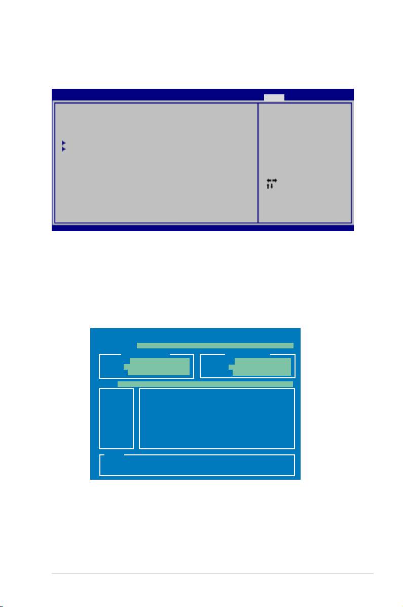
4.8.1 ASUS EZ Flash 2
Allows you to run ASUS EZ Flash 2. When you press <Enter>, a conrmation
message appears. Use the left/right arrow key to select between [Yes] or [No],
then press <Enter> to conrm your choice. Please see page 4-4, section 4.1.2 for
details.
ASUSTek EZ Flash 2 BIOS ROM Utility V3.06
FLASH TYPE: MXIC 25L1605A
Current ROM
Update ROM
BOARD: P5E3 Premium
BOARD: Unknown
VER: 0110
VER: Unknown
DATE: 11/08/07
DATE: Unknown
PATH: A:\
A:
Note
[Enter] Select or Load [B] Backup [ESC] Exit
[Tab] Switch [Up/Down/Home/End] Move
ASUS P5E3 Premium/WiFi-AP @n 4-39

4.8.2 ASUS Express Gate
Allows you to enable or disable the ASUS Express Gate feature. The ASUS
Express Gate feature is a unique instant-on environment that provides quick
access to the Internet browser and Skype. Refer to section 5.3.11 for details.
Conguration options: [Enabled] [Disabled]
Reset User Data [No]
Allows you to clear Express Gate’s user data.
Conguration options: [No] [Reset]
When setting this item to [Reset], make sure to save the setting to the BIOS
so that the user data will be cleared the next time you enter the Express
Gate. User data includes the Express Gate’s settings as well as any personal
information stored by the web browser (bookmarks, cookies, browsing
history, etc.). This is useful in the rare case where corrupt settings prevent the
Express Gate environment from launching properly.
The rst time wizard will run again when you enter the Express Gate
environment after clearing its settings.
Timeout [10]
Sets the amount of time the system waits at the Express Gate’s rst screen
before defaulting to starting Windows or other installed OS. Entering [0]
means waiting indenitely at the rst screen for user action.
Conguration options: [0 second] ~ [30 seconds]
The time length is adjusted by typing the desired values using the numeric
keypad and press the <Enter> key.
4-40 Chapter 4: BIOS setup
4.8.3 ASUS O.C. Prole
This item allows you to store or load multiple BIOS settings.
BIOS SETUP UTILITY
Tools
O.C. PROFILE Conguration
Save to Prole 1
O.C. Prole 1 Status : Not Installed
O.C. Prole 2 Status : Not Installed
Save to Prole 1
Load from Prole 1
Save to Prole 2
Load from Prole 2
Start O.C. Prole
Select Screen
Select Item
Enter Go to Sub Screen
F1 General Help
F10 Save and Exit
ESC Exit
v02.61 (C)Copyright 1985-2007, American Megatrends, Inc.
Save to Proe 1/2
Allows you to save the current BIOS le to the BIOS Flash. Press <Enter> to save
the le.
Load from Prole 1/2
Allows you to load the previous BIOS settings saved in the BIOS Flash. Press
<Enter> to load the le.
Start O.C. Prole
Allows you to run the utility to save and load CMOS. Press <Enter> to run the
utility.
ASUSTek O.C. Prole Utility V1.06
Current CMOS
Restore CMOS
BOARD: P5E3 Premium
BOARD: Unknown
VER: 0110
VER: Unknown
DATE: 11/08/07
DATE: Unknown
PATH: A:\
A:
Note
[Enter] Select or Load [B] Backup [ESC] Exit
[Tab] Switch [Up/Down/Home/End] Move
• This function can support devices such as a USB ash disk or a oppy
disk with FAT 32/16 format and single partition only.
• DO NOT shut down or reset the system while updating the BIOS to
prevent the system boot failure!
ASUS P5E3 Premium/WiFi-AP @n 4-41

4.8.4 Ai Net 2
BIOS SETUP UTILITY
Tools
Pair Status Length
Marvell Check LAN
cable during POST.
1-2 N/A Marvell Controller 0
3-6 N/A
4-5 N/A
7-8 N/A
1-2 N/A Realtek Controller 0
3-6 N/A
ASUSTek O.C. Prole Utility V1.06
4-5 N/A
7-8 N/A
Marvell POST Check LAN cable [Disabled]
Realtek POST Check LAN cable [Disabled]
v02.61 (C)Copyright 1985-2007, American Megatrends, Inc.
Marvell POST Check LAN Cable [Disabled]
Enables or disables checking of the Marvell LAN cable during the Power-On
Self-Test (POST).
Conguration options: [Disabled] [Enabled]
Realtek POST Check LAN Cable [Disabled]
Enables or disables checking of the Realtek LAN cable during the Power-On
Self-Test (POST).
Conguration options: [Disabled] [Enabled]
4-42 Chapter 4: BIOS setup

4.9 Exit menu
The Exit menu items allow you to load the optimal or failsafe default values for the
BIOS items, and save or discard your changes to the BIOS items.
BIOS SETUP UTILITY
Main Ai Tweaker Advanced Power Boot Tools Exit
Exit system setup
Exit & Save Changes
after saving the
Exit & Discard Changes
changes.
Discard Changes
F10 key can be used
Load Setup Defaults
for this operation.
Select Screen
Select Item
Enter Go to Sub Screen
F1 General Help
F10 Save and Exit
ESC Exit
v02.61 (C)Copyright 1985-2007, American Megatrends, Inc.
Pressing <Esc> does not immediately exit this menu. Select one of the options
from this menu or <F10> from the legend bar to exit.
Exit & Save Changes
Once you are nished making your selections, choose this option from the Exit
menu to ensure the values you selected are saved to the CMOS RAM. An onboard
backup battery sustains the CMOS RAM so it stays on even when the PC is turned
off. When you select this option, a conrmation window appears. Select Ok to save
changes and exit.
If you attempt to exit the Setup program without saving your changes, the
program prompts you with a message asking if you want to save your changes
before exiting. Press <Enter> to save the changes while exiting.
Exit & Discard Changes
Select this option only if you do not want to save the changes that you made to
the Setup program. If you made changes to elds other than System Date, System
Time, and Password, the BIOS asks for a conrmation before exiting.
Discard Changes
This option allows you to discard the selections you made and restore the
previously saved values. After selecting this option, a conrmation appears. Select
Ok to discard any changes and load the previously saved values.
Load Setup Defaults
This option allows you to load the default values for each of the parameters on the
Setup menus. When you select this option or if you press <F5>, a conrmation
window appears. Select Ok to load default values. Select Exit & Save Changes or
make other changes before saving the values to the non-volatile RAM.
ASUS P5E3 Premium/WiFi-AP @n 4-43

4-44 Chapter 4: BIOS setup
