Asus P5E3 Premium WiFi-AP@n: Software
Software: Asus P5E3 Premium WiFi-AP@n

This chapter describes the contents of
the support DVD that comes with the
motherboard package and the softwares.
Software
5
support

Chapter summary
5
5.1 Installing an operating system ................................................... 5-1
5.2 Support DVD information ............................................................
5-1
5.3 Software information ...................................................................
5-9
5.4
RAID congurations .................................................................. 5-42
5.5 Creating a RAID driver disk .......................................................
5-59
ASUS P5E3 Premium/WiFi-AP @n
5.1 Installing an operating system
®
This motherboard supports Windows
XP/ 64-bit XP/ Vista™ operating systems
(OS). Always install the latest OS version and corresponding updates to maximize
the features of your hardware.
• Motherboard settings and hardware options vary. Use the setup
procedures presented in this chapter for reference only. Refer to your OS
documentation for detailed information.
®
• Make sure that you install the Windows
XP Service Pack 2 or later
versions before installing the drivers for better compatibility and system
stability.
5.2 Support DVD information
The support DVD that came with the motherboard package contains the drivers,
software applications, and utilities that you can install to avail all motherboard
features.
The contents of the support DVD are subject to change at any time without
notice. Visit the ASUS website(www.asus.com) for updates.
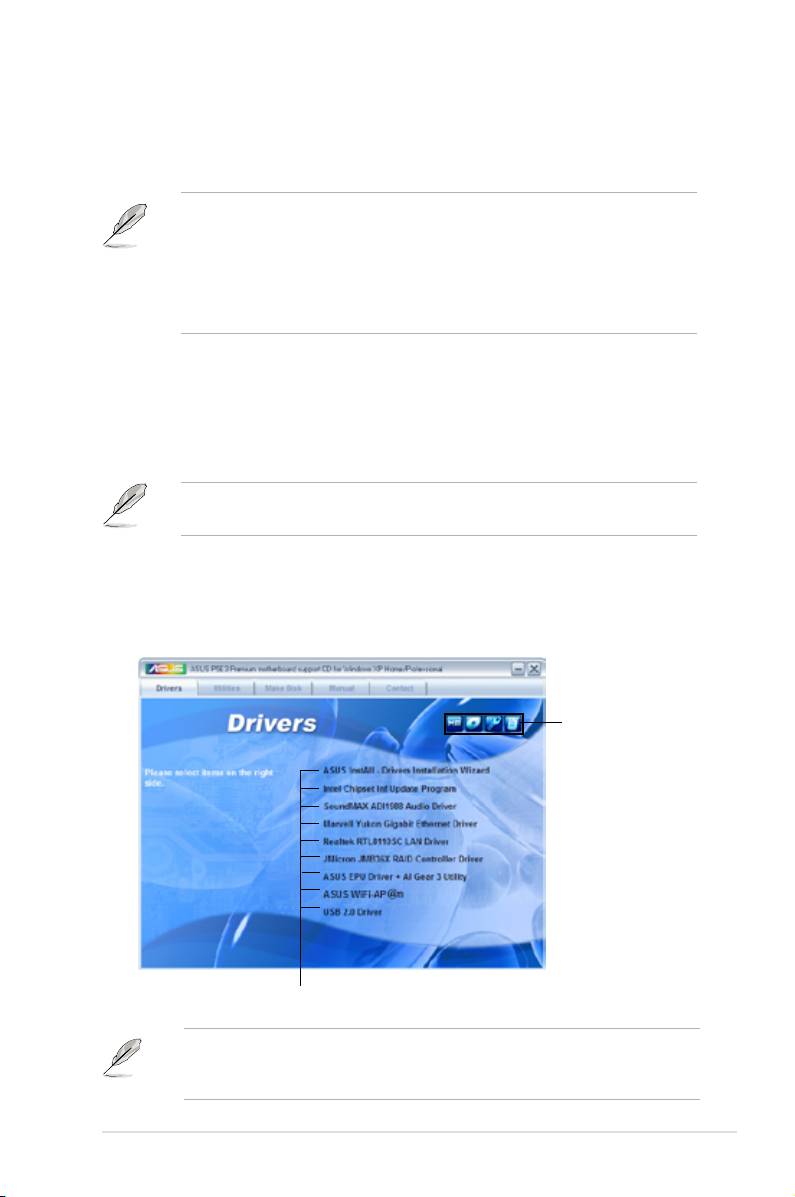
5.2.1 Running the support DVD
Place the support DVD to the optical drive. The DVD automatically displays the
Drivers menu if Autorun is enabled in your computer.
Click an icon to
display support DVD/
motherboard information
Click an item to install
If Autorun is NOT enabled in your computer, browse the contents of the support
DVD to locate the le ASSETUP.EXE from the BIN folder. Double-click the
ASSETUP.EXE to run the DVD.
ASUS P5E3 Premium/WiFi-AP @n 5-1

5.2.2 Drivers menu
The Drivers menu shows the available device drivers if the system detects installed
devices. Install the necessary drivers to activate the devices.
ASUS InstAll - Drivers Installation Wizard
Installs all of the drivers through the Installation Wizard.
Intel Chipset Inf Update Program
®
Installs the Intel
chipset Inf update program.
SoundMAX ADI1988 Audio Driver
®
Installs the SoundMAX
ADI1988 audio driver and application.
Marvell Yukon Gigabit Ethernet Driver
Installs the Marvell Yukon Gigabit Ethernet driver.
Realtek RTL8110SC LAN Driver
Installs the Realtek RTL8110SC LAN driver.
JMicro JMB36X RAID Controller Driver
®
Installs the JMicro
JMB36X RAID controller driver.
ASUS EPU Driver + AI Gear 3 Utility
Installs the EPU + AI Gear 3 driver.
Install this driver before the ASUS AI Suite utility.
ASUS WiFi-AP @n
Installs the ASUS WiFi-AP @n driver.
USB 2.0 Driver
Installs the USB 2.0 driver.
5-2 Chapter 5: Software support
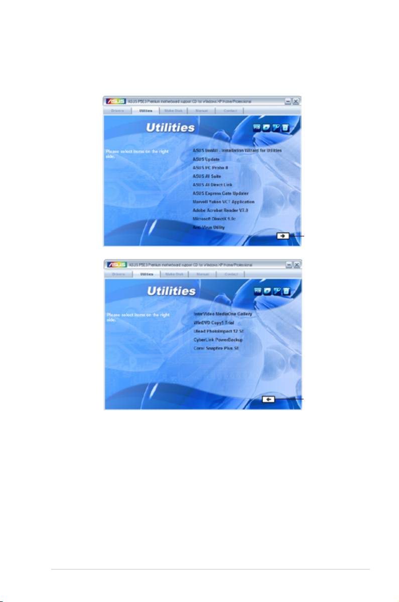
5.2.3 Utilities menu
The Utilities menu shows the applications and other software that the motherboard
supports.
Click to display
the next page
Click to return
to the previous
page
ASUS InstAll - Installation Wizard for Utilities
Installs all of the utilities through the Installation Wizard.
ASUS Update
®
The ASUS Update utility allows you to update the motherboard BIOS in Windows
environment. This utility requires an Internet connection either through a network
or an Internet Service Provider (ISP).
ASUS PC Probe II
This smart utility monitors the fan speed, CPU temperature, and system voltages,
and alerts you of any detected problems. This utility helps you keep your computer
in healthy operating condition.
ASUS P5E3 Premium/WiFi-AP @n 5-3

ASUS AI Suite
Installs the ASUS AI Suite.
ASUS AI Direct Link
Installs the ASUS AI Direct Link application
ASUS Express Gate Updater
Installs the ASUS Express Gate™ update application.
Marvell Yukon VCT Application
®
Installs the Marvell
Yukon Virtual Cable Tester™ (VCT) application that
diagnoses and reports LAN cable faults and shorts using the Time Domain
Reectometry (TDR) technology.
Adobe Acrobat Reader V7.0
®
®
Installs the Adobe
Acrobat
Reader that allows you to open, view, and print
documents in Portable Document Format (PDF).
Microsoft DirectX 9.0c
®
®
Installs the Microsoft
DirectX 9.0c driver. The Microsoft DirectX
9.0c is a
®
multimedia technology that enhances computer graphics and sound. DirectX
improves the multimedia features of you computer so you can enjoy watching
TV and movies, capturing videos, or playing games in your computer. Visit
the Microsoft website (www.microsoft.com) for updates.
Anti-Virus Utility
The anti-virus application scans, identies, and removes computer viruses.
View the online help for detailed information.
InterVideo MediaOne Gallery
Installs the media library and all-in-one software.
WinDVD Copy5 Trial
Installs the WinDVD Copy5 trial version.
Ulead PhotoImpact 12 SE
Installs the PhotoImpact image editing software.
CyberLink PowerBackup
Installs CyberLink PowerBackup to back up and restore your data easily.
Corel Snapre Plus SE
Installs Corel Snapre Plus SE.
5-4 Chapter 5: Software support

5.2.4 Make disk menu
®
The Make disk menu contains items to create the Intel ICH9 or JMicron
JMB36X
RAID/AHCI driver disk.
Intel ICH9 32/64bit RAID/AHCI Driver Disk
Allows you to create an ICH9 32/64bit RAID/AHCI driver disk.
JMicron JMB36X 32/64bit RAID Driver
®
Allows you to create a JMicron
JMB36X 32/64bit RAID driver.
ASUS P5E3 Premium/WiFi-AP @n 5-5
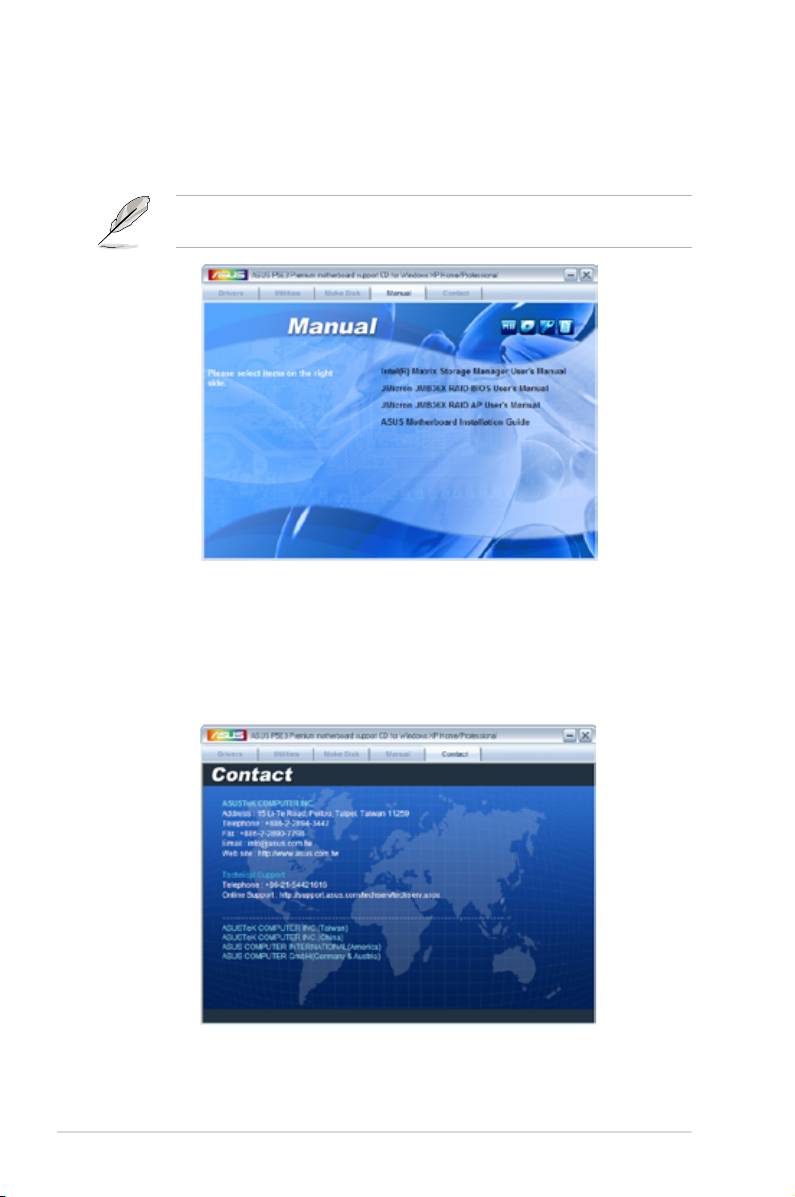
5.2.5 Manual menu
The Manual menu contains a list of supplementary user manuals. Click an item to
open the folder of the user manual.
®
Most user manual les are in Portable Document Format (PDF). Install the Adobe
®
Acrobat
Reader from the Utilities menu before opening a user manual le.
5.2.6 ASUS Contact information
Click the Contact tab to display the ASUS contact information. You can also nd
this information on the inside front cover of this user guide.
5-6 Chapter 5: Software support
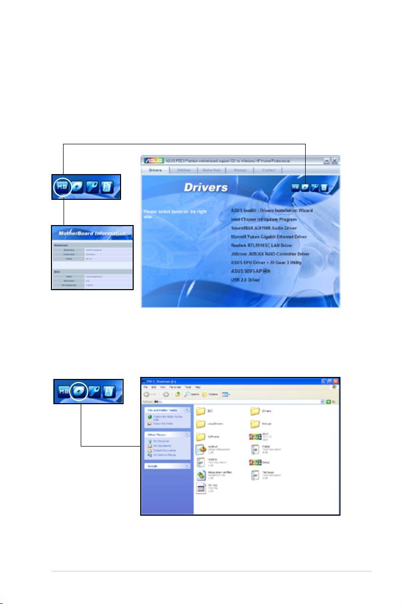
5.2.7 Other information
The icons on the top right corner of the screen give additional information on the
motherboard and the contents of the support DVD. Click an icon to display the
specied information.
Motherboard Info
Displays the general specications of the motherboard.
Browse this DVD
Displays the support DVD contents in graphical format.
ASUS P5E3 Premium/WiFi-AP @n 5-7
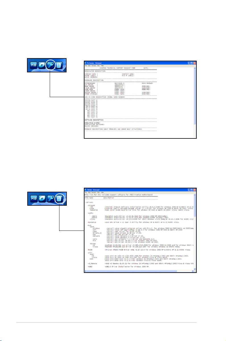
Technical support Form
Displays the ASUS Technical Support Request Form that you have to ll out when
requesting technical support.
Filelist
Displays the contents of the support DVD in text format.
5-8 Chapter 5: Software support

5.3 Software information
Most of the applications in the support DVD have wizards that will conveniently
guide you through the installation. View the online help or readme le that came
with the software application for more information.
5.3.1 ASUS MyLogo3™
The ASUS MyLogo3™ utility lets you customize the boot logo. The boot logo is the
image that appears on screen during the Power-On-Self-Tests (POST). The ASUS
MyLogo3™ is automatically installed when you install the ASUS Update utility from
the support DVD. See section
5.2.3 Utilities menu
for details.
• Before using the ASUS MyLogo3™, use the AFUDOS utility to make a copy
of your original BIOS le, or obtain the latest BIOS version from the ASUS
website. See section 4.1.4 AFUDOS utility.
• Make sure that the BIOS item Full Screen Logo is set to [Enabled] if
you wish to use ASUS MyLogo3. See section 4.7.2 Boot Settings
Conguration.
• You can create your own boot logo image in GIF, JPG, or BMP le formats.
To launch the ASUS MyLogo3™:
1. Launch the ASUS Update utility. Refer to section
4.1.1 ASUS Update utility
for details.
2. Select
Options
from the drop down menu, then click
Next
.
3. Check the option
Launch MyLogo
to replace system boot logo before
ashing BIOS, then click
Next
.
4. Select
Update BIOS from a le
from the drop down menu, then click
Next
.
5. When prompted, locate the new BIOS le, then click
Next
. The ASUS
MyLogo3 window appears.
6. From the left window pane, select
the folder that contains the image
you intend to use as your boot logo.
ASUS P5E3 Premium/WiFi-AP @n 5-9

7. When the logo images appear on the
right window pane, select an image to
enlarge by clicking on it.
8. Adjust the boot image to your desired
size by selecting a value on the Ratio
box.
9. When the screen returns to the ASUS Update utility, ash the original BIOS to
load the new boot logo.
10. After ashing the BIOS, restart the computer to display the new boot logo
during POST.
5-10 Chapter 5: Software support
5.3.2 AI NET2
®
The AI NET2 features the Marvell
Virtual Cable Tester™ (VCT). VCT is a cable
diagnostic utility that reports LAN cable faults and shorts using the Time Domain
Reectometry (TDR) technology. The VCT detects and reports open and shorted
cables, impedance mismatches, pair swaps, pair polarity problems, and pair skew
problems of up to 64 ns at one meter accuracy.
The VCT feature reduces networking and support costs through a highly
manageable and controlled network system. This utility can be incorporated
in the network systems sofware for ideal eld support as well as development
diagnostics.
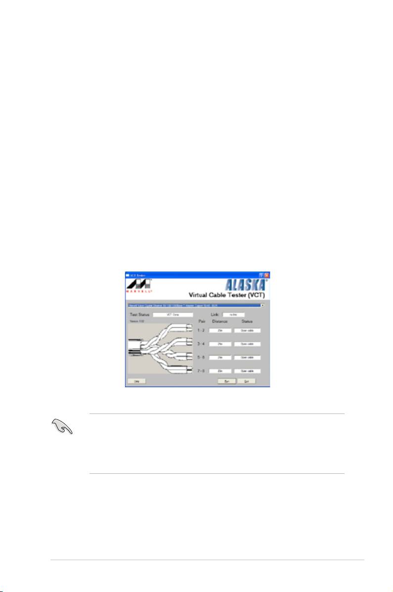
Using the Virtual Cable Tester™
®
To use the the Marvell
Virtual Cable Tester™ utility:
®
1. Launch the VCT utility from the Windows
desktop by clicking
Start
>
All
Programs
>
Marvell
>
Virtual Cable Tester
.
2. Click
Virtual Cable Tester
from the menu to display the screen below.
3. Click the
Run
button to perform a cable test.
• The VCT utility only tests Ethernet cables connected to Gigabit LAN port(s).
• The Run button on the Virtual Cable Tester™ main window is disabled if no
problem is detected on the LAN cable(s) connected to the LAN port(s).
• If you want the system to check the status of the LAN cable before entering
the OS, enable the item Post Check LAN Cable in the BIOS Setup.
ASUS P5E3 Premium/WiFi-AP @n 5-11

5.3.3 ASUS PC Probe II
PC Probe II is a utility that monitors the computer’s vital components, and detects
and alerts you of any problem with these components. PC Probe II senses fan
rotations, CPU temperature, and system voltages, among others. Because PC
Probe II is software-based, you can start monitoring your computer the moment
you turn it on. With this utility, you are assured that your computer is always at a
healthy operating condition.
Installing PC Probe II
To install PC Probe II on your computer:
1. Place the support DVD to the optical drive. The Drivers installation tab
appears if your computer has an enabled Autorun feature.
If Autorun is not enabled in your computer, browse the contents of the support
DVD to locate the setup.exe le from the ASUS PC Probe II folder. Double-click
the setup.exe le to start installation.
2. Click the Utilities tab, then click ASUS PC Probe II.
3. Follow the screen instructions to complete installation.
Launching PC Probe II
You can launch the PC Probe II right after installation or anytime from the
®
Windows
desktop.
®
To launch the PC Probe II from the Windows
desktop, click
Start > All Programs
> ASUS > PC Probe II > PC Probe II v1.xx.xx
. The PC Probe II main window
appears.
®
After launching the application, the PC Probe II icon appears in the Windows
taskbar. Click this icon to close or restore the application.
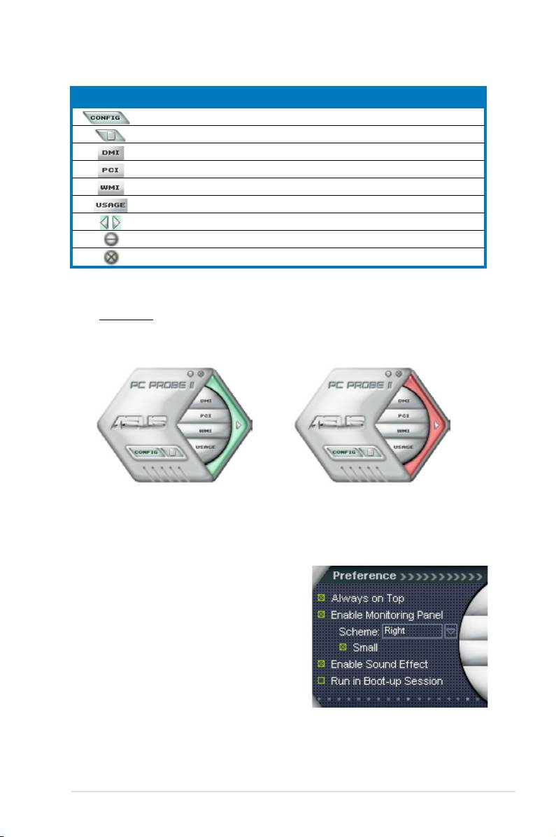
Using PC Probe II
Main window
The PC Probe II main window allows you to view the current status of your
system and change the utility
conguration. By default, the main
window displays the Preference
section. You can close or restore
the Preference section by clicking
on the triangle on the main
window right handle.
Click to close the
Preference panel
5-12 Chapter 5: Software support
Button Function
Opens the Conguration window
Opens the Report window
Opens the Desktop Management Interface window
Opens the Peripheral Component Interconnect window
Opens the Windows Management Instrumentation window
Opens the hard disk drive, memory, CPU usage window
Shows/Hides the Preference section
Minimizes the application
Closes the application
Sensor alert
When a system sensor detects a problem, the main window right handle
turns red, as the illustrations below show.
When displayed, the monitor panel for that sensor also turns red. Refer to the
Monitor panels section for details.
Preferences
You can customize the application using the
Preference section in the main window. Click
the box before each preference to activate or
deactivate.
ASUS P5E3 Premium/WiFi-AP @n 5-13
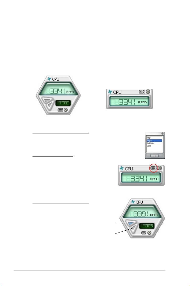
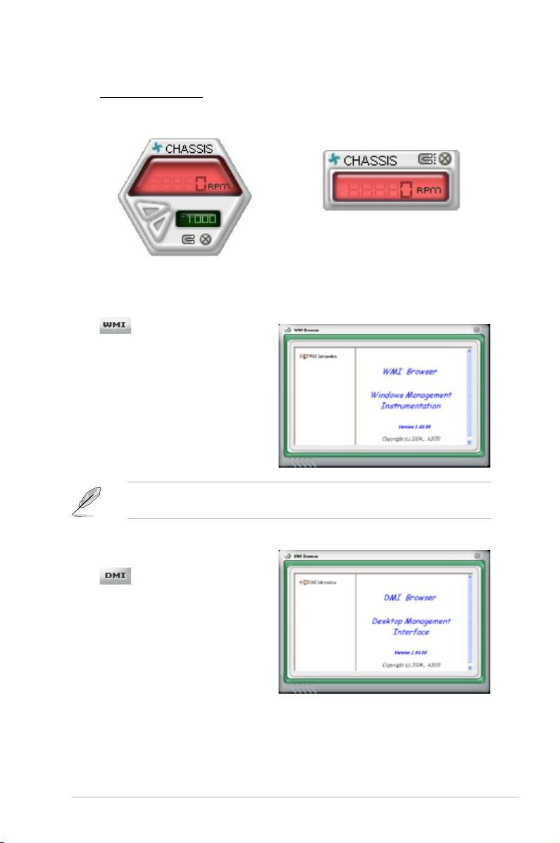
Hardware monitor panels
The hardware monitor panels display the current value of a system sensor such as
fan rotation, CPU temperature, and voltages.
The hardware monitor panels come in two display modes: hexagonal (large) and
rectangular (small). When you check the Enable Monitoring Panel option from the
Preference section, the monitor panels appear on your computer’s desktop.
Small display
Large display
Changing the monitor panels position
To change the position of the monitor panels in the desktop,
click the arrow down button of the Scheme options, then select
another position from the list box. Click OK when nished.
Moving the monitor panels
All monitor panels move together using a magnetic effect. If
you want to detach a monitor panel from
the group, click the horseshoe magnet
icon. You can now move or reposition the
panel independently.
Adjusting the sensor threshold value
You can adjust the sensor threshold
value in the monitor panel by
clicking the or buttons. You can
Click to
increase
also adjust the threshold values
value
using the Cong window.
Click to
You cannot adjust the sensor
decrease
threshold values in a small
value
monitoring panel.
5-14 Chapter 5: Software support
Monitoring sensor alert
The monitor panel turns red when a component value exceeds or is lower
than the threshold value. Refer to the illustrations below.
Small display
Large display
WMI browser
Click to display the
WMI (Windows Management
Instrumentation) browser. This
®
browser displays various Windows
management information. Click an
item from the left panel to display on
the right panel. Click the plus sign (+)
before WMI Information to display the
available information.
You can enlarge or reduce the browser size by dragging the bottom right corner
of the browser.
DMI browser
Click to display the DMI
(Desktop Management Interface)
browser. This browser displays various
desktop and system information.
Click the plus sign (+) before DMI
Information to display the available
information.
ASUS P5E3 Premium/WiFi-AP @n 5-15
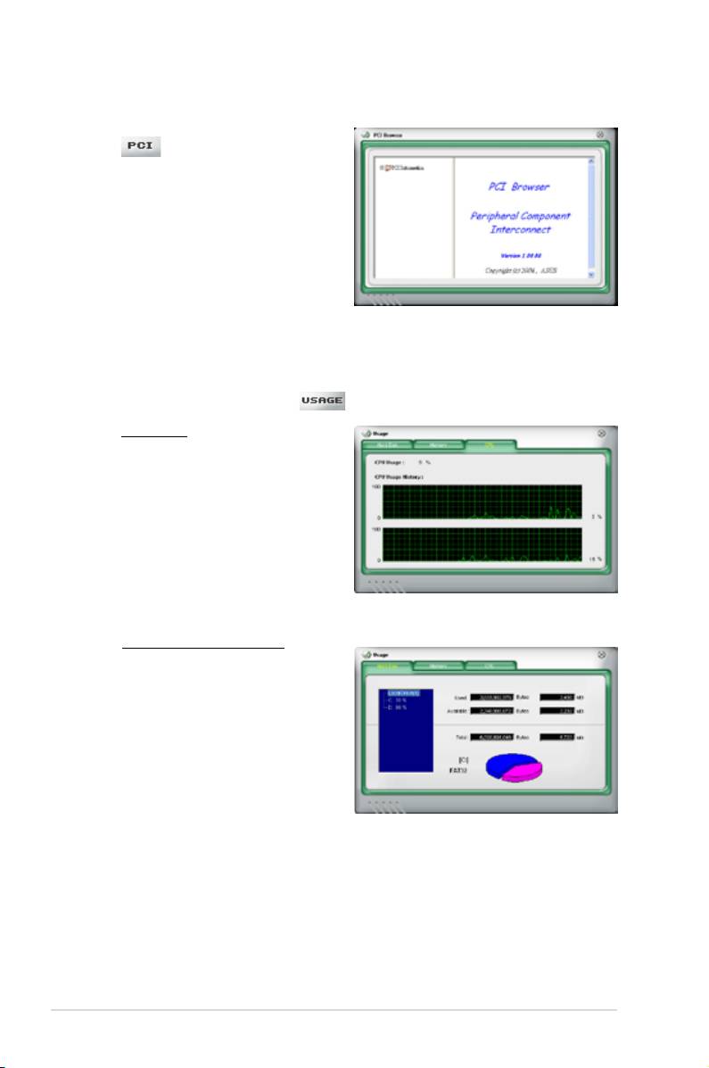
PCI browser
Click to display the PCI
(Peripheral Component Interconnect)
browser. This browser provides
information on the PCI devices installed
on your system. Click the plus sign
(+) before the PCI Information item to
display available information.
Usage
The Usage browser displays real-time information on the CPU, hard disk drive
space, and memory usage. Click to display the Usage browser.
CPU usage
The CPU tab displays real-
time CPU usage in line graph
representation. If the CPU has
an enabled Hyper-Threading,
two separate line graphs display
the operation of the two logical
processors.
Hard disk drive space usage
The Hard Disk tab displays the
used and available hard disk
drive space. The left panel of the
tab lists all logical drives. Click
a hard disk drive to display the
information on the right panel.
The pie chart at the bottom of the
window represents the used (blue)
and the available HDD space.
5-16 Chapter 5: Software support
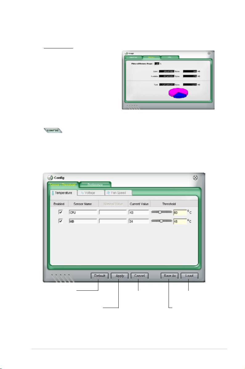
Memory usage
The Memory tab shows both
used and available physical
memory. The pie chart at the
bottom of the window represents
the used (blue) and the available
physical memory.
Conguring PC Probe II
Click to view and adjust the sensor threshold values.
The Cong window has two tabs: Sensor/Threshold and Preference. The Sensor/
Threshold tab enables you to activate the sensors or to adjust the sensor threshold
values. The Preference tab allows you to customize sensor alerts, or change the
temperature scale.
Loads the default
threshold values for
Cancels or
Loads your saved
each sensor
ignores your
conguration
changes
Applies your
Saves your
changes
conguration
ASUS P5E3 Premium/WiFi-AP @n 5-17

5.3.4 ASUS AI Suite
ASUS AI Suite allows you to launch AI Gear 3, AI N.O.S., AI Booster, AI Nap, and
Q-Fan 2 utilities easily.
Install the ASUS EPU + AI Gear 3 Driver before the ASUS AI Suite utility.
Otherwise, the ASUS AI Suite will not function properly.
Installing AI Suite
To install AI Suite on your computer:
1. Place the support DVD to the optical drive. The Drivers installation tab
appears if your computer has an enabled Autorun feature.
2. Click the Utilities tab, then click
AI Suite.
3. Follow the screen instructions to complete installation.
Launching AI Suite
®
You can launch AI Suite right after installation or anytime from the Windows
desktop.
®
To launch AI Suite from the Windows
desktop, click Start > All Programs >
ASUS > AI Suite > AI Suite v1.xx.xx. The AI Suite main window appears.
®
After launching the application, the AI Suite icon appears in the Windows
taskbar.
Click this icon to close or restore the application.
Using AI Suite
Click the AI Gear 3, AI Nap, AI Booster, or Q-Fan 2 icon to launch the utility, or click
the Normal icon to restore the system to normal state.
Press to restore to normal
Press to launch AI Nap
Press to launch AI Gear 3
Press to launch Q-Fan 2
Press to launch AI Booster
5-18 Chapter 5: Software support
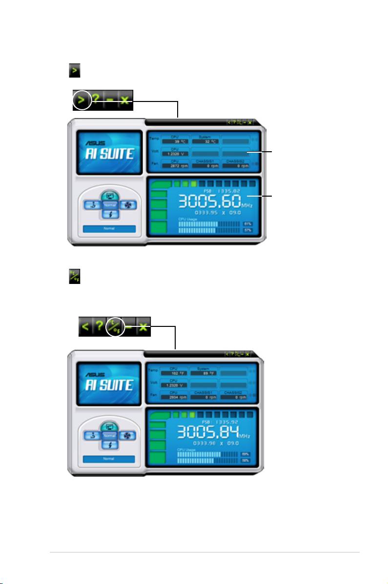
Other feature buttons
Click on right corner of the main window to open the monitor window.
Displays the CPU/
system temperature,
CPU/memory/PCIE
voltage, and CPU/
chassis fan speed
Displays the FSB/CPU
frequency
Click on right corner of the expanded window to switch the temperature from
degrees Centigrade to degrees Fahrenheit.
ASUS P5E3 Premium/WiFi-AP @n 5-19
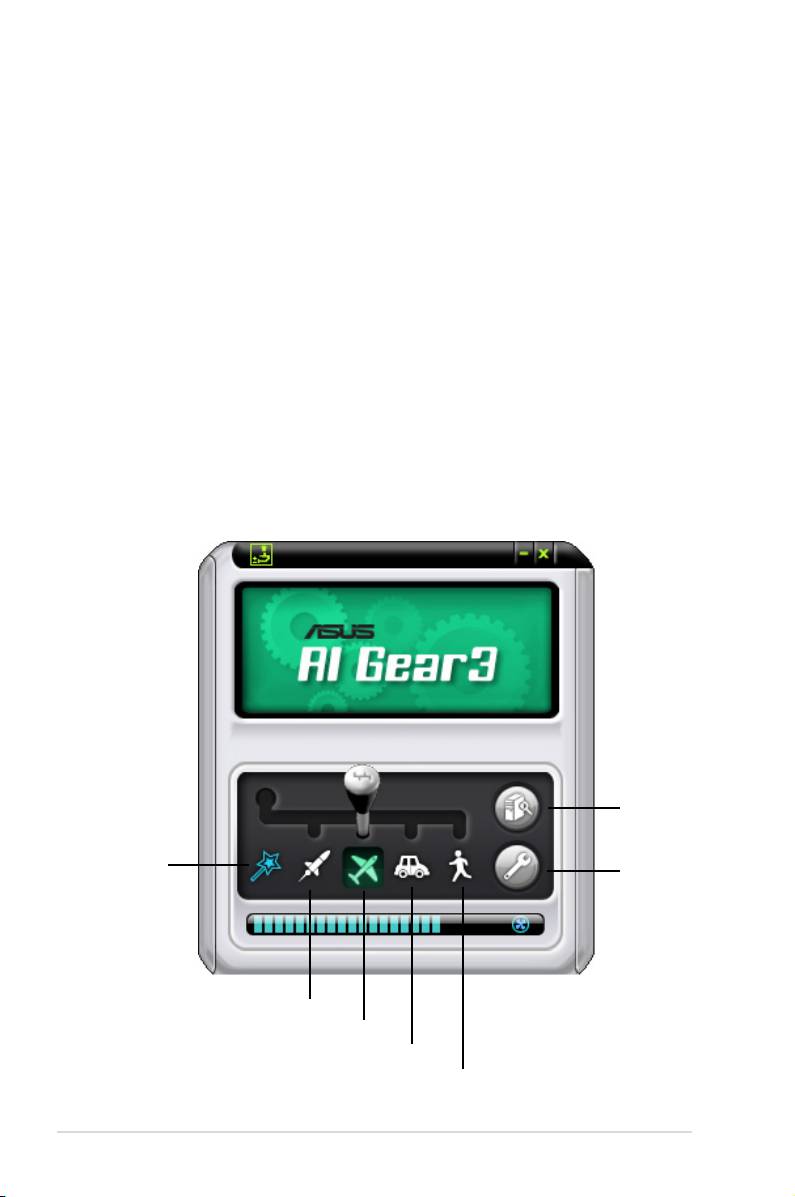
5.3.5 ASUS EPU Utility -- AI Gear 3
ASUS AI Gear 3 is a utility designed to congure and support all ASUS EPU
(Energy Processing Unit) features. This easy-to-use utility provides four system
performance proles that adjusts the processor frequency and vCore voltage for
different computing needs.
After installing ASUS AI Suite from the bundled support DVD, you can launch
ASUS AI Gear 3 by double-clicking the AI Suite icon on your Windows OS taskbar
and then click the AI Gear 3 button on the AI Suite main window.
Here are some simple ways to use AI Gear 3:
• Click the four gear mode buttons below, including
Turbo, High Performance,
Medium Power Saving, and Max. Power Saving, or shift the gear to the
performance setting that you like.
• Click
Calibration rst, and switch to Auto mode to have AI Gear 3
automatically adjust the system performance according to the CPU loading.
• Under
Auto mode, Click Settings to set the time for the system to enter AI
Nap mode.
Calibration
Auto Mode
Settings
Turbo Mode
High Performance Mode
Medium Power Saving Mode
Max. Power Saving Mode
5-20 Chapter 5: Software support

5.3.6 ASUS AI Nap
This feature allows you to minimize the power consumption of your computer
whenever you are away. Enable this feature for minimum power consumption and
a more quiet system operation.
After installing AI Suite from the bundled support DVD, you can launch the utility by
double-clicking the AI Suite icon on the Windows OS taskbar and click the AI Nap
button on the AI Suite main window.
Click Yes on the conrmation screen.
To exit AI Nap mode, press the system power or mouse button then click Yes on
the conrmation screen.
To switch the power button functions from AI Nap to shutting down, just right
click the AI Suite icon on the OS taskbar, select AI Nap and click Use power
button. Unclick the the item to switch the function back.
ASUS P5E3 Premium/WiFi-AP @n 5-21
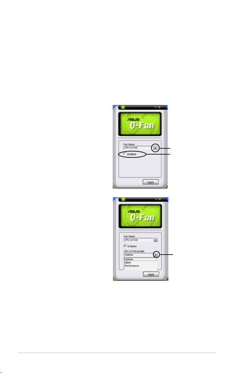
5.3.7 ASUS Q-Fan 2
This ASUS Q-Fan 2 Control feature allows you to set the appropriate performance
level of the CPU Q-Fan 2 or the Chassis Q-Fan 2 for more efcient system
operation. After enabling the Q-Fan 2 function, the fans can be set to automatically
adjust depending on the temperature, to decrease fan speed, or to achieve the
maximum fan speed.
After installing AI Suite from the bundled support DVD, you can launch the utility by
®
double-clicking the AI Suite icon on the Windows
OS taskbar and click the Q-Fan
2 button on the AI Suite main window.
Click the drop-down menu button
and display the fan names. Select
CPU Q-Fan 2 or CHASSIS Q-Fan 2.
Click the box of Enabled to activate
this function.
drop-down list button
Enabled box
Prole list appears after clicking
the Enabled box. Click the drop-
down list button and select a prole.
Optimal mode makes the fans
adjust speed with the temperature;
Silent mode minimizes fan
speed for quiet fan operation;
Performance mode boosts the fan
to achieve maximal fan speed for
click to display the
drop-down list and
the best cooling effect.
select a Q-Fan 2 mode
Click Apply at the bottom to save the setup.
5-22 Chapter 5: Software support
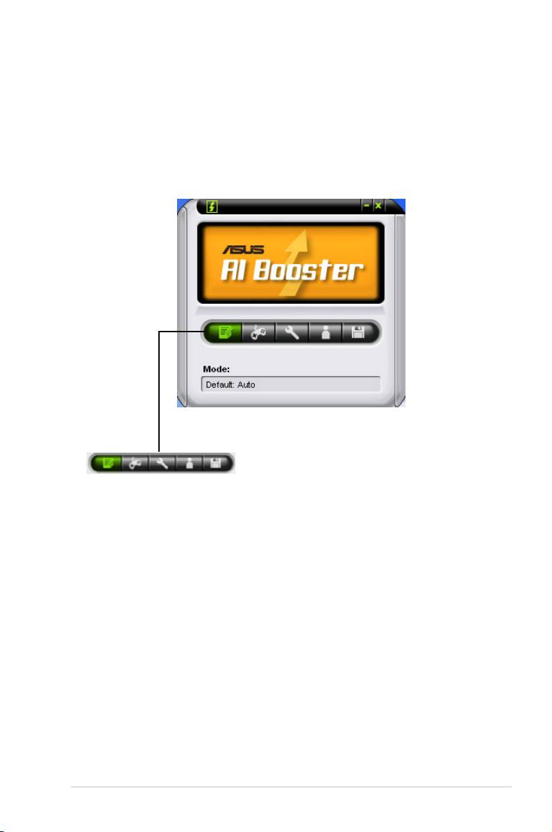
5.3.8 ASUS AI Booster
The ASUS AI Booster application allows you to overclock the CPU speed in
®
WIndows
environment without the hassle of booting the BIOS.
After installing AI Suite from the bundled support DVD, you can launch the utility
®
by double-clicking the AI Suite icon on the Windows
OS taskbar and click the AI
Booster button on the AI Suite main window.
The options on the taskbar allow you to use the default settings, adjust CPU/
Memory/PCI-E frequency manually, or create and apply your personal overclocking
congurations.
ASUS P5E3 Premium/WiFi-AP @n 5-23
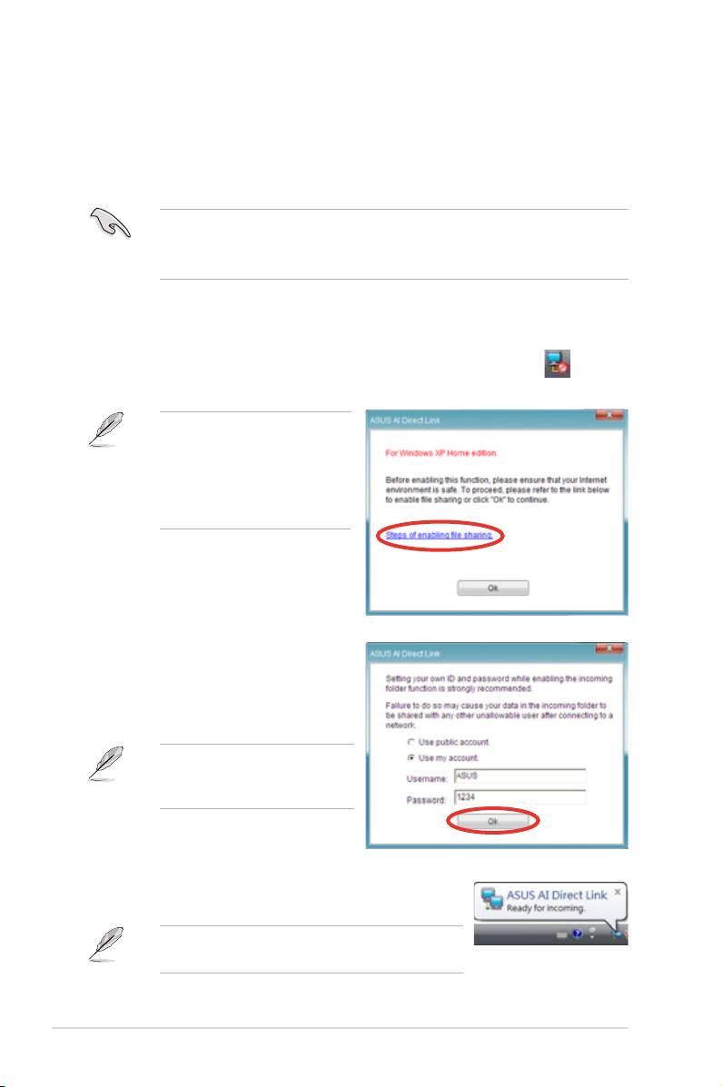
5.3.9 ASUS AI Direct Link
ASUS AI Direct Link allows you to form a computer-to-computer network via a
network cable to share les with high transfer rate. You must rst connect two
computers (at least one of them is ASUS product) using a network cable, and then
install the utility to both computers to avail the AI Direct Link feature.
• Turn off your rewall software other than Windows Firewall before
launching AI Direct Link.
• The transfer rate is limited if you use a 10/100 LAN card.
Using AI Direct Link
To enable the incoming folder:
®
1. From the Windows
taskbar, right click on the AI Direct Link icon and
select Incoming folder > Enable incoming folder.
For Windows XP Home
edition users, click Steps of
enabling le sharing on this
pop-up message and follow
the instructions to enable the
incoming folder.
2. If you want to to verify the incoming
user, select Use my account and
set your username and password.
Otherwise, select Use public
account.
For security’s sake, it is
recommended that you set a
username and password.
3. Click OK and the “Ready for incoming” message
appears.
To disable the incoming folder, select Incoming
folder > Disable incoming folder.
5-24 Chapter 5: Software support
4. Right click on the AI Direct Link
icon and select Incoming folder
> Open incoming folder. The
AIDirectLinkIncoming folder
opens. Put the les you want
to share into this folder. The
authorized user has full access to
this folder.
The default path of the AIDirectLinkIncoming folder is C:\Program Files\ASUS\AI
Direct Link. To change its location, disable the incoming folder rst. Then, select
Incoming folder > Change incoming folder to open the system directories,
and move the AIDirectLinkIncoming folder under another directory.
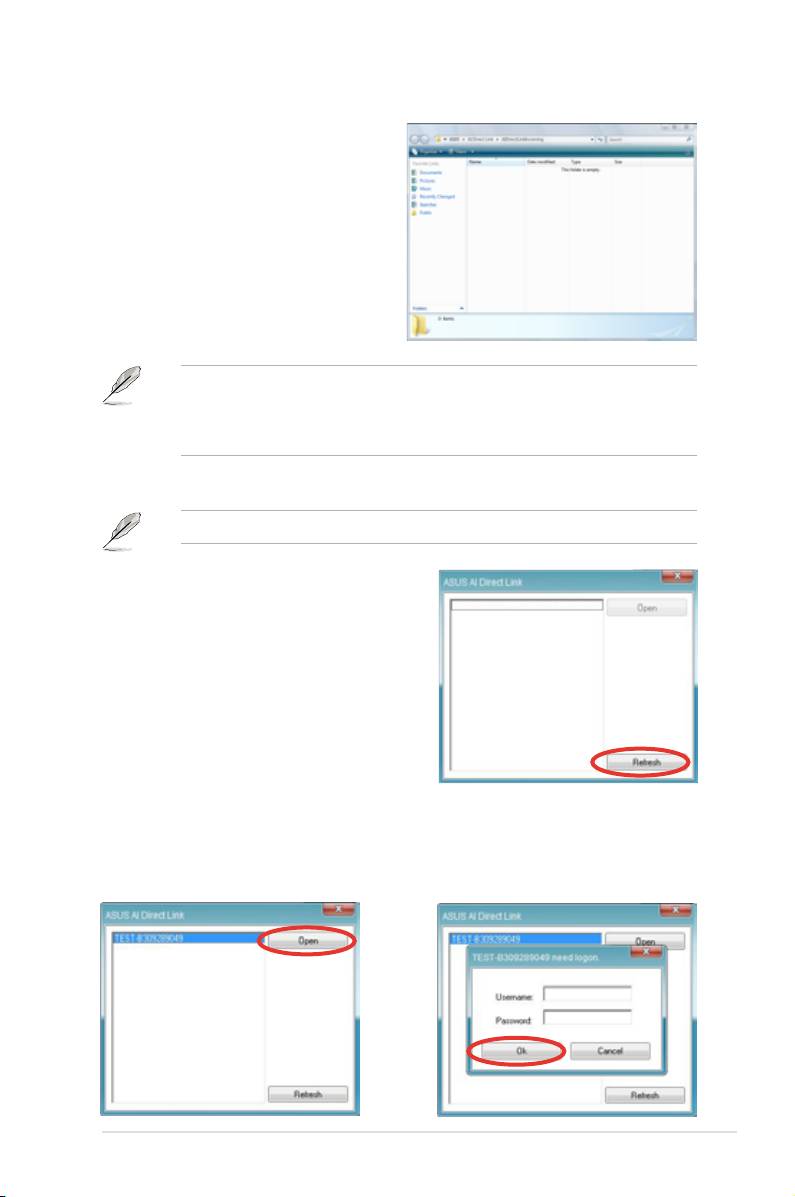
To connect to another computer:
This function is valid for ASUS products only.
®
1. From the Windows
taskbar, right
click on the AI Direct Link icon and
select Connect. The following screen
displays.
2. Click
Refresh. The software starts
searching for the connected computer.
3. The name of the computer found
4. If necessary, enter the authorized
is listed. Click Open to open its
username and password. Click OK
shared folder.
to log in and have full access to
this shared folder.
ASUS P5E3 Premium/WiFi-AP @n 5-25

®
5.3.10 AI Audio 2 (SoundMAX
High Denition Audio utility)
The ADI AD1988B High Denition Audio CODEC provides 8-channel audio
®
capability through the SoundMAX
audio utility with AudioESP™ software to
deliver the ultimate audio experience on your PC. The software implements high
quality audio synthesis/rendering, 3D sound positioning, and advanced voice-input
technologies.
Follow the installation wizard to install the ADI AD1988B Audio Driver from the
®
support DVD that came with the motherboard package to activate the SoundMAX
audio utility.
You must use 4-channel, 6-channel or 8-channel speakers for this setup.
®
If the SoundMAX
audio utility is correctly installed, you
®
®
will nd the SoundMAX
/ SoundMAX
BlackHawk icon
on the taskbar.
5-26 Chapter 5: Software support
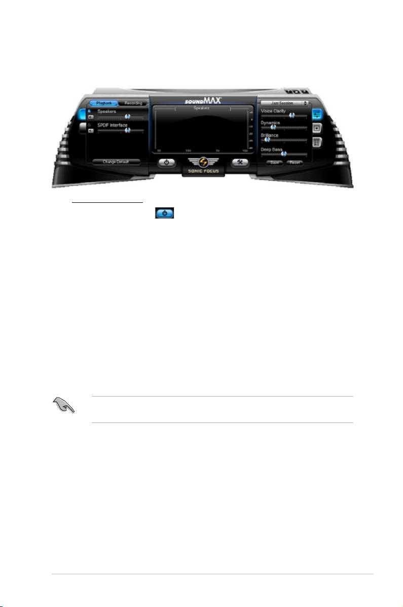
A. SoundMAX BlackHawk (AI Audio 2)
®
If you are using Windows
Vista operation system, from the taskbar, double-click
®
®
the SoundMAX
BlackHawk icon to display the SoundMAX
control panel.
Enabling AI Audio 2
Click the power button to activate digital signal processing.
AI Audio 2, with the new SoundMAX BlackHawk by Sonic Focus, brings you
more multi-media enjoyment.
Fidelity Compensation
After you click the power button, the utility would compensate for the delity
lost in the compression process and make the audio output quasi-original
when reverting the compressed audio streams back to the uncompressed
condition.
Sound Field Expansion
AI Audio 2 also expands the stereophonic sound eld to a multi-channel
one with realistic front and rear environment.
Surround Virtualization
Activating this function virtualizes surround sound with the vocal clarity
added for use with stereo speakers or headphones.
®
SoundMAX BlackHawk (AI Audio 2) is only available under the Windows
Vista™ operating system.
ASUS P5E3 Premium/WiFi-AP @n 5-27
Playback Settings
To congure the playback settings, click the
Playback
button on the control
panel. You can adjust the volume of the
Speakers
and
SPDIF
Interface
or
mute the audio.
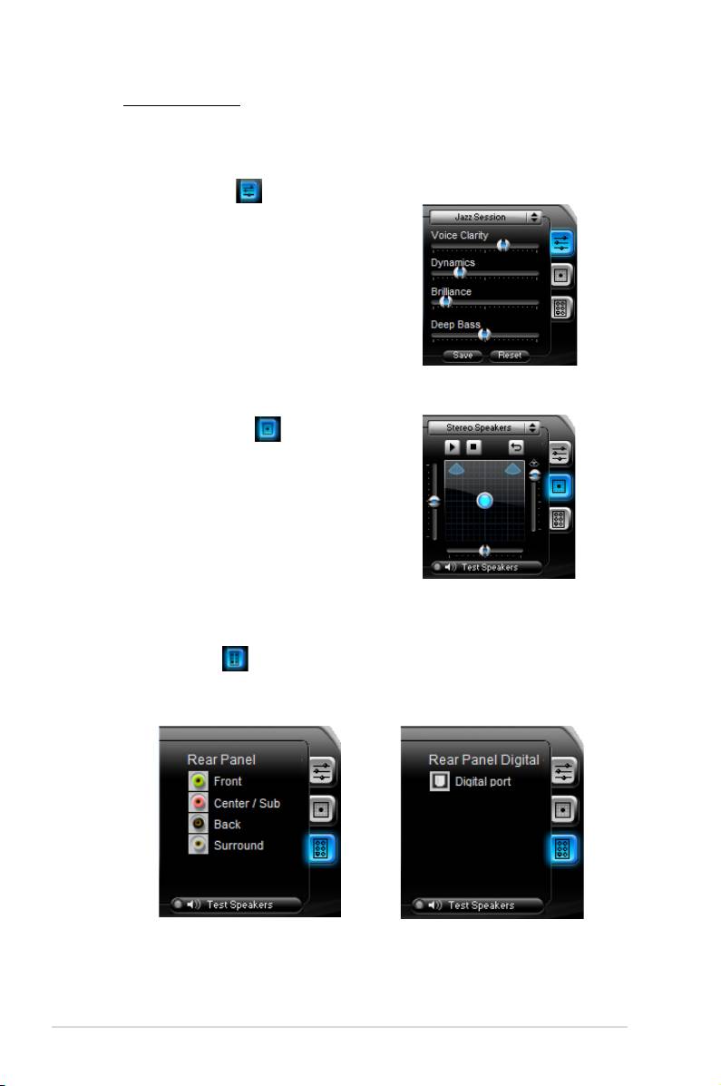
Preset settings
Click and expand the drop-down menu
to select your preferred Digital Signal
Processing (DSP) preset. Move the
sliders to customize the values of
Voice Clarity
,
Dynamics
,
Brilliance
,
and
Deep Bass
of each preset.
Click
Save
to save the changes to
the current preset. Or, click
Reset
to
discard the changes and restore the
preset to the factory defaults.
Surround settings
Allows you to change the settings
of the stereo speakers. Move the
sliders to change the listener position
or adjust the center channel volume.
Press the
Test Speakers
button to
perform speaker test.
Port settings
Click this port settings tab to display the rear panel ports conguration for
the speakers or rear panel digital port conguration for the SPDIF interface.
5-28 Chapter 5: Software support
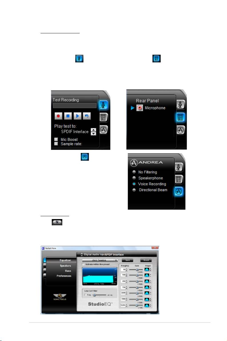
Recording Settings
To change the recording
settings, click the
Recording
button on the control
panel. You can adjust the speaker delay of
Microphone
or
Line In
by moving
the slider rightward or leftward.
Record testing
Port settings
Click the tab to perform test
Click the tab to display the rear
recording and play the test sample
panel ports for Microphone or
through the speakers or the SPDIF
Line In.
interface.
ANDREA settings
Allows you to select an
enhanced microphone input
features, including
No Filtering
,
Speakerphone
, V
oice Recording
,
and
Directional Beam
.
More Settings
Click for the further congurations.
Equalizer
Allows you to congure and customize all the DSP presets frequencies.
ASUS P5E3 Premium/WiFi-AP @n 5-29
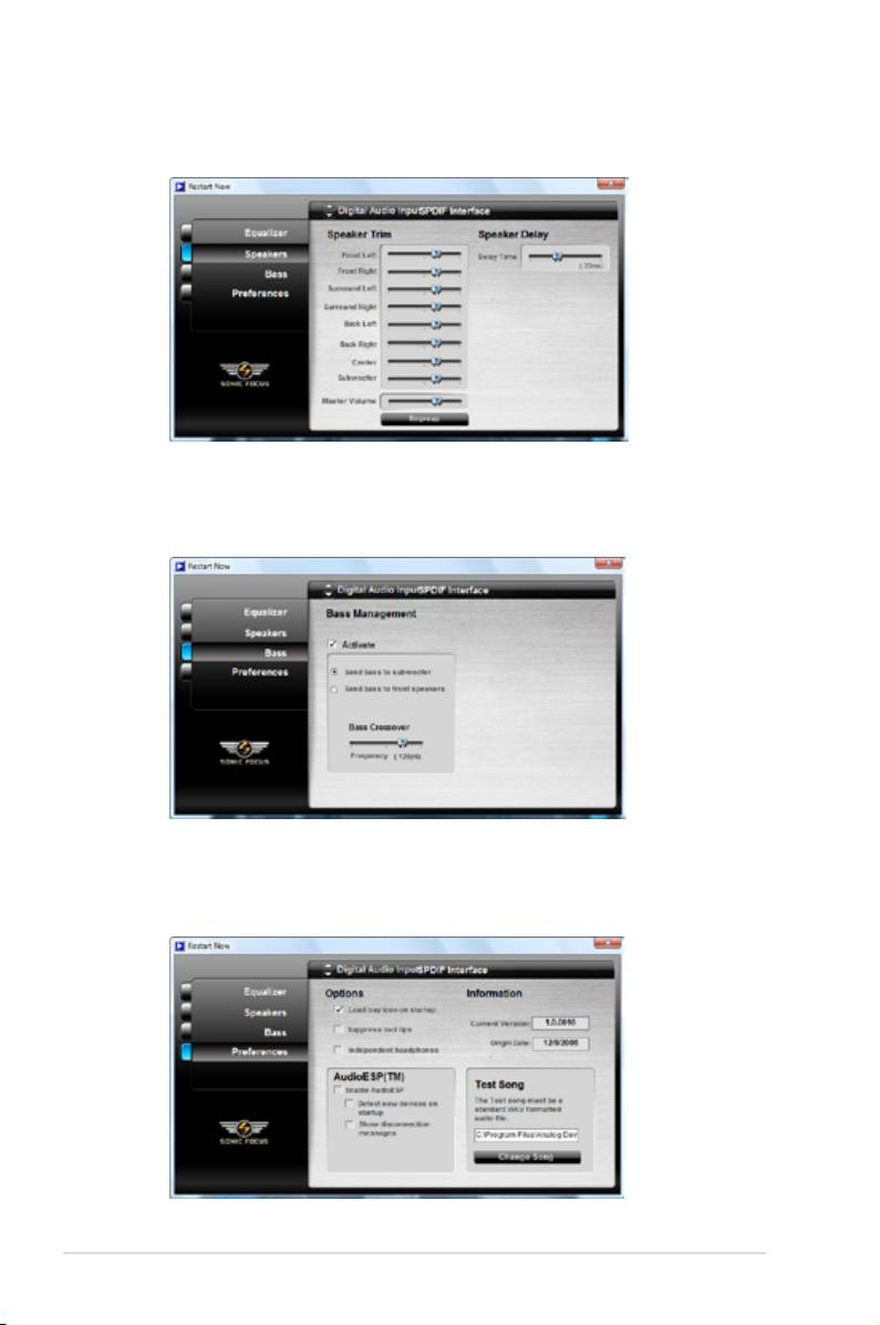
Speakers
Allows you to adjust the
Speaker Trim
and
Speaker Delay
.
Bass
Allows you to do the Bass management.
Preferences
Displays the preference options for this utility, version information,
AudioESP, etc.
5-30 Chapter 5: Software support
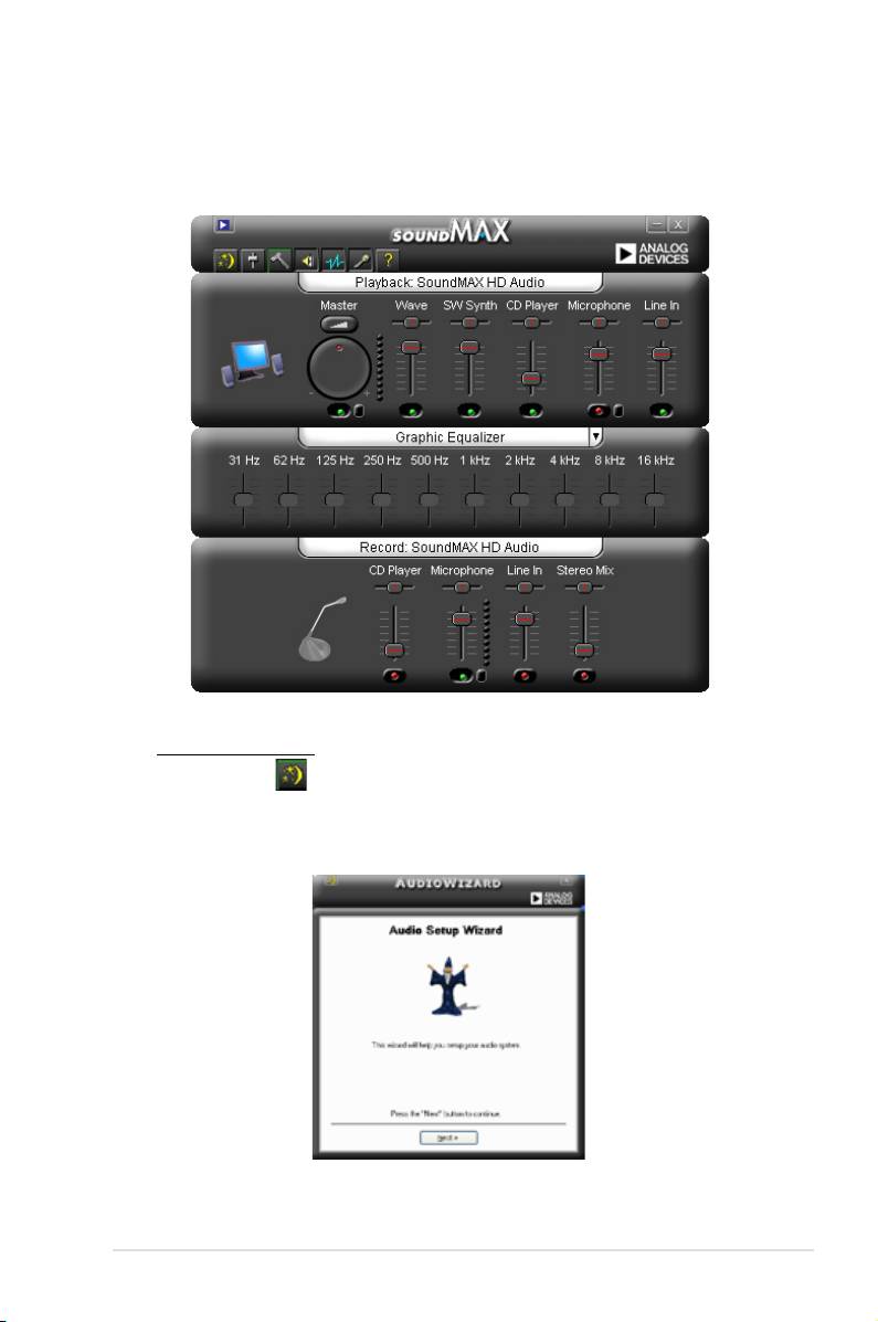
B. SoundMAX
®
If you are using Windows
XP operating system,from the taskbar, double-click on
®
®
the SoundMAX
icon to display the SoundMAX
Control Panel.
Audio Setup Wizard
®
By clicking the icon from the SoundMAX
control panel, you can easily
congure your audio settings. Simply follow succeeding screen instructions
and begin enjoying High Denition Audio.
ASUS P5E3 Premium/WiFi-AP @n 5-31
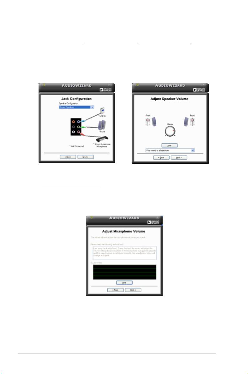
Jack configuration
Adjust speaker volume
This screen helps you congure
This screen helps you adjust
your computer’s audio ports,
speaker volume. Click the
Test
depending on the audio devices
button to hear the changes you
you have installed.
have made.
Adjust microphone volume
This screen helps you adjust microphone volume. You will be asked to read
pre-written text to allow the AudioWizard to adjust the volume as you speak.
5-32 Chapter 5: Software support
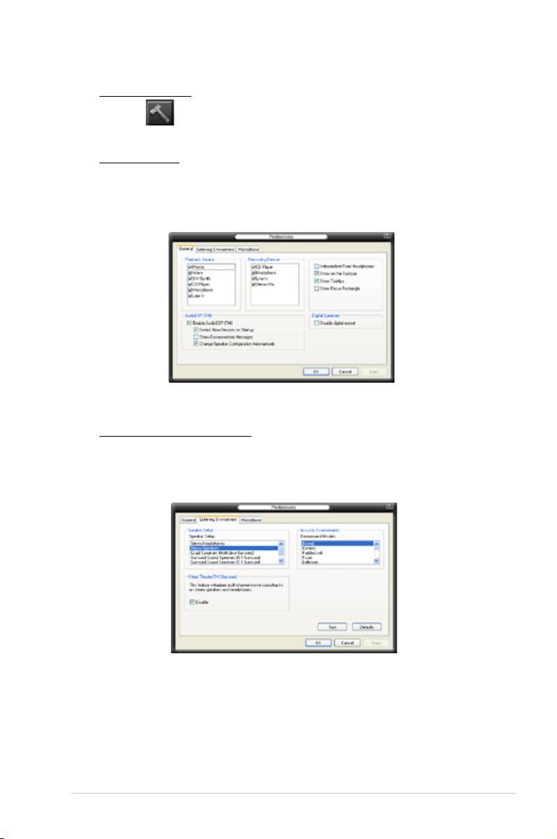
Audio preferences
Click the icon to go to the Preferences page. This page allows you to
change various audio settings.
General options
Click the General tab to choose your playback and recording devices, enable/
disable the AudioESP™ feature, and enable/disable digital output.
Listening Environment options
Click the Listening Environment tab to set up your speaker, acoustic
environment, and enable/disable the Virtual Theater Surround function.
ASUS P5E3 Premium/WiFi-AP @n 5-33
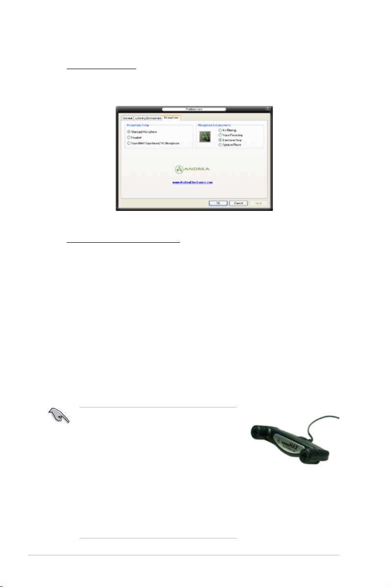
Microphone options
Click the Microphone tab to optimize your microphone input settings.
Enhanced Microphone Features
Voice recording
Enables Noise Filter function. Detects repetitive and stationary noises
like computer fans, air conditioners, and other background noises then
eliminates it in the incoming audio stream while recording. You can enable
it for a better recording quality.
Directional Array
Receives only the sound coming from the reception cone and eliminates
interferences including neighboring speakers and reverberations. You can
enable it to transit clearer sound during on-line games, MSN, or Skype.
Speaker Phone
Advanced de-reverberation techniques can help to reduce echo and
minimize its effect on the speech engine. You can enable it when you have
conference call to reduce echoes in the other side.
• The Directional Array and Speaker
Phonefunction only when working with the
ASUS Array Mic.
• The ASUS Array Mic is purchased
separately.
• If you are using Windows Vista, you have to
manually enable the directional Array and
Speaker Phone function. Go to
Control
panel
>
Sound
. Click the
Recording
tab on
the top and select
Microphone
. Click the
Microphone Enhancement
tab and check
Array Mic
.
5-34 Chapter 5: Software support

5.3.11 ASUS Express Gate
ASUS Express Gate is an instant-on environment that gives you quick access to
web and Skype. Within a few seconds of powering on your computer, you will be
at the Express Gate menu where you can start the web browser, Skype, or other
Express Gate applications.
Express Gate is entirely self-contained on the motherboard, so you can use it at
any time, even without a hard drive attached!
The First Screen
Express Gate’s rst screen appears within a few seconds after you power on. From
here, you can immediately start the web browser or Skype.
You can also choose to continue booting normally (e.g. to your installed OS such
as Windows), enter BIOS setup, or power off.
If you don’t make any selection, Express Gate will automatically exit and boot
to your normal OS after a certain amount of time, which can be adjusted in the
BIOS. Refer to page 5-40 for more details. The timer countdown is shown on-
screen inside the “boot to OS” button. As you move the mouse or type a key, the
countdown stops and the timer disappears, so you can take your time to make a
selection.
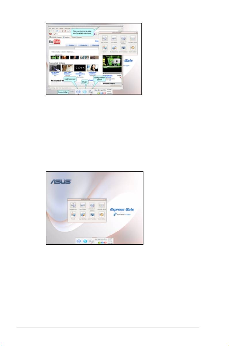
The Express Gate Environment
The very rst time you enter the Express Gate environment (by launching either
web or Skype from the rst screen), a rst time wizard will guide you through basic
Express Gate congurations. Basic congurations include language, date and time
and screen resolution.
Once inside the Express Gate environment, click on the icons on the LaunchBar,
by default at bottom of the screen, to launch or switch between applications. You
can re-arrange, re-size and move windows. Bring a window to the foreground by
clicking within it or by clicking on its corresponding application icon. Re-size a
window by dragging any of its four corners. Move a window by dragging its title bar.
ASUS P5E3 Premium/WiFi-AP @n 5-35
Besides using the LaunchBar, you can also switch between applications by
pressing <Alt> +<Tab> on the keyboard. You can also right-click anywhere on the
desktop to bring up a menu of applications.
The red triangle on an application icon in the LaunchBar denotes that the
application is already running. This means that you can switch to it without any
delay. In the rare case where an application stops responding, right-click on its icon
to force close it.
Conguration Panel
Use the conguration panel to change various Express Gate settings.
Click on an icon to open a particular conguration tool. The following tools are
available:
Date and Time
: set current date and time as well as time zone.
Input Method
: choose your preferred input language and method.
Language and Keyboard
: choose your language and keyboard preferences.
LaunchBar Setting
: customize your LaunchBar (where it docks, whether it auto-
hides, etc.)
5-36 Chapter 5: Software support
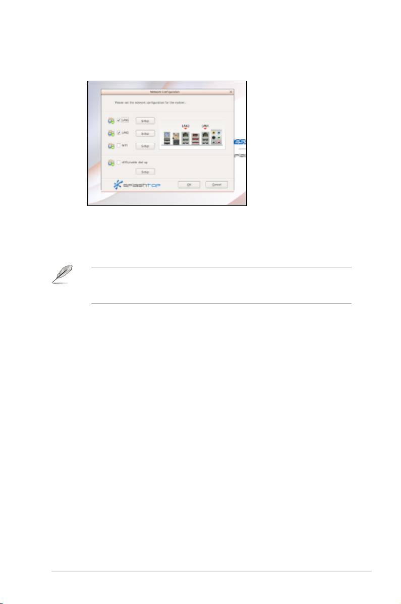
Network Conguration
Specify how your computer connects to the Internet. Enable all the network ports
that you may use (LAN1, LAN2, and/or wireless [optional]). LAN1 and LAN2 refer
to the two RJ-45 network ports on your computer.
• You can connect the LAN cable to either port, and Express Gate will
automatically use the connected port.
• The back I/O differs depending on the motherboard.
Also specify whether each port uses DHCP (most common) or static IP. For PPPoE
and wireless (optional), set the login credentials (user name, password, SSID, etc.)
as well.
Reset Express Gate
Clear Express Gate’s settings as well as any personal information stored by the
web browser (bookmarks, cookies, browsing history, etc.). This is also useful in the
rare case where settings become corrupted.
The rst time wizard will run again when you enter the Express Gate
environment after clearing its settings.
Screen Resolution
Choose the most optimal screen resolution for your display.
Volume Control
Control the volume for your speaker output, microphone input, etc.
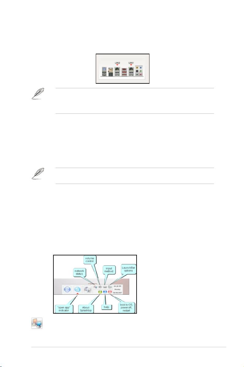
LaunchBar
The LaunchBar has several system icons that show you various system statuses
and let you congure individual Express Gate settings. The LaunchBar can be
congured to auto-hide, if you want more screen space for the applications. It can
also be congured to dock on any of the four sides of the screen.
shows network status; click to congure network
ASUS P5E3 Premium/WiFi-AP @n 5-37
shows mute status; click to change volume
click to choose input language and method as well as keyboard shortcuts
(Ctrl-Space by default)
click to change LaunchBar options (auto-hide, docking position, etc)
left-click to set date and time; right-click to choose between 12-hour and
24-hour display formats
click to show ”About Express Gate”
click to open Express Gate Help
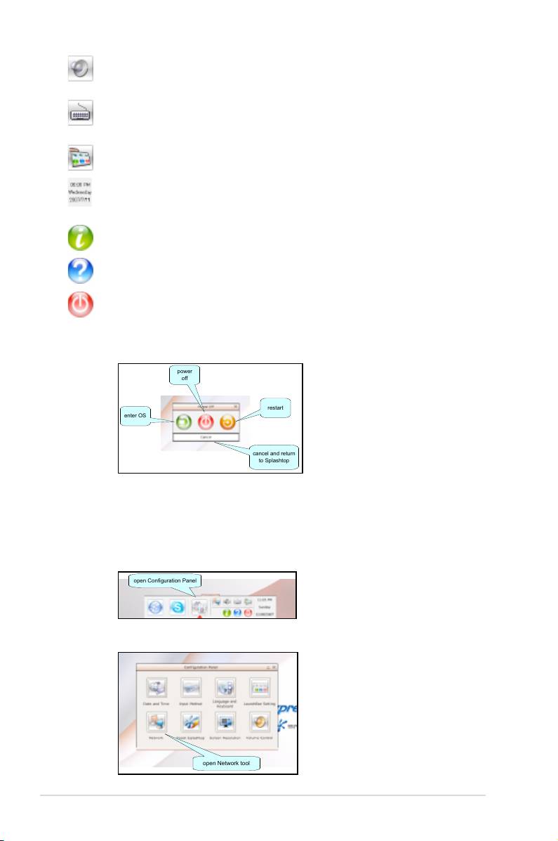
click to bring up power options window to boot to OS, restart or power
down
This window is also shown when you press Ctrl-Alt-Del on the keyboard.
5-38 Chapter 5: Software support
power
off
restart
enter OS
cancel and return
to Splashtop
How Do I Get on to the Internet
If Internet doesn’t seem to be working in the Express Gate environment, check the
following:
1. Open the Conguration Panel.
open Configuration Panel
2. Open Network tool.
open Network tool
3. Make the proper network congurations.
Each network interface is enabled immediately when you check the box next
to it.
• If you use a network cable connected to a home router (which is then
connected to your DSL/cable modem), enable both LAN1 and LAN2.
Express Gate will automatically use whichever port (LAN1 or LAN2) is
connected.
If you plug the network cable into a different port while Express Gate is running
(e.g. move the cable from LAN1 to LAN2), you may need to restart Express
Gate for it to detect the change.
• The most common scenario is for your computer to automatically obtain
network settings (i.e. DHCP). If this is the case, you don’t need to go into
“Setup” for either LAN1 or LAN2. If this is not the case, enter “Setup”
to congure the static IP settings manually.
• If you use wireless, go into “Setup” for the WiFi option. Under the WiFi
tab, enter the SSID (name of your wireless access point). If your wireless
access point has security enabled, select the security algorithm from the
pulldown menu (e.g. WEPAUTO) and enter the password.
Then enable WiFi to establish the wireless connection.
• If you use a network cable connected directly to your DSL/cable modem
(no router in between), go into “Setup” for xDSL/cable dial-up. This
method is also referred to as PPPoE. Choose whether the DSL/cable
modem is connected to your computer’s LAN1 or LAN2 port. (Refer to
the drawing in the Network tool to gure out which is LAN1 or LAN2.)
Then enter the username and password for your dial-up account.
Then enable xDSL/cable dial-up to establish the PPPoE connection.
When PPPoE is enabled, the port (LAN1 or LAN2) it uses will
automatically be unchecked and grayed out.
ASUS P5E3 Premium/WiFi-AP @n 5-39

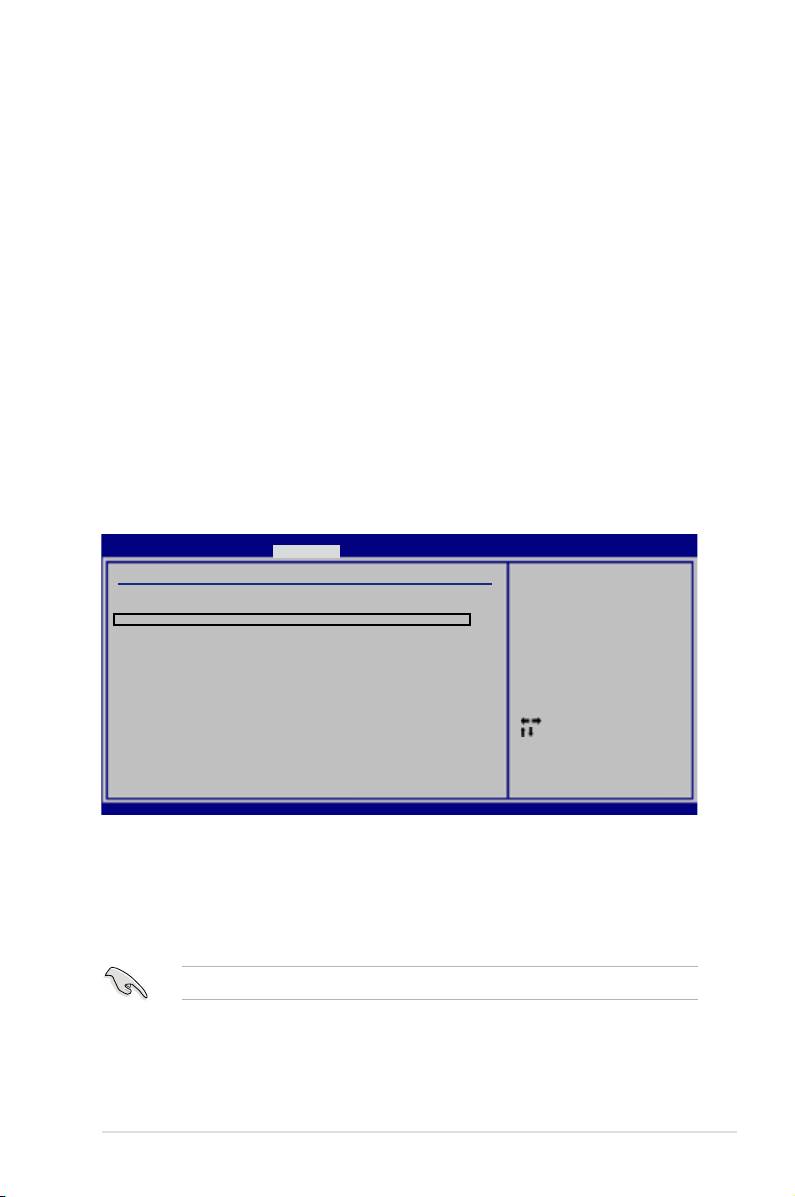
Conguring Express Gate in BIOS Setup
Enter BIOS setup by pressing DEL key after powering on or by clicking on the
BIOS setup icon on Express Gate’s rst screen. Express Gate conguration
options are under Tools conguration menu page.
BIOS SETUP UTILITY
Main Ai Tweaker Advanced Power Boot Tools Exit
ASUS EZ Flash 2
Press ENTER to run
ASUS Express Gate [Enabled]
the utility to select
Reset User Data [No]
and update BIOS.
Timeout [10]
This utility doesn't
support :
ASUS O.C. Prole
1.NTFS format
Ai Net 2
Express Gate [Enabled]
Allows you to enable or disable the Express Gate feature. Set this item to [Enabled]
to activate the Express Gate feature. Conguration options: [Disabled] [Enabled]
Reset User Data [No]
Allows you to clear Express Gate’s user data.
Conguration options: [No] [Reset]
When setting this item to [Reset], make sure to save the setting to the BIOS
so that the user data will be cleared the next time you enter the Express
Gate. User data includes the Express Gate’s settings as well as any personal
information stored by the web browser (bookmarks, cookies, browsing
history, etc.). This is useful in the rare case where corrupt settings prevent the
Express Gate environment from launching properly.
The rst time wizard will run again when you enter the Express Gate
environment after clearing its settings.
Timeout [10]
Sets the amount of time the system waits at the Express Gate’s rst screen
before defaulting to starting Windows or other installed OS. Choosing [Choose]
means waiting indenitely at the rst screen for user action.
Conguration options: [1 second] ~ [30 seconds]
The time length is adjusted by typing the desired values using the numeric
keypad and press the <Enter> key.
Express Gate Updater
Use the Express Gate Updater to update your existing Express Gate software to
new versions or to restore the Express Gate software if it is ever corrupted. You
can nd
Express Gate Updater Installer
on the support DVD or download it from
the ASUS support website. It runs on Windows.
New versions of the Express Gate software will be released regularly, adding
renements or new applications. You can nd original version of the software
on the support DVD or download new versions from the ASUS support website.
Express Gate software is released as an image le with .DFI extension.
5-40 Chapter 5: Software support
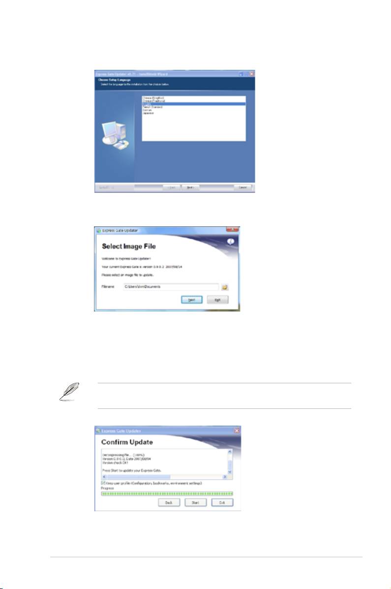
To install the Express Gate Updater, launch the installer and follow on-screen
prompts.
To use the Express Gate Updater, launch the application and follow on-screen
prompts.
The Updater can preserve your Express Gate settings and personal data (web
browser bookmarks, etc.) while doing an update. Use the checkbox “Keep user
prole” to decide whether the Updater should do so.
Clearing the user data is useful in the rare case where corrupt settings prevent the
Express Gate environment from launching properly.
The rst time wizard will run again when you enter the Express Gate
environment after clearing its settings.
ASUS P5E3 Premium/WiFi-AP @n 5-41

5.4 RAID congurations
The motherboard comes with two RAID controllers that allow you to congure
Serial ATA hard disk drives as RAID sets.
®
• The
Intel
ICH9R Southbridge
RAID
includes a high performance SATA
RAID controller that supports RAID 0, RAID 1, RAID 10, and RAID 5 for six
independent Serial ATA channels.
®
• The
JMicro
JMB363 RAID
includes a high performance SATA RAID controller
that supports RAID 0, 1, and JBOD for two independent Serial ATA channels.
5.4.1 RAID denitions
RAID 0
(Data striping)
optimizes two identical hard disk drives to read and write
data in parallel, interleaved stacks. Two hard disks perform the same work as a
single drive but at a sustained data transfer rate, double that of a single disk alone,
thus improving data access and storage. Use of two new identical hard disk drives
is required for this setup.
RAID 1
(Data mirroring)
copies and maintains an identical image of data from
one drive to a second drive. If one drive fails, the disk array management software
directs all applications to the surviving drive as it contains a complete copy of
the data in the other drive. This RAID conguration provides data protection and
increases fault tolerance to the entire system. Use two new drives or use an
existing drive and a new drive for this setup. The new drive must be of the same
size or larger than the existing drive.
RAID 5
stripes both data and parity information across three or more hard
disk drives. Among the advantages of RAID 5 conguration include better
HDD performance, fault tolerance, and higher storage capacity. The RAID
5 conguration is best suited for transaction processing, relational database
applications, enterprise resource planning, and other business systems. Use a
minimum of three identical hard disk drives for this setup.
RAID 10
is data striping and data mirroring combined without parity (redundancy
data) having to be calculated and written. With the RAID 10* conguration you get
all the benets of both RAID 0 and RAID 1 congurations. Use four new hard disk
drives or use an existing drive and three new drives for this setup.
JBOD
(Spanning)
stands for Just a Bunch of Disks and refers to hard disk drives
that are not yet congured as a RAID set. This conguration stores the same data
redundantly on multiple disks that appear as a single disk on the operating system.
Spanning does not deliver any advantage over using separate disks independently
and does not provide fault tolerance or other RAID performance benets.
®
Intel
Matrix Storage.
The Intel® Matrix Storage technology supported by the
ICH9R chip allows you to create a RAID 0, RAID 1, RAID 5, and RAID 10* function
to improve both system performance and data safety. You can also combine two
RAID sets to get higher performance, capacity, or fault tolerance provided by the
difference RAID function. For example, RAID 0 and RAID 1 set can be created by
using only two identical hard disk drives.
5-42 Chapter 5: Software support

5.4.2 Installing Serial ATA hard disks
The motherboard supports Serial ATA hard disk drives. For optimal performance,
install identical drives of the same model and capacity when creating a disk array.
To install the SATA hard disks for a RAID conguration:
1. Install the SATA hard disks into the drive bays.
2. Connect the SATA signal cables.
3. Connect a SATA power cable to the power connector on each drive.
®
5.4.3 Intel
RAID congurations
®
This motherboard supports RAID 0, RAID 1, RAID 5, RAID 10 (0+1) and Intel
®
Matrix Storage congurations for Serial ATA hard disks drives through the Intel
ICH9R Southbridge chip.
Setting the RAID item in BIOS
You must set the RAID item in the BIOS Setup before you can create a RAID
set(s). To do this:
1. Enter the BIOS Setup during POST.
2. Go to the
Main
menu, select
SATA Conguration
, then press <Enter>.
3. Select the
Congure SATA as
item, then press <Enter> to display the
conguration options.
4. Select
RAID
from the conguration options, then press <Enter>.
5. Save your changes, then exit the BIOS Setup.
Refer to the system or the motherboard user guide for details on entering and
navigating through the BIOS Setup.
ASUS P5E3 Premium/WiFi-AP @n 5-43

®
Intel
Matrix Storage Manager Option ROM Utility
®
The Intel
Matrix Storage Manager Option ROM utility allows you to create RAID 0,
RAID 1, RAID 10 (RAID 0+1), and RAID 5 set(s) from Serial ATA hard disk drives
that are connected to the Serial ATA connectors supported by the Southbridge.
®
To enter the Intel
Application Accelerator RAID Option ROM utility:
1. Install all the Serial ATA hard disk drives.
2. Turn on the system.
3. During POST, press <Ctrl+I> to display the utility main menu.
Intel(R) Matrix Storage Manager Option ROM v5.0.0.1032 ICH9R wRAID5
Copyright(C) 2003-05 Intel Corporation. All Rights Reserved.
[ MAIN MENU ]
1. Create RAID Volume
2. Delete RAID Volume
3. Reset Disks to Non-RAID
4. Exit
[ DISK/VOLUME INFORMATION ]
RAID Volumes:
None dened.
Physical Disks:
Port Drive Model Serial # Size Type/Status(Vol ID)
0 XXXXXXXXXXX XXXXXXXX XX.XXGB
Non-RAID Disk
1 XXXXXXXXXXX XXXXXXXX XX.XXGB
Non-RAID Disk
2 XXXXXXXXXXX XXXXXXXX XX.XXGB
Non-RAID Disk
3 XXXXXXXXXXX XXXXXXXX XX.XXGB
Non-RAID Disk
[↑↓]-Select [ESC]-Exit [ENTER]-Select Menu
The navigation keys at the bottom of the screen allow you to move through
the menus and select the menu options.
The RAID BIOS setup screens shown in this section are for reference only and
may not exactly match the items on your screen.
5-44 Chapter 5: Software support

Creating a RAID 0 set (striped)
To create a RAID 0 set:
1. From the utility main menu, select 1. Create RAID Volume, then press
<Enter>. This screen appears.
Intel(R) Matrix Storage Manager Option ROM v5.0.0.1032 ICH9R wRAID5
Copyright(C) 2003-05 Intel Corporation. All Rights Reserved.
[ CREATE ARRAY MENU ]
Name:
Volume0
RAID Level:
RAID0(Stripe)
Disks:
Select Disks
Strip Size:
128KB
Capacity:
0.0 GB
Create Volume
[ DISK/VOLUME INFORMATION ]
Enter a string between 1 and 16 characters in length that can be used
to uniquely identify the RAID volume. This name is case sensitive and
cannot contain special characters.
[↑↓]-Change [TAB]-Next [ESC]-Previous Menu [Enter]-Select
2. Enter a name for the RAID 0 set, then press <Enter>.
3. When the RAID Level item is highlighted, press the up/down arrow key to
select RAID 0(Stripe), then press <Enter>.
4. When the Disks item is highlighted, press <Enter> to select the hard disk
drives to congure as RAID. This pop-up screen appears.
[ SELECT DISKS ]
Port Drive Model Serial # Size Status
0 XXXXXXXXXXXX XXXXXXXX XX.XGB Non-RAID Disk
1 XXXXXXXXXXXX XXXXXXXX XX.XGB Non-RAID Disk
2 XXXXXXXXXXXX XXXXXXXX XX.XGB Non-RAID Disk
3 XXXXXXXXXXXX XXXXXXXX XX.XGB Non-RAID Disk
Select 2 to 4 disks to use in creating the volume.
[↑↓]-Previous/Next [SPACE]-Selects [ENTER]-Selection Complete
5. Use the up/down arrow key to highlight a drive, then press <Space> to
select. A small triangle marks the selected drive. Press <Enter> after
completing your selection.
ASUS P5E3 Premium/WiFi-AP @n 5-45

6. Use the up/down arrow key to select the stripe size for the RAID 0 array, then
press <Enter>. The available stripe size values range from 4 KB to 128 KB.
The default stripe size is 128 KB.
We recommend a lower stripe size for server systems, and a higher stripe size
for multimedia computer systems used mainly for audio and video editing.
7. Key in the RAID volume capacity that you want, then press <Enter>. The
default value indicates the maximum allowed capacity.
8. Press <Enter> when the Create Volume item is highlighted. This warning
message appears.
WARNING: ALL DATA ON SELECTED DISKS WILL BE LOST.
Are you sure you want to create this volume? (Y/N):
9. Press <Y> to create the RAID volume and return to the main menu, or <N> to
go back to the Create Volume menu.
5-46 Chapter 5: Software support

Creating a RAID 1 set (mirrored)
To create a RAID 1 set:
1. From the utility main menu, select 1. Create RAID Volume, then press
<Enter>. This screen appears.
Intel(R) Matrix Storage Manager Option ROM v5.0.0.1032 ICH9R wRAID5
Copyright(C) 2003-05 Intel Corporation. All Rights Reserved.
[ CREATE ARRAY MENU ]
Name:
Volume1
RAID Level:
RAID1(Mirror)
Disks:
Select Disks
Strip Size:
N/A
Capacity:
XX.X GB
Create Volume
[ DISK/VOLUME INFORMATION ]
Enter a string between 1 and 16 characters in length that can be used
to uniquely identify the RAID volume. This name is case sensitive and
cannot contain special characters.
[↑↓]-Change [TAB]-Next [ESC]-Previous Menu [Enter]-Select
2. Enter a name for the RAID 1 set, then press <Enter>.
3. When the RAID Level item is highlighted, press the up/down arrow key to
select RAID 1(Mirror), then press <Enter>.
4. When the Capacity item is highlighted, key in the RAID volume capacity that
you want, then press <Enter>. The default value indicates the maximum
allowed capacity.
5. Press <Enter> when the Create Volume item is highlighted. This warning
message appears.
WARNING: ALL DATA ON SELECTED DISKS WILL BE LOST.
Are you sure you want to create this volume? (Y/N):
6. Press <Y> to create the RAID volume and return to main menu or <N> to go
back to Create Volume menu.
ASUS P5E3 Premium/WiFi-AP @n 5-47

Creating a RAID 10 set (RAID 0+1)
To create a RAID 10 set:
1. From the utility main menu, select 1. Create RAID Volume, then press
<Enter>. This screen appears.
Intel(R) Matrix Storage Manager Option ROM v5.0.0.1032 ICH9R wRAID5
Copyright(C) 2003-05 Intel Corporation. All Rights Reserved.
[ CREATE ARRAY MENU ]
Name:
Volume10
RAID Level:
RAID10(RAID0+1)
Disks:
Select Disks
Strip Size:
128KB
Capacity:
XXX.X GB
Create Volume
[ DISK/VOLUME INFORMATION ]
Enter a string between 1 and 16 characters in length that can be used
to uniquely identify the RAID volume. This name is case sensitive and
cannot contain special characters.
[↑↓]-Change [TAB]-Next [ESC]-Previous Menu [Enter]-Select
2. Enter a name for the RAID 10 set, then press <Enter>.
3. When the RAID Level item is highlighted, press the up/down arrow key to
select RAID 10(RAID0+1), then press <Enter>.
4. When the Stripe Size item is highlighted, press the up/down arrow key to
select the stripe size for the RAID 10 array, then press <Enter>. The available
stripe size values range from 4 KB to 128 KB. The default stripe size is 64
KB.
We recommend a lower stripe size for server systems, and a higher stripe size
for multimedia computer systems used mainly for audio and video editing.
5. Key in the RAID volume capacity that you want then press <Enter> when
the Capacity item is highlighted. The default value indicates the maximum
allowed capacity.
5-48 Chapter 5: Software support

6. Press <Enter> when the Create Volume item is highlighted. This warning
message appears.
WARNING: ALL DATA ON SELECTED DISKS WILL BE LOST.
Are you sure you want to create this volume? (Y/N):
7. Press <Y> to create the RAID volume and return to the main menu or <N> to
go back to the Create Volume menu.
Creating a RAID 5 set (parity)
To create a RAID 5 set:
1. From the utility main menu, select 1. Create RAID Volume, then press
<Enter>. This screen appears.
Intel(R) Matrix Storage Manager Option ROM v5.0.0.1032 ICH9R wRAID5
Copyright(C) 2003-05 Intel Corporation. All Rights Reserved.
[ CREATE ARRAY MENU ]
Name:
Volume5
RAID Level:
RAID5(Parity)
Disks:
Select Disks
Strip Size:
64KB
Capacity:
0.0 GB
Create Volume
[ DISK/VOLUME INFORMATION ]
Enter a string between 1 and 16 characters in length that can be used
to uniquely identify the RAID volume. This name is case sensitive and
cannot contain special characters.
[↑↓]-Change [TAB]-Next [ESC]-Previous Menu [Enter]-Select
2. Enter a name for the RAID 5 set, then press <Enter>.
3. When the RAID Level item is highlighted, press the up/down arrow key to
select RAID 5(Parity), then press <Enter>.
ASUS P5E3 Premium/WiFi-AP @n 5-49

4. The Disks item is highlighted, press <Enter> to select the hard disk drives to
congure as RAID. The following pop-up screen appears.
[ SELECT DISKS ]
Port Drive Model Serial # Size Status
0 XXXXXXXXXXXX XXXXXXXX XX.XGB Non-RAID Disk
1 XXXXXXXXXXXX XXXXXXXX XX.XGB Non-RAID Disk
2 XXXXXXXXXXXX XXXXXXXX XX.XGB Non-RAID Disk
3 XXXXXXXXXXXX XXXXXXXX XX.XGB Non-RAID Disk
Select 2 to 4 disks to use in creating the volume.
[↑↓]-Previous/Next [SPACE]-Selects [ENTER]-Selection Complete
5. Use the up/down arrow key to highlight the drive you want to set, then press
<Space> to select. A small triangle marks the selected drive. Press <Enter>
after completing your selection.
6. When the Stripe Size item is highlighted, press the up/down arrow key
to select the stripe size for the RAID 5 array, then press <Enter>.
The available stripe size values range from 4 KB to 128 KB. The default stripe
size is 64 KB.
We recommend a lower stripe size for server systems, and a higher stripe size
for multimedia computer systems used mainly for audio and video editing.
7. Key in the RAID volume capacity that you want, then press <Enter> when
the Capacity item is highlighted. The default value indicates the maximum
allowed capacity.
8. Press <Enter> when the Create Volume item is highlighted. This warning
message appears.
WARNING: ALL DATA ON SELECTED DISKS WILL BE LOST.
Are you sure you want to create this volume? (Y/N):
9. Press <Y> to create the RAID volume and return to the main menu or <N> to
go back to the Create Volume menu.
5-50 Chapter 5: Software support
®
5.4.4 JMicron
RAID Conguration
®
The JMicron
Serial ATA controller allows you to congure RAID 0, RAID 1 and
JBOD sets on the external Serial ATA hard disk drives.
Before creating a RAID set
Prepare the following items:
1. Two SATA HDDs, preferably with the same model and capacity.
2. A write-enabled oppy disk (Windows XP). A write-enabled oppy disk or a
USB ash disk drive (Windows Vista)
®
®
3. Microsoft
Windows
OS installation disk (Windows XP)
4. Motherboard support CD with JMB363 driver
Complete the following steps before you create a RAID set:
1. Install the two external Serial ATA hard disk drives on your system.
2. Set the
Controller Mode
item in the BIOS to [RAID]. See section
4.5.3
Onboard Device Conguration
for details.
BIOS SETUP UTILITY
Advanced
Onboard Device Conguration
Enable or Disable
High Denition
High Denition Audio [Enabled]
Audio Controller
Front Panel Type [HD Audio]
J-Micron eSATA/PATA Controller [Enabled]
Controller Mode [IDE]
Realtek GigaBit LAN [Enabled]
LAN Boot ROM [Disabled]
Marvell GigaBit LAN [Enabled]
LAN Boot ROM [Disabled]
Onboard Wireless LAN [Enabled]
Agere Firewire 1394 [Enabled]
Select Screen
Serial Port1 Address [3F8/IRQ4]
Select Item
+- Change Option
F1 General Help
F10 Save and Exit
ESC Exit
v02.61 (C)Copyright 1985-2007, American Megatrends, Inc.
3. Enter the JMB363 RAID BIOS utility to set up your RAID conguration.
®
4. Create a JMB363 RAID driver disk for Windows
OS installation. See section
5.5 Creating a RAID driver disk
for details.
®
5. Install the JMB363 driver after the Windows
OS had been installed.
Always install the JMB363 driver before creating RAID sets.
ASUS P5E3 Premium/WiFi-AP @n 5-51

Entering the JMB363 RAID BIOS utility
1. During POST, press <Ctrl-J> to enter the JBM363 RAID BIOS menu.
JMicron Technology Corp. PCI-to-SATA II/IDE RAID Controller BIOS v0.97
Copyright (C) 2004-2005 JMicron Technology http://www. jmicron.com
HDD0 : HDS722516VLSA80 164 GB Non-RAID
HDD1 : HDS722516DLA380 164 GB Non-RAID
Press <Ctrl-J> to enter RAID Setup Utility...
2. The main JMB363 RAID BIOS menu appears.
3. Use the arrow keys to move the color bar and navigate through the items.
JMicron Technology Corp. PCI-to-SATA II/IDE RAID Controller BIOS v0.97
[Main Menu]
[Hard Disk Drive List]
Create RAID Disk Drive
Model Name Capacity Type/Status
Delete RAID Disk Drive
HDD0: HDS722516VLSA80 164 GB Non-RAID
Revert HDD to Non-RAID
HDD1: HDS722516DLA380 164 GB Non-RAID
Solve Mirror Conict
Rebuild Mirror Drive
Save and Exit Setup
Exit Without Saving
[RAID Disk Drive List]
[
TAB]-Switch Window [
↑↓
]-Select Item [ENTER]-Action [ESC]-Exit
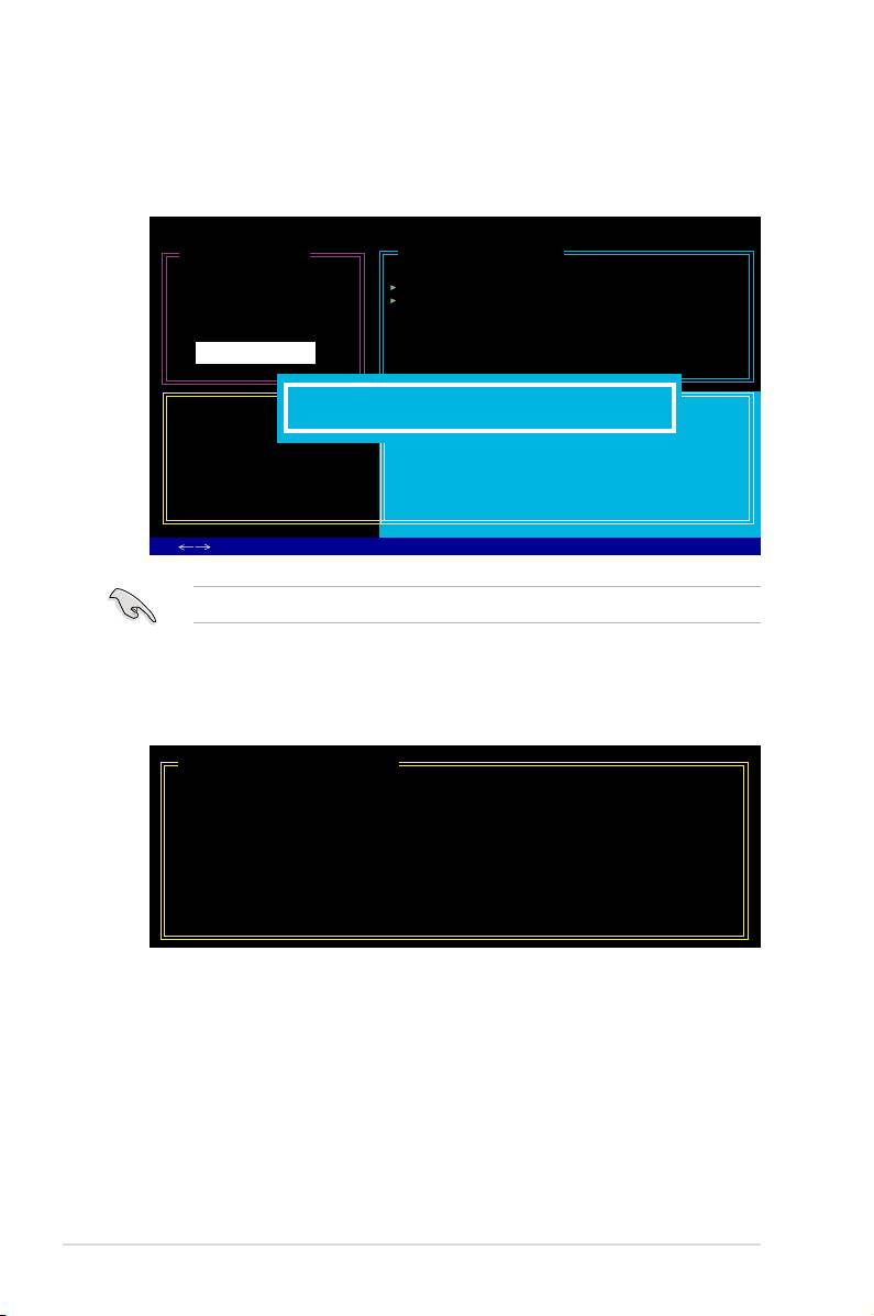
Creating a RAID set
1. In the main JMB363 RAID BIOS menu, highlight Create RAID Disk Drive
using the up/down arrow key then press <Enter>.
[Main Menu]
Create RAID Disk Drive
Delete RAID Disk Drive
Revert HDD to Non-RAID
Solve Mirror Conict
Rebuild Mirror Drive
Save and Exit Setup
Exit Without Saving
5-52 Chapter 5: Software support

2. When the Level item is highlighted, use the up/down arrow key to select the
RAID set that you want to create.
[Create New RAID]
[Create New RAID]
Name : JRAID
Name : JRAID
Level: 0-Stripe
Level: 1-Mirror
Disks: Select Disk
Disks: Select Disk
Block: 128 KB
Block: N/A
Size : 319 GB
Size : 159 GB
Conrm Creation
Conrm Creation
3. When the Disks item is highlighted, use the up/down arrow key to highlight
an HDD that you want to belong to the RAID set, then press the space bar to
conrm selection. Repeat the process until the HDDs are selected.
A selected HDD shows a
sign before it.
[Hard Disk Drive List]
Model Name Capacity Type/Status
HDD0: HDS722516VLSA80 XXX GB Non-RAID
HDD1: HDS722516DLA380 XXX GB Non-RAID
4. Key in the RAID volume capacity. Use the up/down arrow to choose the block
size. The default value indicates the maximum allowed capacity.
[Create New RAID]
Name : JRAID
Level: 0-Stripe
Disks: Select Disk
Block: 128 KB
Size : 319 GB
Conrm Creation
ASUS P5E3 Premium/WiFi-AP @n 5-53
5. When done, press <Enter> to conrm the creation of the RAID set. A dialogue
box appears to conrm the action. Press <Y> to conrm; otherwise, press
<N>.
JMicron Technology Corp. PCI-to-SATA II/IDE RAID Controller BIOS v0.97
[Create New RAID]
[Hard Disk Drive List]
Name: JRAID
Model Name Available Type/Status
Level: 0-Stripe
HDD0: HDS722516VLSA80 164 GB Non-RAID
Disks: Select Disk
HDD1: HDS722516DLA380 164 GB Non-RAID
Block: 128 KB
Size : 319 GB
Conrm Creation
[RAID Disk Drive List]
Create RAID on the selected HDD (Y/N)? Y
CONFIRM RAID CREATION
ALL DATA ON THE SELECTED HARD DISK
WILL BE LOST WHEN EXIT WITH SAVING
[
TAB]-Switch Window [
↑↓
]-Select Item [ENTER]-Action [ESC]-Exit
Pressing <Y> deletes all the data in the HDDs.
6. The following screen appears, displaying the relevant information about the
RAID set you created.
[RAID Disk Drive List]
Model Name RAID Level Capacity Status Members(HDDx)
RDD0: JRAID 0-Stripe XXX GB Normal 01
5-54 Chapter 5: Software support
Deleting a RAID set
1. In the main JMB363 RAID BIOS menu, highlight Delete RAID Disk Drive
using the up/down arrow key then press <Enter>.
[Main Menu]
Create RAID Disk Drive
Delete RAID Disk Drive
Revert HDD to Non-RAID
Solve Mirror Conict
Rebuild Mirror Drive
Save and Exit Setup
Exit Without Saving
2. Use the space bar to select the RAID set you want to delete.
A selected set shows a
sign before it. Press the <Del> key to delete the
set.
3. A dialogue box appears to conrm the action. Press <Y> to conrm;
otherwise, press <N>.
JMicron Technology Corp. PCI-to-SATA II/IDE RAID Controller BIOS v0.97
[Main Menu]
[Hard Disk Drive List]
Create RAID Disk Drive
Model Name Capacity Type/Status
Delete RAID Disk Drive
HDD0: HDS722516VLSA80 164 GB RAID Inside
Revert HDD to Non-RAID
HDD1: HDS722516DLA380 164 GB RAID Inside
Solve Mirror Conict
Rebuild Mirror Drive
Save and Exit Setup
Exit Without Saving
[RAID Disk Drive List]
ALL DATA ON THE RAID WILL BE LOST!!
Model Name RAID Level Capacity Status
ARE YOU SURE TO DELETE (Y/N)? Y
Members(HDDx)
RDD0: JRAID 0-Stripe XXX GB Normal 01
[
TAB]-Switch Window [
↑↓
]-Select Item [ENTER]-Action [ESC]-Exit
Pressing <Y> deletes all the data in the HDDs.
ASUS P5E3 Premium/WiFi-AP @n 5-55
Resetting disks to non-RAID
• An HDD that has been previously congured as part of another RAID set in
another platform is called a broken RAID HDD. When you install a broken
RAID HDD, you cannot select this HDD when configuring a RAID set
through the JMB363 utility.
• If you still want to use this broken RAID HDD as part of the RAID set
congured through the JMB363, you may do so by resetting the disk to non-
RAID. You will, however, lose all data and previous RAID congurations.
To reset disks to non-RAID:
1. In the main JMB363 RAID BIOS menu, highlight Revert HDD to non-RAID
using the up/down arrow key then press <Enter>.
[Main Menu]
Create RAID Disk Drive
Delete RAID Disk Drive
Revert HDD to Non-RAID
Solve Mirror Conict
Rebuild Mirror Drive
Save and Exit Setup
Exit Without Saving
2. Use the space bar to select the HDD that you want to reset to non-RAID.
A selected HDD shows a
sign before it.
3. A dialogue box appears to conrm the action. Press <Y> to conrm;
otherwise, press <N>.
Pressing <Y> deletes all the data in the HDD.
5-56 Chapter 5: Software support

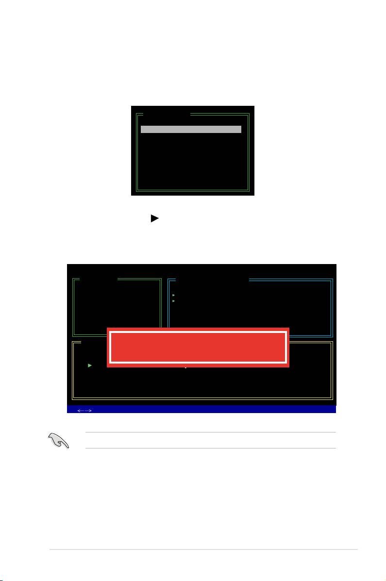
Solving a Mirror conict
A Mirror conict occurs when both disks in a RAID 1 (Mirror) conguration are
unplugged from the system in turn, then plugged in again. Since both disks contain
exactly the same data, the system will be unable to determine which of the two
is the source drive. This option allows you to set the source drive and rebuild the
Mirror drive according to the contents of the source drive.
To solve a Mirror conict:
1. In the main JMB363 RAID BIOS menu, highlight Solve Mirror Conict using
the up/down arrow key then press <Enter>.
[Main Menu]
Create RAID Disk Drive
Delete RAID Disk Drive
Revert HDD to Non-RAID
Solve Mirror Conict
Rebuild Mirror Drive
Save and Exit Setup
Exit Without Saving
2. Use the space bar to select the HDD that you want to set as source drive.
The selected HDD shows a
sign before it.
3. Using the <TAB>, move to the RAID Disk Drive List menu and highlight the
RAID set that you want to rebuild. Press <Del> to begin rebuilding the Mirror
conguration.
A status bar at the bottom of the screen shows the progress of the rebuilding.
JMicron Technology Corp. PCI-to-SATA II/IDE RAID Controller BIOS v0.97
[Main Menu]
[Hard Disk Drive List]
Create RAID Disk Drive
Model Name Capacity Type/Status
Delete RAID Disk Drive
HDD0: HDS722516VLSA80 164 GB RAID Inside
Revert HDD to Non-RAID
HDD1: HDS722516DLA380 164 GB RAID Inside
Solve Mirror Conict
Rebuild Mirror Drive
Save and Exit Setup
Exit Without Saving
[RAID Disk Drive List]
Model Name RAID Level Capacity Status
Members(HDDx)
RDD0: JRAID 1-Mirror XXX GB Rebuild 01
Rebuilding... 01%, please wait...
ASUS P5E3 Premium/WiFi-AP @n 5-57

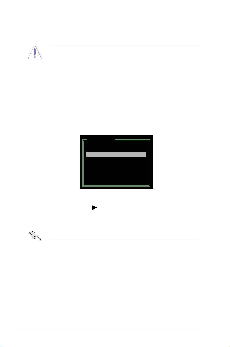
Rebuilding a Mirror Drive
When one of the disks in a RAID 1 (Mirror) conguration is unplugged from the
system, then plugged in again, a dialogue box appears to ask you to rebuild the
Mirror drive. Press <Y> to conrm; otherwise, press <N>.
This option allows you to rebuild the Mirror drive later and synchronize the data
between two hard disks.
To rebuild a Mirror drive:
1. In the main JMB363 RAID BIOS menu, highlight Rebuild Mirror Drive using
the up/down arrow key then press <Enter>.
[Main Menu]
Create RAID Disk Drive
Delete RAID Disk Drive
Revert HDD to Non-RAID
Solve Mirror Conict
Rebuild Mirror Drive
Save and Exit Setup
Exit Without Saving
2. Using the <TAB>, move to the RAID Disk Drive List menu and highlight the
RAID set that you want to rebuild. Press <Del> to begin rebuilding the Mirror
conguration.
A status bar at the bottom of the screen shows the progress of the rebuilding.
JMicron Technology Corp. PCI-to-SATA II/IDE RAID Controller BIOS v0.97
[Main Menu]
[Hard Disk Drive List]
Create RAID Disk Drive
Model Name Capacity Type/Status
Delete RAID Disk Drive
HDD0: HDS722516VLSA80 164 GB RAID Inside
Revert HDD to Non-RAID
HDD1: HDS722516DLA380 164 GB RAID Inside
Solve Mirror Conict
Rebuild Mirror Drive
Save and Exit Setup
Exit Without Saving
[RAID Disk Drive List]
Model Name RAID Level Capacity Status
Members(HDDx)
RDD0: JRAID 1-Mirror XXX GB Rebuild 01
Rebuilding... 01%, please wait...
Saving the settings and exiting setup
When you have nished, highlight Save & Exit Setup using the up/down arrow key
then press <Enter> to save the current RAID conguration and exit the JMB363
RAID BOS utility.
A dialogue box appears to conrm the action. Press <Y> to conrm; otherwise,
press <N> to return to the JMB RAID BIOS menu.
5-58 Chapter 5: Software support

5.5 Creating a RAID driver disk
®
A oppy disk with the RAID driver is required when installing Windows
XP/Vista
and later operating system on a hard disk drive that is included in a RAID set. For
Windows Vista user, you can create a RAID driver disk with a oppy disk drive or a
USB ash disk drive.
5.5.1 Creating a RAID driver disk without entering the OS
To create a RAID driver disk without entering the OS:
1. Boot your computer.
2. Press <Del> during POST to enter the BIOS setup utility.
3. Set the optical drive as the primary boot device.
4. Insert the support CD into the optical drive.
5. Save changes and exit BIOS.
6. Press any key when the system prompts “Press any key to boot from the
optical drive.”
7. When the menu appears, press <1> to create a RAID driver disk.
8. Insert a formatted oppy disk into the oppy drive then press <Enter>.
9. Follow succeeding screen instructions to complete the process.
®
5.5.2 Creating a RAID driver disk in Windows
®
To create a RAID driver disk in Windows
:
®
1. Start Windows
.
2. Place the motherboard support CD into the optical drive.
3. Go to the Make Disk menu, then click
Intel ICH9R 32/64 bit RAID Driver
®
Disk
to create an Intel
ICH9R RAID driver disk or the
Make JMicron
JMB36X 32/64-bit RAID Driver
to create a JMicron JMB363 RAID driver
disk.
4. Insert a oppy disk into the oppy disk drive or connect a USB ash disk if
you are using Windows Vista OS.
5. Follow succeeding screen instructions to complete the process.
Write-protect the oppy disk to avoid computer virus infection.
ASUS P5E3 Premium/WiFi-AP @n 5-59

To install the RAID driver in Windows XP:
1. During the OS installation, the system prompts you to press the <F6> key to
install third-party SCSI or RAID driver.
2. Press <F6> then insert the oppy disk with RAID driver into the oppy disk
drive.
3. When prompted to select the SCSI adapter to install, make sure you select
Intel(R) SATA RAID Controller (Desktop ICH9R) and JMicron JMB363.
4. Follow the succeeding screen instructions to complete the installation.
®
To install the RAID driver in Windows
Vista:
1. Insert the oppy disk/USB device with RAID driver into the oppy disk drive/USB
port.
2. During the OS installation, select
JMicron JMB363.
3. Follow the succeeding screen instructions to complete the installation.
5-60 Chapter 5: Software support
