Dell Precision 650 – страница 4
Инструкция к Компьютеру Dell Precision 650
Оглавление
Back to Contents Page
Memory
DellPrecision™Workstation650andDellPrecisionWorkstation450ServiceManual
Memory Installation Guidelines
Removing a Memory Module
Adding a Memory Module
You can increase your computer memory by installing memory modules on the system board. For information on the type of memory supported by your
computer, see "Specifications" in your User's Guide.
Memory Installation Guidelines
l Memory module connectors must be upgraded in matched pairs. Memory module connectors 1 and 2 must contain modules of identical size, type, speed,
and number of chips and memory module connectors 3 and 4 must contain modules of identical size, type, speed, and number of chips. To locate the
memory sockets on the system board, see the system board components illustration (for the Dell Precision 450 computer, see "System Board
Components" or for the Dell Precision 650 computer, see "System Board Components") or the system board label inside your computer.
l Before you install new memory modules, download the most recent BIOS for your computer from the Dell Support website at support.dell.com.
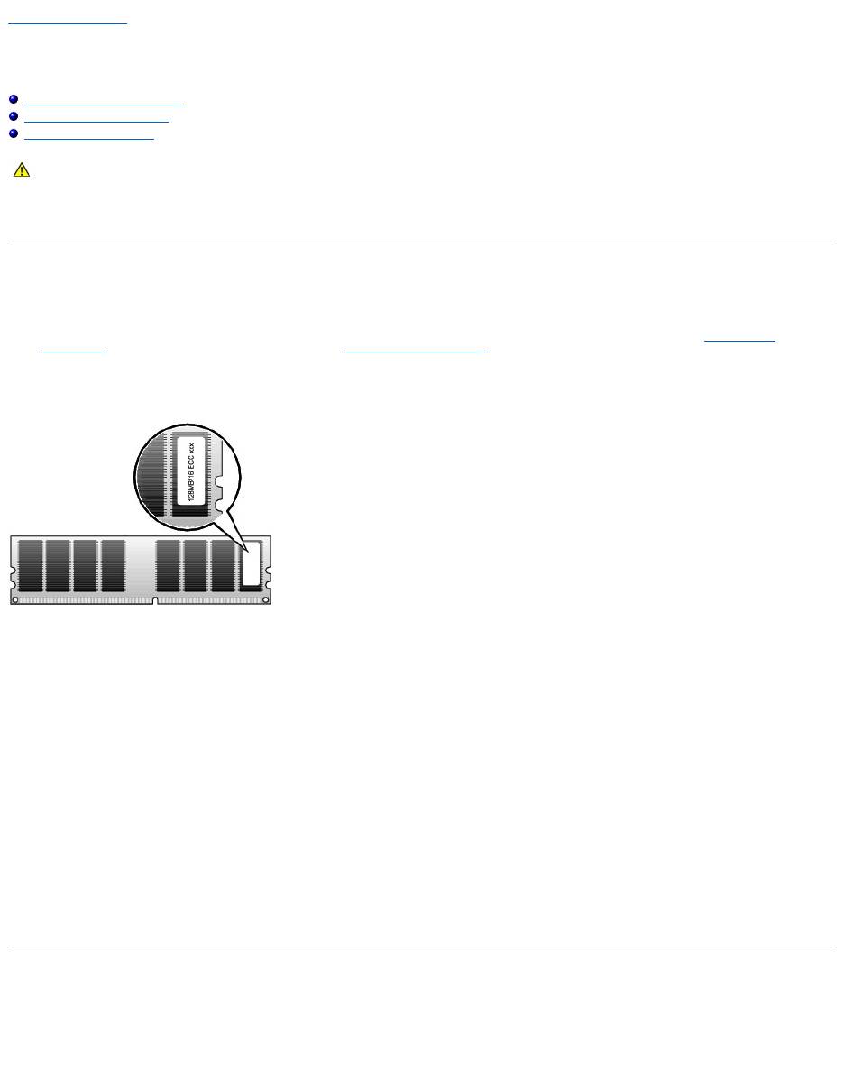
Memory Module Label
Addressing Memory With 4-GB Configurations
Your computer supports a maximum of 4GB of memory when using four 1-GB DIMMs. Current operating systems, such as Microsoft®Windows®2000 and
Windows XP, can only utilize a maximum of 4 GB of address space; however, the amount of memory available to the operating system is slightly less than 4
GB. Certain components within the computer require address space in the 4-GB range. Any address space reserved for these components cannot be used by
computer memory. The following is a list of components that require memory address space:
l System ROM
l APIC(s)
l Integrated PCI devices, such as network connector, SCSI controller, and IEEE 1394 controller
l PCI and AGP cards
l The AGP Aperture size specified in system setup
At start-up the BIOS identifies the components that require address space. The BIOS dynamically calculates the amount of reserved address space required. It
then subtracts the reserved address space from 4 GB to determine the amount of usable space.
l If the total installed computer memory is less than the usable space, all installed computer memory is available for use only by the operating system.
l If the total installed computer memory is equal to or greater than the usable address space, a small portion of installed memory is available for use by
the operating system.
Removing a Memory Module
1. Press down and outward on the securing clips.
2. Grasp the module and pull up.
If the module is difficult to remove, gently ease the module back and forth to remove it from the connector.
CAUTION: Before you begin any of the procedures in this section, follow the safety instructions in the System Information Guide.
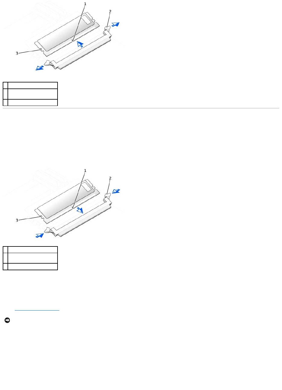
Adding a Memory Module
1. Press out the securing clip at each end of the memory module connector.
2. Align the notch on the bottom of the module with the crossbar in the connector.
3. Insert the module into the connector, ensuring that it fits into the guides at each end of the connector. Carefully press each end of the module into
place.
The memory module socket has alignment keys that allow the memory module to be installed in the socket only one way.
4. Pull up on the securing clips to lock the modules into place.
If you insert the module correctly, the securing clips snap into the cutouts at each end of the module.
When the memory module is properly seated in the socket, the securing clips on the memory module socket should align with the securing clips on the
other sockets with memory modules installed.
5. Close the computer cover.
6. Connect your computer and devices to electrical outlets, and turn them on.
The computer detects that the new memory does not match the existing configuration information and generates the following message:
The amount of system memory has changed.
Strike the F1 key to continue, F2 to run the setup utility
7. Press <F2> to enter system setup and check the value for System Memory.
The computer should have changed the value of System Memory to reflect the newly installed memory. Verify the new total. If it is correct, skip to step
10.
8. If the memory total is incorrect, turn off and disconnect your computer and devices from electrical outlets.
1
notch
2
memory module securing
clips (2)
3
alignment keys
1
notch
2
memory module securing
clips (2)
3
alignment keys
NOTICE: To connect a network cable, first plug the cable into the network wall jack and then plug it into the computer.

9. Open the computer cover and check the installed memory modules to ensure that they are seated properly in their sockets. Then repeat steps step 4
through step 7.
10. When the System Memory total is correct, press <Esc> to exit system setup.
11. Run the Dell Diagnostics to verify that the memory modules are operating properly.
Back to Contents Page
Back to Contents Page
Microprocessor Airflow Shroud — DellPrecision™650Computer
DellPrecision™Workstation650andDellPrecisionWorkstation450ServiceManual
Removing the Microprocessor Airflow Shroud
Installing the Microprocessor Airflow Shroud
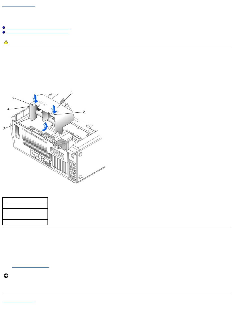
Removing the Microprocessor Airflow Shroud
1. Press down and back on the indentations at the top corners of the shroud.
The top anchor tabs disengage from the anchor slots.
2. Lift the airflow shroud out of the computer.
Installing the Microprocessor Airflow Shroud
1. Insert the bottom anchor tabs into the anchor slots.
2. Align and insert the side anchor tabs into the anchor slots.
3. Press the indentations until the top anchor tabs on the shroud snap securely into place.
4. Close the computer cover.
5. Connect your computer and devices to electrical outlets, and turn them on.
Back to Contents Page
CAUTION: Before you begin any of the procedures in this section, follow the safety instructions in the System Information Guide.
1
airflow shroud
2
indentations (2)
3
bottom anchor tabs (2)
4
side anchor tabs (2)
5
top anchor tabs (2)
NOTICE: To connect a network cable, first plug the cable into the network wall jack and then plug it into the computer.
Back to Contents Page
Power Supply — DellPrecision™650Computer
DellPrecision™Workstation650andDellPrecisionWorkstation450ServiceManual
Removing the Power Supply
Replacing the Power Supply
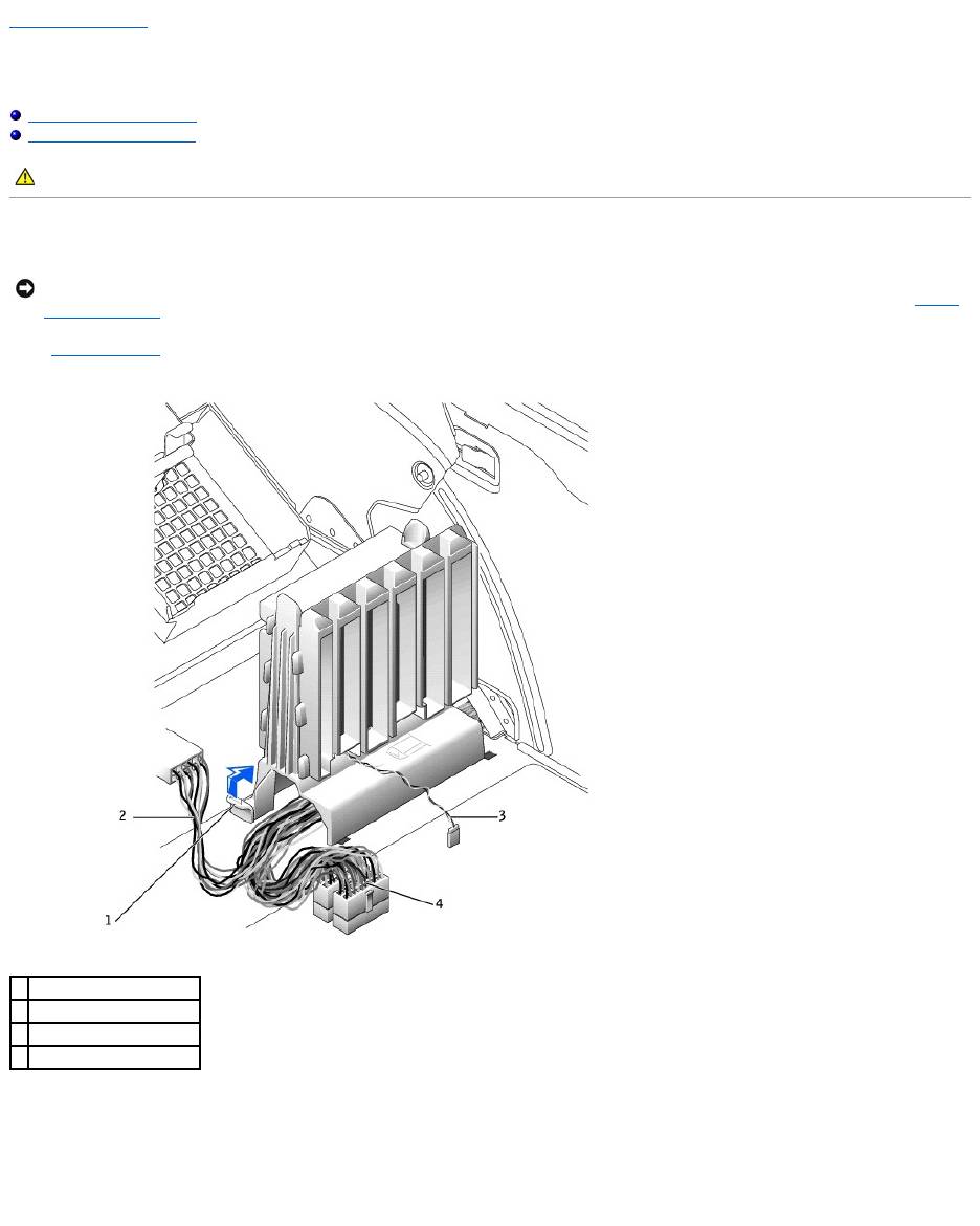
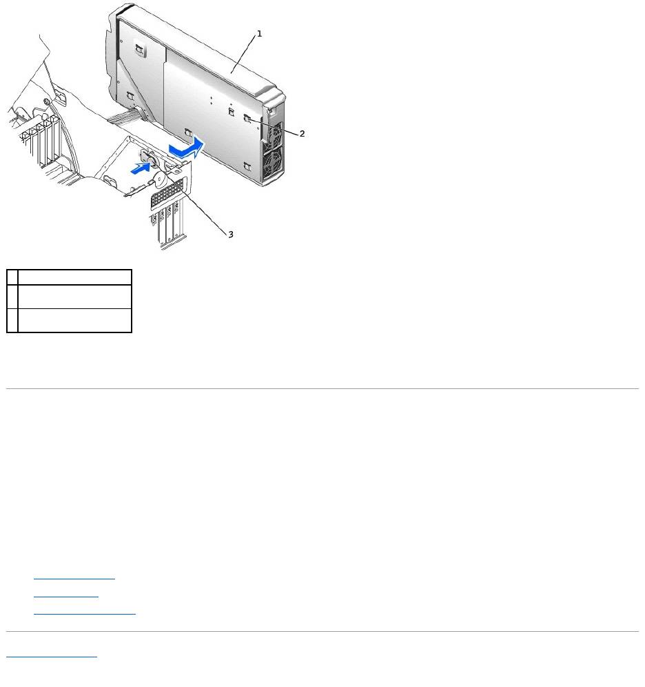
Removing the Power Supply
1. Remove the cards and the card fan.
2. Disconnect the power supply cables and the card fan cable.
3. Remove the card fan guide:
a. Pull up on the fan-guide release button.
b. Slide the card fan guide to the right.
c. Lift the card fan guide out of the four securing slots in the computer.
4. While pressing the power-supply release button, slide the power supply toward the back of the computer.
CAUTION: Before you begin any of the procedures in this section, follow the safety instructions in the System Information Guide.
NOTICE: Before disconnecting a device from the computer, wait 10 to 20 seconds after disconnecting the computer from its electrical outlet. Before
removing a component from the system board, verify that the standby power light on the system board has turned off. To locate this light, see "System
Board Components."
1
fan-guide release button
2
drive power cable
3
card fan cable
4
power supply cables
5. Lift the power supply away from the computer.
6. Slide the power supply cables out of the computer (through the hole).
Replacing the Power Supply
1. Slide the power supply cables through the hole into the computer.
2. Insert the power-supply securing tabs into the power-supply securing slot on the computer, ensuring that each securing tab is connected to its slot on
the computer.
3. Slide the power supply toward the front of the computer.
4. Install the card fan guide:
a. Place the card fan guide into the four securing slots in the computer.
b. Slide the card fan guide to the left until it locks into position.
5. Connect the power supply cables and the card fan cable.
6. Replace the card fan.
7. Install the cards.
8. Close the computer cover and restart the computer.
Back to Contents Page
1
power supply
2
power-supply securing tab
(5)
3
power-supply release
button
Back to Contents Page
System Board
DellPrecision™Workstation650andDellPrecisionWorkstation450ServiceManual
Removing the System Board
Replacing the System Board
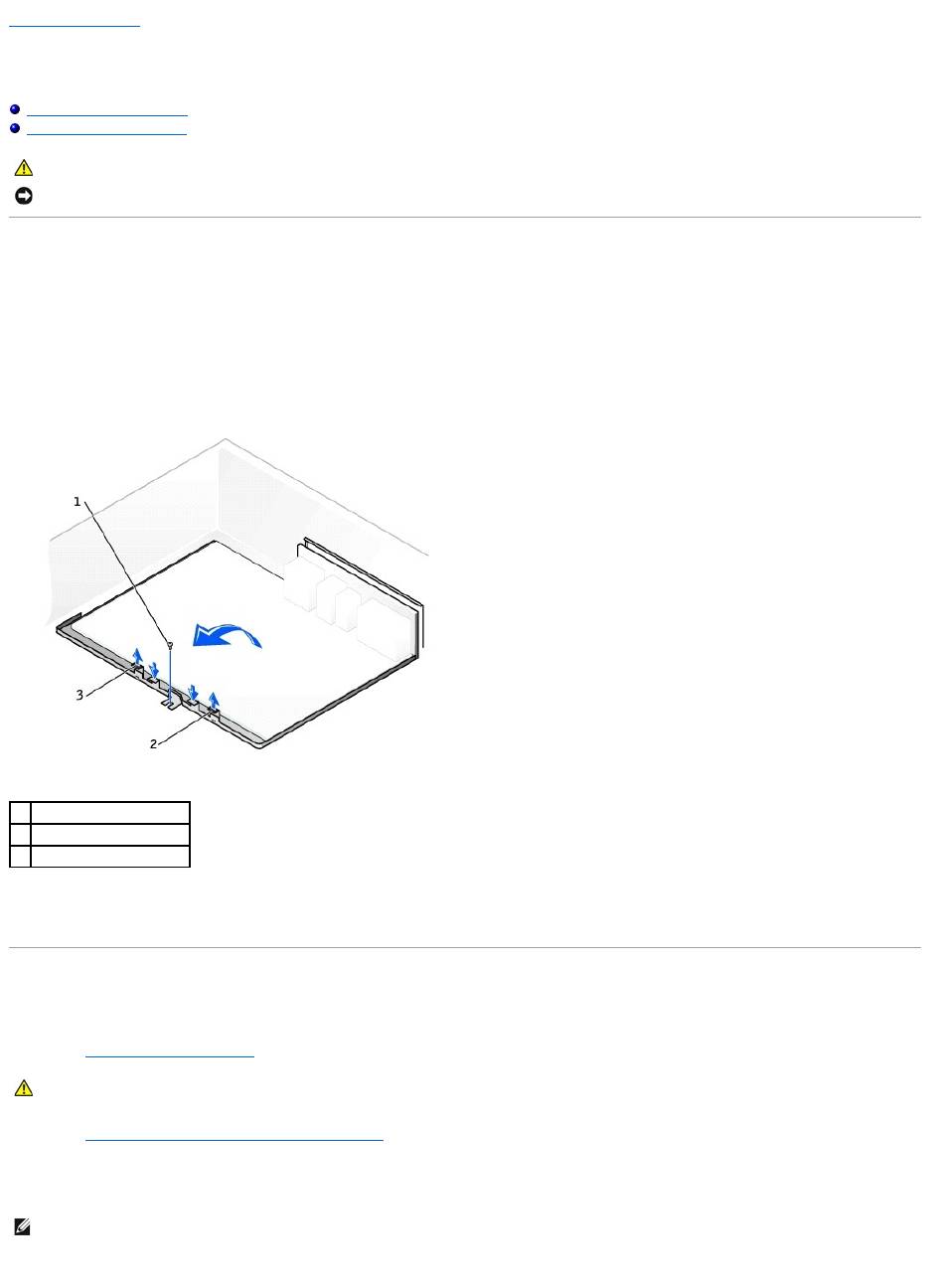
Removing the System Board
1. Remove any components that restrict access to the system board.
2. Disconnect all cables from the system board.
3. Before you remove the existing system board assembly, visually compare the replacement system board to the existing system board to make sure
that you have the correct part.
4. Remove the system board screw.
5. Pull up on the two tabs, slide the system board assembly toward the front of the computer, and then lift the asembly up and away.
6. Place the system board assembly that you just removed next to the replacement system board.
Replacing the System Board
1. Transfer components from the existing system board to the replacement system board:
a. Remove the memory modules and install them on the replacement board.
b. Remove the heat-sink assembly and microprocessor from the existing system board and transfer them to the replacement system board.
2. Configure the settings of the replacement system board.
3. Set the jumpers on the replacement system board so they are identical to the ones on the existing board.
4. Orient the replacement board by aligning the notches on the bottom of the board with the tabs on the computer.
CAUTION: Before you begin any of the procedures in this section, follow the safety instructions in the System Information Guide.
NOTICE: The system board and metal tray are connected and are removed as one piece.
1
system board screw
2
tab
3
tab
CAUTION: The microprocessor package and heat-sink assembly can get hot. To avoid burns, ensure that the package and assembly have had
sufficient time to cool before you touch them.
NOTE: Some components and connectors on the replacement system board may be in different locations than the corresponding connectors on the
existing system board.

5. Slide the system board assembly toward the back of the computer until the assembly clicks into position.
6. Replace any components and cables that you removed from the system board.
Back to Contents Page
