Dell Precision 650 – страница 2
Инструкция к Компьютеру Dell Precision 650
Оглавление
See the documentation for your operating system for instructions.
15. Test the hard drive by running the Dell Diagnostics.
16. If the drive you just installed is the primary drive, install your operating system on the hard drive.
Floppy Drive
Removing a Floppy Drive
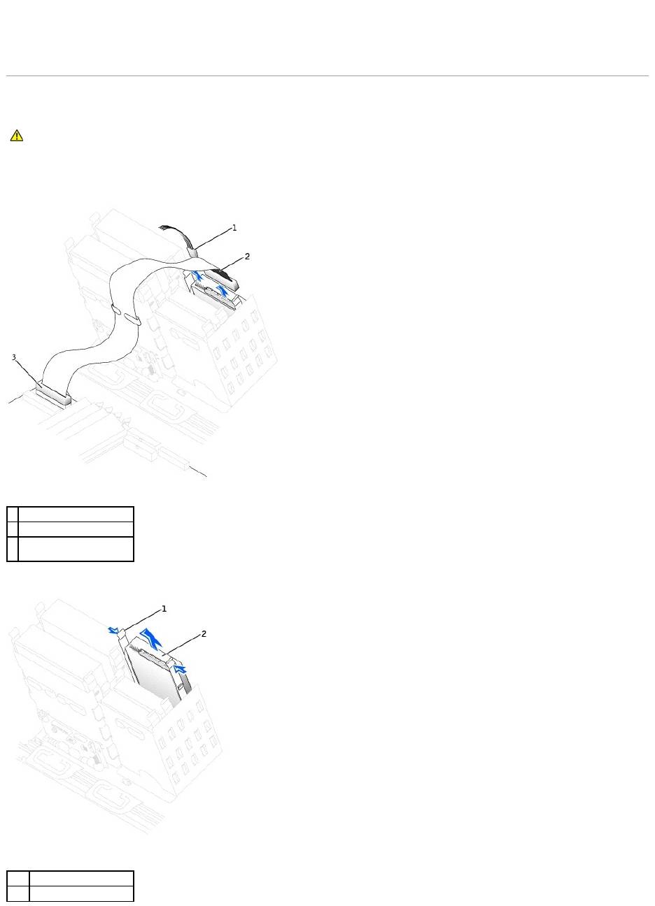
1. Disconnect the power and floppy-drive cables from the back of the floppy drive.
2. Press inward on the two tabs on the sides of the drive, slide the drive upward, and remove it from the floppy-drive bay.
CAUTION: Before you begin any of the procedures in this section, follow the safety instructions in the System Information Guide.
1
power cable
2
floppy-drive cable
3
floppy-drive connector
(DSKT)
1
tabs (2)
2
floppy drive
Installing a Floppy Drive
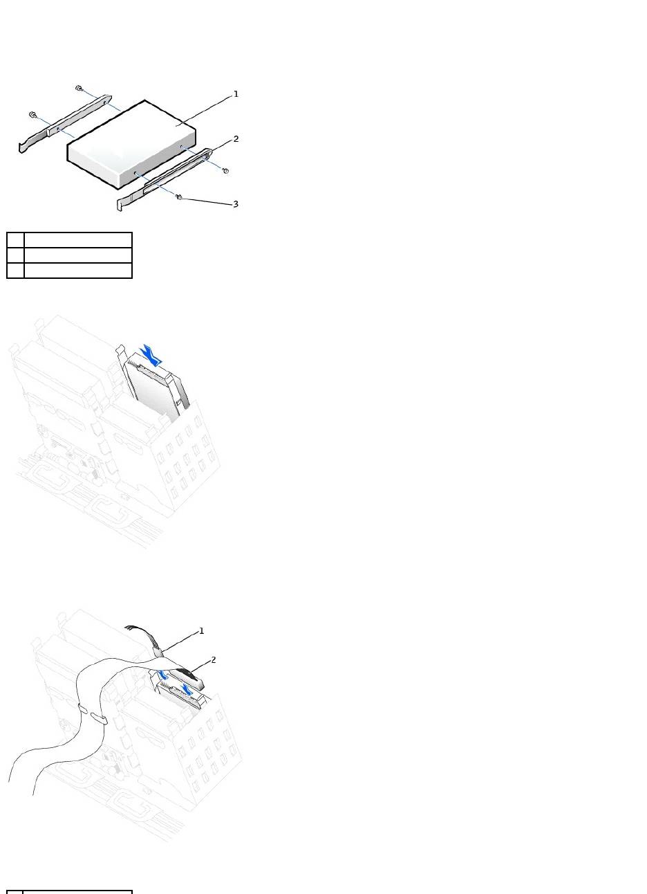
1. If you are replacing a drive and the the new drive does not have the bracket rails attached, remove the rails from the old drive by removing the two
screws that secure each rail to the drive. Attach the bracket to the new drive by aligning the screw holes on the drive with the screw holes on the
bracket rails and then inserting and tightening all four screws (two screws on each rail).
2. Gently slide the drive into place until the tabs securely click into position.
3. Attach the power and floppy-drive cables to the floppy drive.
1
drive
2
bracket rails (2)
3
screws (4)

4. If you are installing a new floppy drive rather than replacing a drive, remove the front-panel inserts.
From inside the drive bay, gently press on each side of the insert until it pops out.
5. Check all cable connections, and fold cables out of the way to provide airflow for the fan and cooling vents.
6. Close the computer cover.
7. Connect your computer and devices to electrical outlets, and turn them on.
See the documentation that came with the drive for instructions on installing any software required for drive operation.
8. Enter system setup and update the appropriate Diskette Drive A option to reflect the size and capacity of your new floppy drive.
9. To verify that your computer works correctly, run the Dell Diagnostics.
CD/DVD Drive
Removing a CD/DVD Drive
1. Disconnect the power and CD/DVD drive cables from the back of the drive.
2. Press inward on the two tabs on the sides of the drive, and then slide the drive upward and remove it from the drive bay.
1
power cable
2
floppy-drive cable
NOTICE: To connect a network cable, first plug the cable into the network wall jack and then plug it into the computer.
CAUTION: Before you begin any of the procedures in this section, follow the safety instructions in the System Information Guide.
1
CD/DVD drive cable
2
power cable

Installing a CD/DVD Drive
1. If you are installing a new drive, unpack the drive and prepare it for installation.
Check the documentation that accompanied the drive to verify that the drive is configured for your computer. If you are installing an IDE drive, configure
the drive for the cable select setting.
2. Connect the new drive to the set of rails that are attached to the inside of the computer cover. If a set of rails is not attached inside the cover, contact
Dell.
3. If you are installing a replacement drive and the new drive does not have the bracket rails attached, remove the rails from the old drive by removing
the two screws that secure each rail to the drive. Attach the bracket to the new drive by aligning the screw holes on the drive with the screw holes on
the bracket rails and then inserting and tightening all four screws (two screws on each rail).
4. Gently slide the drive into place until the tabs securely click into position.
1
tabs (2)
2
CD/DVD drive
1
drive
2
bracket rails (2)
3
screws (4)

5. If you are installing a drive that has its own controller card, install the controller card in an expansion slot.
See the documentation that accompanied the drive and controller card to verify that the configuration is correct for your computer.
6. Connect the power and CD/DVD drive cables to the drive.
If you are adding a drive that has an audio cable, connect the audio cable to the audio connector on the system board.
7. If you are installing a new CD/DVD drive rather than replacing a drive, remove the front-panel inserts.
From inside the drive bay, gently press on each side of the insert until it pops out.
8. Check all cable connections, and fold cables out of the way to provide airflow for the fan and cooling vents.
9. Close the computer cover.
1
audio cable (some drives
do not have this cable)
2
CD/DVD drive cable
3
power cable

10. Connect your computer and devices to electrical outlets, and turn them on.
See the documentation that came with the drive for instructions on installing any software required for drive operation.
11. Update your configuration information by setting the appropriate Drive option (0 or 1) under Drives: Secondary to Auto. See "Advanced Features" in
your User's Guide for more information.
12. To verify that your computer works correctly, run the Dell Diagnostics.
Back to Contents Page
NOTICE: To connect a network cable, first plug the cable into the network wall jack and then plug it into the computer.
Back to Contents Page
Power Supply — DellPrecision™450Computer
DellPrecision™Workstation650andDellPrecisionWorkstation450ServiceManual
Removing the Power Supply
Replacing the Power Supply
Removing the Power Supply
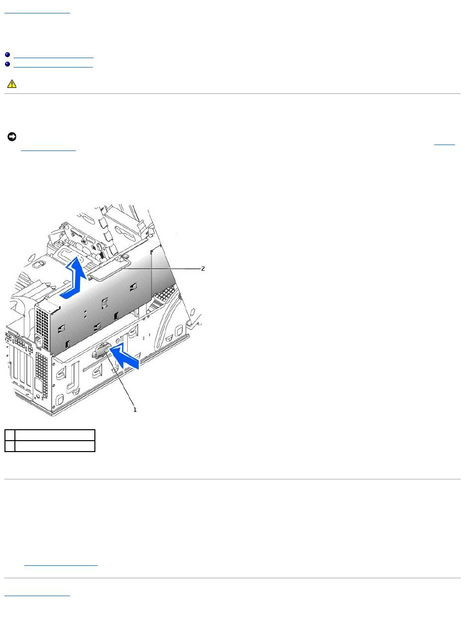
1. Disconnect the power supply cables from the system board.
2. Lift the handle on the power supply.
3. While pressing the release button, slide the power supply toward the front of the computer.
4. Lift the power supply away from the computer.
Replacing the Power Supply
1. Insert the power-supply securing tabs into the power-supply securing slot on the computer, ensuring that each securing tab is connected to its slot on
the computer.
2. Slide the power supply toward the back of the computer.
3. Connect the power supply cables.
4. Close the computer cover and restart the computer.
Back to Contents Page
CAUTION: Before you begin any of the procedures in this section, follow the safety instructions in the System Information Guide.
NOTICE: Before disconnecting a device from the computer, wait 10 to 20 seconds after disconnecting the computer from its electrical outlet. Before
removing a component from the system board, verify that the standby power light on the system board has turned off. To locate this light, see "System
Board Components."
1
release button
2
power supply handle
Back to Contents Page
Drive Door — DellPrecision™650Computer
DellPrecision™Workstation650andDellPrecisionWorkstation450ServiceManual
Removing the Drive Door
Replacing the Drive Door
Removing the Drive Door
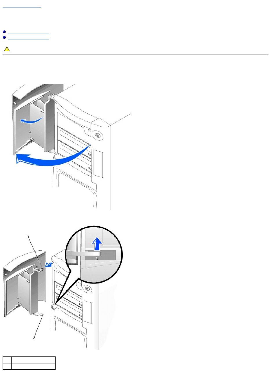
1. Open the drive door.
2. Unsnap the top hinge and pull the top of the drive door outward, away from the computer.
CAUTION: Before you begin any of the procedures in this section, follow the safety instructions in the System Information Guide.
1
top hinge
2
bottom hinge

3. Lift the bottom hinge away from the computer.
Replacing the Drive Door
To replace the drive door, perform the removal procedure in reverse.
Back to Contents Page
Back to Contents Page
Microprocessor Airflow Shroud — DellPrecision™450Computer
DellPrecision™Workstation650andDellPrecisionWorkstation450ServiceManual
Removing the Microprocessor Airflow Shroud
Installing the Microprocessor Airflow Shroud
Removing the Microprocessor Airflow Shroud
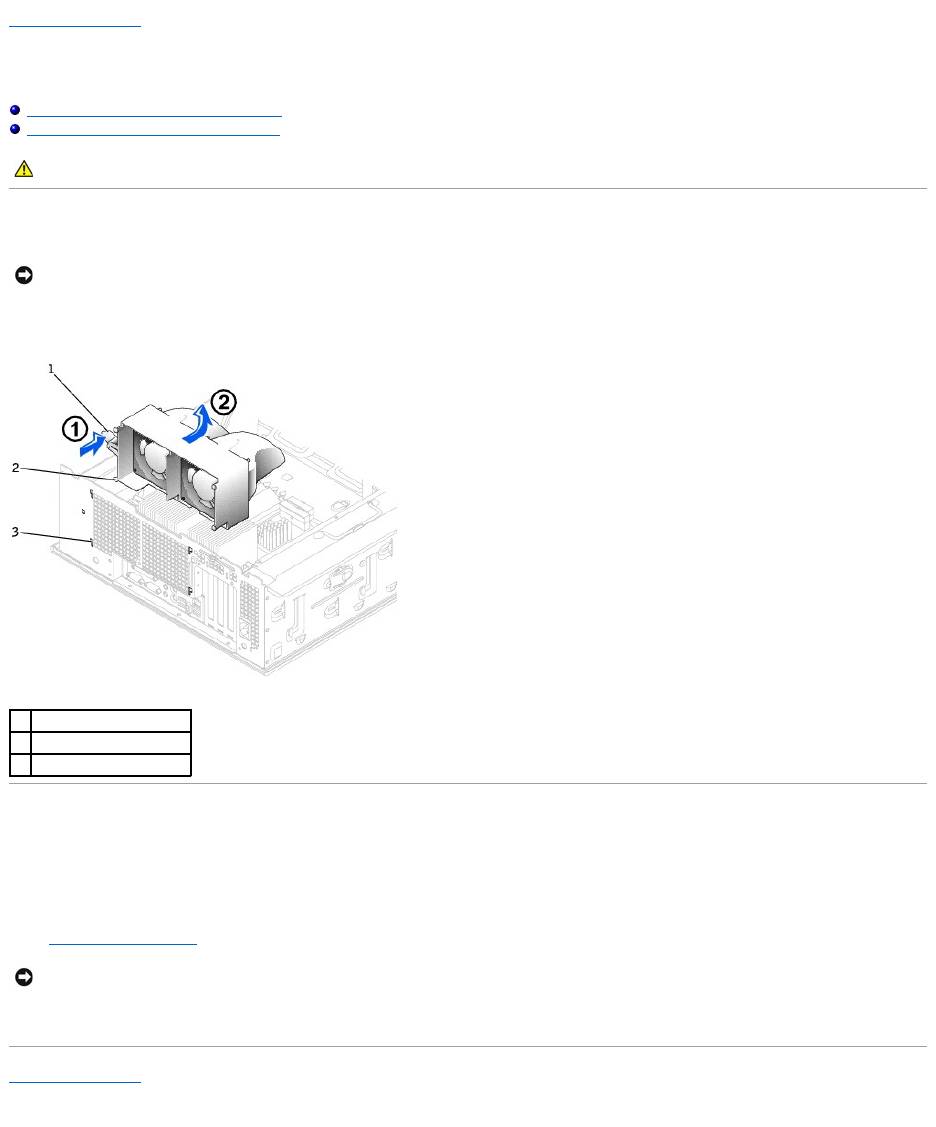
1. Press the shroud release lever towards the front of the computer and lift the shroud up to disengage the anchors.
2. Once the shroud has been disengaged from the anchors, unplug the fan cables from their connectors on the system board.
Installing the Microprocessor Airflow Shroud
1. Attach both fan power cables to the connectors on the system board.
2. Align the anchor tabs with the securing slots.
3. Gently press the shroud until the anchor tabs snap securely into place.
4. Close the computer cover.
5. Connect your computer and devices to electrical outlets, and turn them on.
Back to Contents Page
CAUTION: Before you begin any of the procedures in this section, follow the safety instructions in the System Information Guide.
NOTICE: To avoid damaging the fan power cables, do not slide the shroud too quickly.
1
shroud release lever
2
anchor tabs
3
anchor slots
NOTICE: To connect a network cable, first plug the cable into the network wall jack and then plug it into the computer.
Back to Contents Page
Card Fan and Guide — Dell Precision 650 Computer
DellPrecision™Workstation650andDellPrecisionWorkstation450ServiceManual
Removing the Card Fan and Guide
Replacing the Card Fan and Guide
The Card Fan Guide
Removing the Card Fan and Guide
1. Disconnect the fan power cable from its connector on the system board. To locate this connector, see "System Board Components."
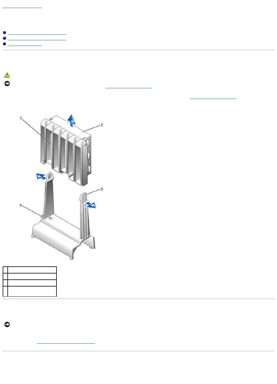
2. Press the release tabs outward from the card fan guide, and lift the fan up and out of the guide.
Replacing the Card Fan and Guide
Insert the bottom of the fan into the clips on the card fan guide. Then press the top of the fan toward the card fan guide until the tabs on the card fan guide
grasp the fan. See "Removing the Card Fan and Guide."
The Card Fan Guide
If you need to remove the card fan guide, pull up on the card-fan guide-release button and slide the guide up and out of the computer. To replace the card fan
guide, insert the card-fan guide anchor tabs into the slots on the computer and slide the guide into position.
CAUTION: Before you begin any of the procedures in this section, follow the safety instructions in the System Information Guide.
NOTICE: Before disconnecting a device from the computer or removing a component from the system board, verify that the standby power light on the
system board has turned off. To locate this light, see "System Board Components."
1
card fan guide
2
card fan
3
release button (2)
4
card-fan guide-release
button
NOTICE: Ensure that the fan is properly installed on the guide. When the fan is properly installed, the fan manufacturer label faces the expansion-card
guide, and the fan power cable extends toward the system board.

Back to Contents Page
Back to Contents Page
Front Panel
DellPrecision™Workstation650andDellPrecisionWorkstation450ServiceManual
Removing the Front Panel
Replacing the Front Panel
Removing the Front Panel
1. Disconnect and remove all disk drives (for more information, see "Drives — DellPrecision™650Computer" or "Drives — DellPrecision™450Computer."
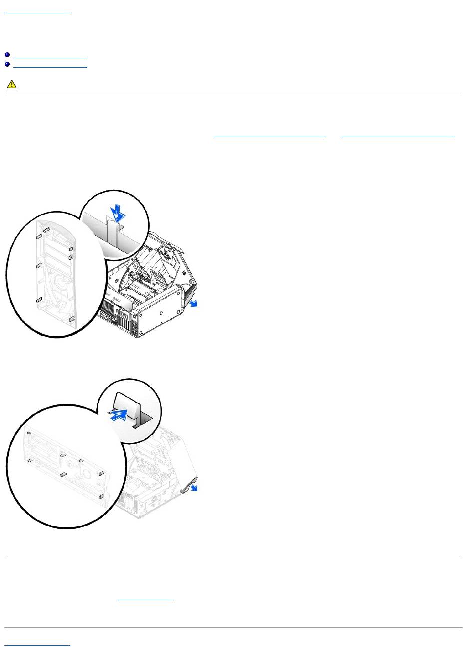
2. Release the front panel by pressing each of the front-panel release tabs.
The Dell Precision 650 computer has seven release tabs and the Dell Precision 450 computer has seven release tabs.
Dell Precision 650 Computer
Dell Precision 450 Computer
3. Close the computer cover halfway and pull the front panel away from the computer.
Replacing the Front Panel
To replace the front panel, perform the removal procedure in reverse.
Back to Contents Page
CAUTION: Before you begin any of the procedures in this section, follow the safety instructions in the System Information Guide.

Back to Contents Page
I/O Panel
DellPrecision™Workstation650andDellPrecisionWorkstation450ServiceManual
I/O Panel Components for the Dell Precision 650 Computer
I/O Panel Components for the Dell Precision 450 Computer
Removing the I/O Panel
Replacing the I/O Panel
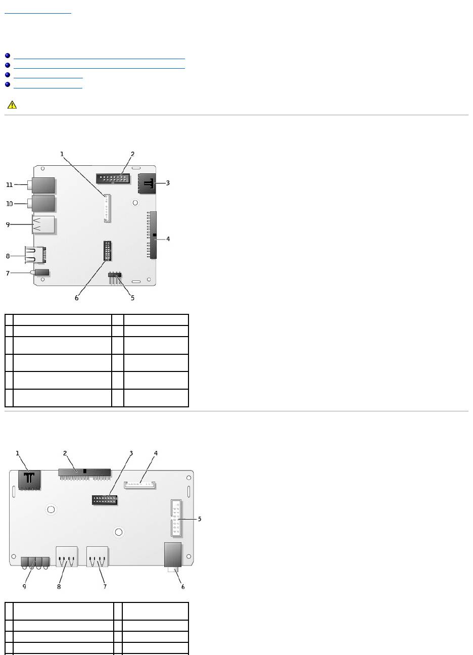
I/O Panel Components for the Dell Precision 650 Computer
I/O Panel Components for the Dell Precision 450 Computer
CAUTION: Before you begin any of the procedures in this section, follow the safety instructions in the System Information Guide.
1
front-panel audio connector
7
diagnostic lights (4)
2
control panel connector
8
IEEE 1394 connector
3
chassis-intrusion switch
connector
9
USB 2.0 connectors
(2)
4
system board connector
10
microphone
connector
5
speaker connector
11
headphone
connector
6
front-panel USB/IEEE 1394
connector
1
chassis-intrusion switch
connector
6
headphone
connector
2
system board connector
7
USB 2.0 connector
3
USB 2.0 connector
8
USB 2.0 connector
4
front-panel audio connector
9
diagnostic lights (4)
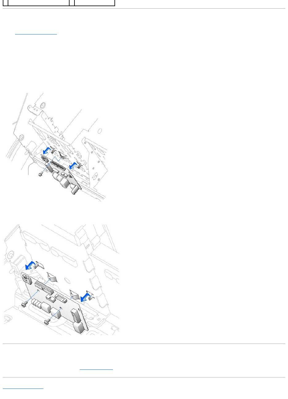
Removing the I/O Panel
1. Remove the front panel.
2. Disconnect the control panel cable from the control panel connector.
3. Disconnect the front-panel cable from the system board.
4. Remove all cables that are connected to the front I/O panel.
5. From inside the cover, remove the mounting screw that secures the front I/O panel to the computer.
6. Remove the front I/O panel from the computer.
Dell Precision 650 Computer
Dell Precision 450 Computer
Replacing the I/O Panel
To replace the front I/O panel, perform the removal procedure in reverse.
Back to Contents Page
5
control panel connector

Back to Contents Page
Inside Your Computer — DellPrecision™650Computer
DellPrecision™Workstation650andDellPrecisionWorkstation450ServiceManual
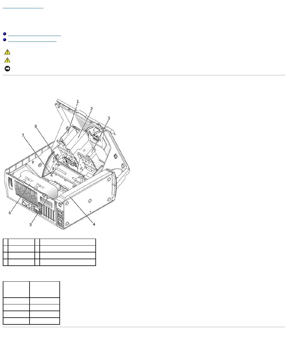
Inside View of Your Computer
System Board Components
Inside View of Your Computer
Cable Colors
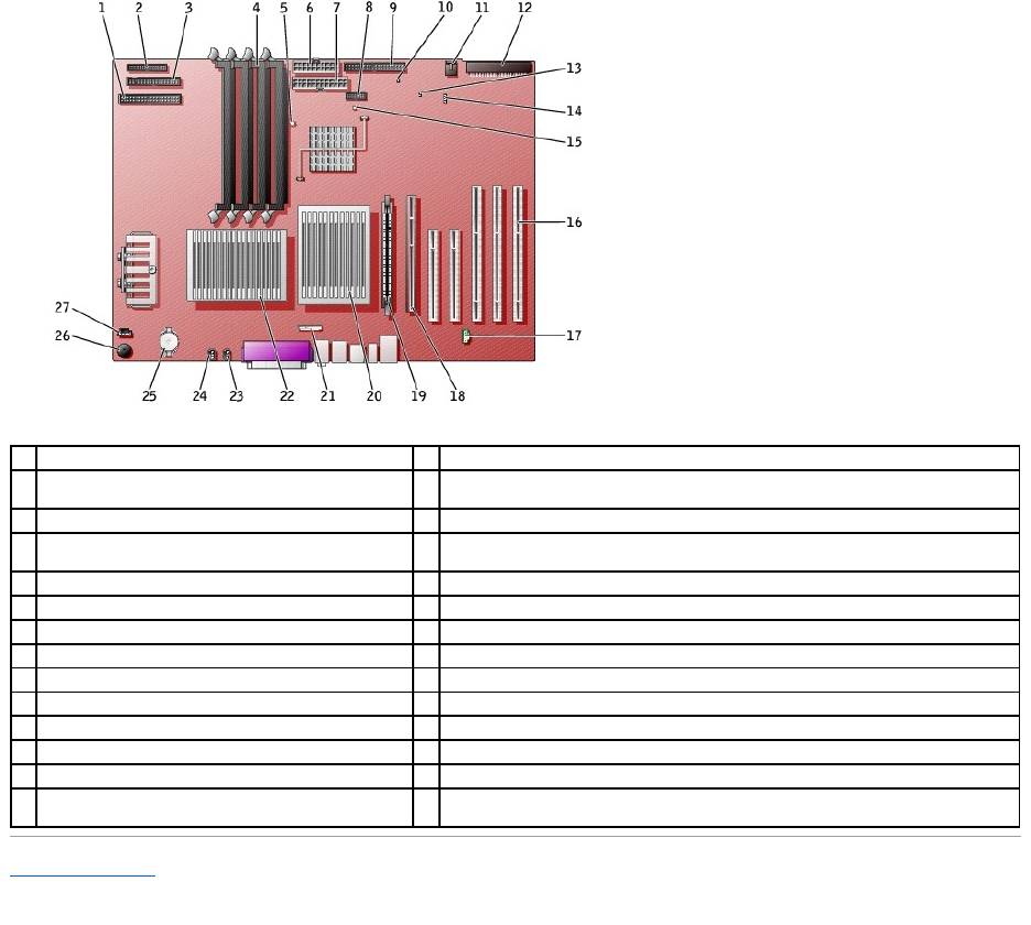
System Board Components
CAUTION: Before you begin any of the procedures in this section, follow the safety instructions in the System Information Guide.
CAUTION: To avoid electrical shock, always unplug your computer from the electrical outlet before opening the cover.
NOTICE: Be careful when opening the computer cover to ensure that you do not accidentally disconnect cables from the system board.
1
floppy drive
5
padlock ring
2
CD/DVD drive
6
microprocessor airflow shroud
3
hard drive
7
system board
4
power supply
8
chassis intrusion switch
Device
Cable Color
Hard drive
Blue pull tab
Floppy drive
Black pull tab
CD/DVD drive
Orange pull tab
I/O Panel
Yellow pull tab
Back to Contents Page
1
CD/DVD drive connector (IDE2)
15
standby power light (AUX_PWR_LED)
2
I/O panel connector (I/O PANEL)
16
PCI card connectors (PCI1, PCI2 [32-bit connectors], PCI3 , PCI4, and PCI5 [64-bit PCI-X
connectors])
3
floppy-drive connector (DISKETTE)
17
telephony connector (MODEM)
4
memory module connectors (DIMM_1, DIMM_2, DIMM_3,
DIMM_4)
18
AGP Pro card connector (AGP)
5
suspend-to-RAM light (STR_LED)
19
VRM connector (VRM)(for a second microprocessor only)
6
power connector (POWER 2)
20
microprocessor and heat-sink connector (CPU_1)
7
power connector (POWER 1)
21
front-panel audio connector (FP2AUDIO)
8
front-panel USB/IEEE 1394 connector (USB)
22
microprocessor and heat-sink connector (CPU_0)
9
hard-drive connector (IDE1)
23
microprocessor fan connector (FAN_P1)
10
real-time clock reset jumper (RTCRST)
24
microprocessor fan connector (FAN_P0)
11
card fan connector (FAN)
25
battery socket (BATTERY)
12
SCSI drive connector (SCSI)
26
internal speaker (SPKR)
13
password jumper (PSWD)
27
CD drive audio cable connector (CD_IN)
14
auxiliary LED add-in storage adapter connector
(AUX_LED)
Back to Contents Page
Closing the Computer Cover
DellPrecision™Workstation650andDellPrecisionWorkstation450ServiceManual
1. Ensure that all cables are connected, and fold cables out of the way.
2. Ensure that no tools or extra parts are left inside the computer.
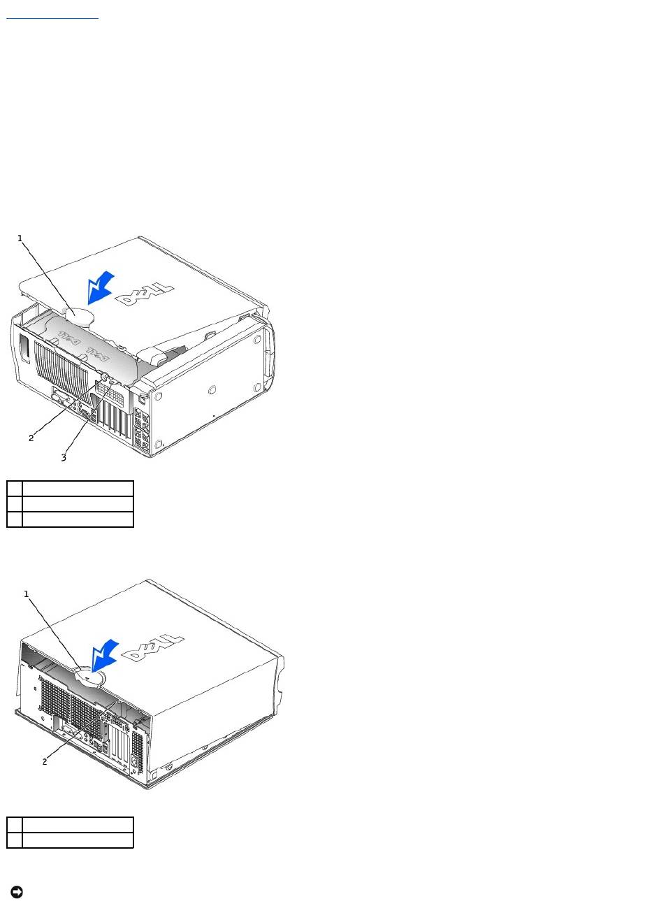
3. Close the computer cover:
a. Pivot the cover down and into position.
b. If your computer has a baffle, ensure that the baffle is correctly positioned by guiding it into place as you lower the cover.
c. Press down on the cover to close it.
d. Once the cover is closed, slide the release latch to the right until the latch clicks into place.
Dell Precision 650 Computer
Dell Precision 450 Computer
4. If you are using a padlock to secure your computer, install the padlock.
1
cover release latch
2
security cable slot
3
padlock ring
1
cover release latch
2
padlock ring
NOTICE: To connect a network cable, first plug the cable into the network wall jack and then plug it into the computer.
