Dell PowerEdge 860 – страница 5
Инструкция к Компьютеру Dell PowerEdge 860
Оглавление

Troubleshooting External Connections
Loose or improperly connected cables are the most likely source of problems for the system, monitor, and
other peripherals (such as a printer, keyboard, mouse, or other external device). Ensure that all external
cables are securely attached to the external connectors on your system. See Figure 1-1 for the front-panel
connectors and Figure 1-2 for the back-panel connectors on your system.
Troubleshooting the Video Subsystem
Problem
• Monitor is not working properly.
• Video memory is faulty.
Action
1
Check the system and power connections to the monitor.
2
Determine whether the system has monitors attached to both the front and rear video connectors.
The system supports only one monitor attached to either the front or rear video connector. When a
monitor is connected to the front panel, and the back-panel video connector is disabled.
If two monitors are attached to the system, disconnect one monitor. If the problem is not resolved,
continue to the next step.
3
Check the system and power connections to the monitor.
4
Run the appropriate online diagnostic test. See "Using Dell PowerEdge Diagnostics" on page 93.
If the tests run successfully, the problem is not related to video hardware.
If the tests fail, see "Getting Help" on page 103.
Troubleshooting the Keyboard
Problem
• System message indicates a problem with the keyboard.
• Keyboard is not functioning properly.
Action
1
Run the appropriate online diagnostic test. See "Using Dell PowerEdge Diagnostics" on page 93.
2
Press each key on the keyboard, and examine the keyboard and its cable for signs of damage.
3
Swap the faulty keyboard with a working keyboard.
If the problem is resolved, replace the faulty keyboard. See "Getting Help" on page 103.
If the problem is not resolved, see "Getting Help" on page 103.
Troubleshooting Your System 81

Troubleshooting the Mouse
Problem
• System message indicates a problem with the mouse.
• Mouse is not functioning properly.
Action
1
Run the appropriate online diagnostic test. See "Using Dell PowerEdge Diagnostics" on page 93.
If the test fails, continue to the next step.
2
Examine the mouse and its cable for signs of damage.
3
Swap the faulty mouse with a working mouse.
If the problem is resolved, replace the faulty mouse. See "Getting Help" on page 103.
If the problem is not resolved, see "Getting Help" on page 103.
Troubleshooting Basic I/O Functions
Problem
• Error message indicates a problem with a serial port.
• Device connected to a serial port is not operating properly.
Action
1
Enter the System Setup program and ensure that the serial port is enabled. See "Using the System
Setup Program" on page 29.
2
If the problem is confined to a particular application, see the application documentation for specific
port configuration requirements that the program may require.
3
Run the appropriate online diagnostic test. See "Using Dell PowerEdge Diagnostics" on page 93.
If the tests run successfully but the problem persists, see "Troubleshooting a Serial I/O Device" on
page 82.
Troubleshooting a Serial I/O Device
Problem
• Device connected to the serial port is not operating properly.
82 Troubleshooting Your System

Action
1
Turn off the system and any peripheral devices connected to the serial port.
2
Swap the serial interface cable with a working cable, and turn on the system and the serial device.
If the problem is resolved, replace the interface cable. See "Getting Help" on page 103.
3
Turn off the system and the serial device, and swap the device with a comparable device.
4
Turn on the system and the serial device.
If the problem is resolved, replace the serial device. See "Getting Help" on page 103.
If the problem persists, see "Getting Help" on page 103.
Troubleshooting a USB Device
Problem
• System message indicates a problem with a USB device.
• Device connected to a USB port is not operating properly.
Action
1
Enter the System Setup program, and ensure that the USB ports are enabled. See "Using the System
Setup Program" on page 29.
2
Turn off the system and any USB devices.
3
Disconnect the USB devices, and connect the malfunctioning device to the other USB connector.
4
Turn on the system and then turn on the reconnected device.
If the problem is resolved, the USB connector might be defective. See "Getting Help" on page 103.
5
If possible, swap the interface cable with a working cable.
If the problem is resolved, replace the interface cable. See "Getting Help" on page 103.
6
Turn off the system and the USB device, and swap the device with a comparable device.
7
Turn on the system and the USB device.
If the problem is resolved, replace the USB device. See "Getting Help" on page 103.
If the problem persists, see "Getting Help" on page 103.
Troubleshooting a NIC
Problem
• NIC cannot communicate with network.
Troubleshooting Your System 83

Action
1
Run the appropriate online diagnostic test. See "Using Dell PowerEdge Diagnostics" on page 93.
2
Check the appropriate indicator on the NIC connector. See "NIC Indicator Codes" on page 15.
• If the link indicator does not light, check all cable connections.
• If the activity indicator does not light, the network driver files might be damaged or missing.
Remove and reinstall the drivers if applicable. See the NIC's documentation.
• Change the autonegotiation setting, if possible.
• Use another connector on the switch or hub.
If you are using a NIC card instead of an integrated NIC, see the documentation for the NIC card.
3
Ensure that the appropriate drivers are installed and the protocols are bound. See the NIC's
documentation.
4
Enter the System Setup program and confirm that the NICs are enabled. See "Using the System Setup
Program" on page 29.
5
Ensure that the NICs, hubs, and switches on the network are all set to the same data transmission
speed. See the network equipment documentation.
6
Ensure that all network cables are of the proper type and do not exceed the maximum length.
Responding to a Systems Management Software Alert Message
Systems management software monitors critical system voltages and temperatures, fans, and hard drives in
the system. Alert messages appear in the
Alert Log
window. For information about the
Alert Log
window,
see the systems management software documentation.
Troubleshooting a Wet System
Problem
• Liquid spilled on the system.
• Excessive humidity.
Action
CAUTION: Only trained service technicians are authorized to remove the system cover and access any of the
components inside the system. Before performing any procedure, see your Product Information Guide for
complete information about safety precautions, working inside the computer and protecting against electrostatic
discharge.
1
Turn off the system and attached peripherals, and disconnect the system from the electrical outlet.
2
Open the system. See "Opening the System" on page 46.
3
Remove all expansion cards installed in the system. See "Removing an Expansion Card" on page 65.
84 Troubleshooting Your System

4
Let the system dry thoroughly for at least 24 hours.
5
Close the system. See "Closing the System" on page 47.
6
Reconnect the system to the electrical outlet, and turn on the system and attached peripherals.
If the system does not start properly, see "Getting Help" on page 103.
7
If the system starts properly, shut down the system and reinstall all of the expansion cards that you
removed. See "Installing an Expansion Card" on page 63.
8
Run the appropriate online diagnostic test. See "Using Dell PowerEdge Diagnostics" on page 93.
If the tests fail, see "Getting Help" on page 103.
Troubleshooting a Damaged System
Problem
• System was dropped or damaged.
Action
CAUTION: Only trained service technicians are authorized to remove the system cover and access any of the
components inside the system. Before performing any procedure, see your Product Information Guide for
complete information about safety precautions, working inside the computer and protecting against electrostatic
discharge.
1
Open the system. See "Opening the System" on page 46.
2
Ensure that the following components are properly installed:
• Expansion cards
• Power supplies
•Fans
3
Ensure that all cables are properly connected.
4
Close the system. See "Closing the System" on page 47.
5
Run the system board tests in the system diagnostics. See "Running the System Diagnostics" on
page 93.
If the tests fail, see "Getting Help" on page 103.
Troubleshooting Your System 85
Troubleshooting the System Battery
Problem
• System message indicates a problem with the battery.
• System Setup program loses system configuration information.
• System date and time do not remain current.
NOTE: If the system is turned off for long periods of time (for weeks or months), the NVRAM may lose its system
configuration information. This situation is caused by a defective battery.
Action
1
Re-enter the time and date through the System Setup program. See "Using the System Setup Program"
on page 29.
2
Turn off the system and disconnect it from the electrical outlet for at least one hour.
3
Reconnect the system to the electrical outlet and turn on the system.
4
Enter the System Setup program.
If the date and time are not correct in the System Setup program, replace the battery. See "System
Battery" on page 49.
If the problem is not resolved by replacing the battery, see "Getting Help" on page 103.
NOTE: Some software may cause the system time to speed up or slow down. If the system seems to operate
normally except for the time kept in the System Setup program, the problem may be caused by software rather than
by a defective battery.
Troubleshooting the Power Supply
Problem
• System-status indicators are amber.
Action
CAUTION: Only trained service technicians are authorized to remove the system cover and access any of the
components inside the system. Before performing any procedure, see your Product Information Guide for
complete information about safety precautions, working inside the computer and protecting against electrostatic
discharge.
1
Run the appropriate online diagnostics test. See "Using Dell PowerEdge Diagnostics" on page 93.
2
Turn off the system and attached peripherals, and disconnect the system from the electrical outlet.
3
Open the system. See "Opening the System" on page 46.
86 Troubleshooting Your System

4
Ensure that the power supply is properly installed by removing and reinstalling it. See "Power Supply"
on page 61.
If the problem persists, remove the faulty power supply. See "Removing the Power Supply" on page 61.
5
Install a new power supply. See "Installing the Power Supply" on page 62.
If the problem persists, see "Getting Help" on page 103.
Troubleshooting System Cooling Problems
Problem
• Systems management software issues a fan-related error message.
Action
Ensure that none of the following conditions exist:
• Ambient temperature is too high.
• External airflow is obstructed.
• Cables inside the system obstruct airflow.
• An individual cooling fan has failed. See "Troubleshooting a Fan" on page 87.
Troubleshooting a Fan
Problem
• System-status indicator is amber.
• Systems management software issues a fan-related error message.
Action
CAUTION: Only trained service technicians are authorized to remove the system cover and access any of the
components inside the system. Before performing any procedure, see your Product Information Guide for
complete information about safety precautions, working inside the computer and protecting against electrostatic
discharge.
1
Run the appropriate diagnostic test. See "Using Dell PowerEdge Diagnostics" on page 93.
2
Open the system. See "Opening the System" on page 46.
3
Ensure that the faulty fan's power cable is firmly attached to the fan power connector. See "Fan
Assembly" on page 57.
NOTE: Wait 30 seconds for the system to recognize the fan and determine whether it is working properly.
Troubleshooting Your System 87

4
If the problem is not resolved, install a new fan. See "Fan Assembly" on page 57.
If the replacement fan is working properly, close the system. See "Closing the System" on page 47.
If the replacement fan does not operate, see "Getting Help" on page 103.
Troubleshooting System Memory
Problem
• Faulty memory module.
• Faulty system board.
• Diagnostic indicator code indicates a problem with system memory.
Action
CAUTION: Only trained service technicians are authorized to remove the system cover and access any of the
components inside the system. Before performing any procedure, see your Product Information Guide for
complete information about safety precautions, working inside the computer and protecting against electrostatic
discharge.
1
If the system is operational, run the appropriate online diagnostic test. See "Using Dell PowerEdge
Diagnostics" on page 93.
If diagnostics indicates a fault, follow the corrective action(s) provided by the diagnostic program. If
the problem is not resolved or if the system is not operational, proceed to step 2.
2
Turn off the system and attached peripherals, unplug the system from the power source and press the
power button, and reconnect the system to power.
3
Turn on the system and attached peripherals and, as the system boots, note the messages on the
screen.
If the amount of system memory detected during POST does not match the amount of memory
installed, proceed to the next step.
If an error message appears, go to step 12.
4
Enter the System Setup program and check the system memory setting. See "Using the System Setup
Program" on page 29.
If the amount of memory installed matches the system memory setting, go to step 12.
5
Turn off the system and attached peripherals, and disconnect the system from the electrical outlet.
6
Open the system. See "Opening the System" on page 46.
7
Ensure that the memory banks are populated correctly. See "Memory Module Installation Guidelines"
on page 68.
If the memory modules are populated correctly, continue to the next step.
8
Reseat the memory modules in their sockets. See "Installing Memory Modules" on page 69.
88 Troubleshooting Your System
9
Close the system. See "Closing the System" on page 47.
10
Reconnect the system to its electrical outlet, and turn on the system and attached peripherals.
11
Enter the System Setup program and check the system memory setting. See "Using the System Setup
Program" on page 29. If the amount of memory installed still does not match the system memory
setting, proceed to the next step.
12
Turn off the system and attached peripherals, and disconnect the system from its electrical outlet.
13
Open the system. See "Opening the System" on page 46.
NOTE: Several configurations for the memory modules exist; see "Memory Module Installation Guidelines" on
page 68.
14
If a diagnostic test or error message indicates a specific memory module as faulty, swap or replace the
module. Otherwise, swap the memory module in socket 1 with a module of the same type and capacity
that is known to be good. See "Installing Memory Modules" on page 69.
15
Close the system. See "Closing the System" on page 47.
16
Reconnect the system to its electrical outlet, and turn on the system and attached peripherals.
17
As the system boots, observe any error message that appears and the diagnostic indicators on the front
of the system.
18
If the memory problem is still indicated, repeat step 12 through step 17 for each memory module
installed until the faulty memory module is replaced.
If the problem persists after all memory modules have been checked, see "Getting Help" on page 103.
Troubleshooting an Optical Drive
Problem
• System cannot read data from a CD or DVD.
• Optical drive indicator does not blink during boot.
Action
CAUTION: Only trained service technicians are authorized to remove the system cover and access any of the
components inside the system. Before performing any procedure, see your Product Information Guide for
complete information about safety precautions, working inside the computer and protecting against electrostatic
discharge.
1
Try using a different CD or DVD in the optical drive.
2
Enter the System Setup program and ensure that the drive’s IDE controller is enabled. See "Using the
System Setup Program" on page 29.
3
Run the appropriate online diagnostic test. See "Using Dell PowerEdge Diagnostics" on page 93.
4
Turn off the system and attached peripherals, and disconnect the system from the electrical outlet.
5
Open the system. See "Opening the System" on page 46.
Troubleshooting Your System 89

6
Ensure that the interface cable is securely connected to the optical drive and to the controller.
7
Ensure that a power cable is properly connected to the drive.
8
Close the system. See "Closing the System" on page 47.
9
Reconnect the system to the electrical outlet, and turn on the system and attached peripherals.
If the problem is not resolved, see "Getting Help" on page 103.
Troubleshooting a Hard Drive
Problem
• Device driver error.
• One or more hard drives not recognized by the system.
Action
CAUTION: Only trained service technicians are authorized to remove the system cover and access any of the
components inside the system. Before performing any procedure, see your Product Information Guide for
complete information about safety precautions, working inside the computer and protecting against electrostatic
discharge.
NOTICE: This troubleshooting procedure can destroy data stored on the hard drive. Before you proceed, back up
all files on the hard drive.
1
Run the appropriate online diagnostics test. See "Using Dell PowerEdge Diagnostics" on page 93.
Depending on the results of the diagnostics test, proceed as needed through the following steps.
2
If you are experiencing problems with multiple hard drives, skip to step 5. For a problem with a single
hard drive, continue to the next step.
3
If your system has a SAS RAID controller, perform the following steps.
a
Restart the system and press <Ctrl><R> to enter the host adapter configuration utility program.
See the documentation supplied with the host adapter for information about the configuration
utility.
b
Ensure that the hard drive has been configured correctly for the RAID.
c
Exit the configuration utility and allow the system to boot to the operating system.
4
Ensure that the required device drivers for your SAS controller card or SAS RAID controller are
installed and are configured correctly. See the operating system documentation for more information.
5
Check the System Setup program to verify that the SAS controller is enabled and the hard drives
connected to the controller are detected.
6
Check the cable connections inside the system:
a
Turn off the system, including any attached peripherals, and disconnect the system from the
electrical outlet.
90 Troubleshooting Your System

b
Open the system. See "Opening the System" on page 46.
c
Verify that the cable connections between the hard drive(s) and the drive controller are correct,
whether the connections are to the SATA connectors on the system board, a SAS expansion card,
or a SAS RAID controller.
d
Verify that the SAS or SATA cables are securely seated in their connectors.
e
Close the system. See "Closing the System" on page 47.
f
Reconnect the system to the electrical outlet, and turn on the system and attached peripherals.
If the problem persists,
see "Getting Help
" on page 103
.
Troubleshooting Expansion Cards
NOTE: When troubleshooting an expansion card, see the documentation for your operating system and the
expansion card.
Problem
• Error message indicates a problem with an expansion card.
• Expansion card performs incorrectly or not at all.
Action
CAUTION: Only trained service technicians are authorized to remove the system cover and access any of the
components inside the system. Before performing any procedure, see your Product Information Guide for
complete information about safety precautions, working inside the computer and protecting against electrostatic
discharge.
1
Run the appropriate online diagnostic test. See "Using Dell PowerEdge Diagnostics" on page 93.
2
Turn off the system and attached peripherals, and disconnect the system from the electrical outlet.
3
Open the system. See "Opening the System" on page 46.
4
Ensure that each expansion card is firmly seated in its connector. See "Installing an Expansion Card"
on page 63.
5
Close the system. See "Closing the System" on page 47.
6
Reconnect the system to the electrical outlet, and turn on the system and attached peripherals.
If the problem persists, go to the next step.
7
Turn off the system and attached peripherals, and disconnect the system from the electrical outlet.
8
Open the system. See "Opening the System" on page 46.
9
Remove all expansion cards installed in the system. See "Removing an Expansion Card" on page 65.
10
Close the system. See "Closing the System" on page 47.
11
Reconnect the system to the electrical outlet, and turn on the system and attached peripherals.
Troubleshooting Your System 91

12
Run the appropriate online diagnostic test.
If the tests fail, see "Getting Help" on page 103.
13
For each expansion card you removed in step 9, perform the following steps:
a
Turn off the system and attached peripherals, and disconnect the system from the electrical outlet.
b
Open the system. See "Opening the System" on page 46.
c
Reinstall one of the expansion cards.
d
Close the system. See "Closing the System" on page 47.
e
Run the appropriate diagnostic test.
If the tests fail, see "Getting Help" on page 103.
Troubleshooting the Microprocessor
Problem
• Error message indicates a microprocessor problem.
• A heat sink is not installed for the processor.
Action
CAUTION: Only trained service technicians are authorized to remove the system cover and access any of the
components inside the system. Before performing any procedure, see your Product Information Guide for
complete information about safety precautions, working inside the computer and protecting against electrostatic
discharge.
1
Run the appropriate online diagnostics test. See "Using Dell PowerEdge Diagnostics" on page 93.
2
Turn off the system and attached peripherals, and disconnect the system from the electrical outlet.
3
Open the system. See "Opening the System" on page 46.
4
Ensure that the processor and heat sink are properly installed. See "Replacing the Processor" on
page 71.
5
Close the system. See "Closing the System" on page 47.
6
Reconnect the system to the electrical outlet, and turn on the system and attached peripherals.
If the problem persists, see "Getting Help" on page 103.
92 Troubleshooting Your System

Running the System Diagnostics
If you experience a problem with your system, run the diagnostics before calling for technical assistance.
The purpose of the diagnostics is to test your system's hardware without requiring additional equipment
or risking data loss. If you are unable to fix the problem yourself, service and support personnel can use
diagnostics test results to help you solve the problem.
Using Dell PowerEdge Diagnostics
®
®
To assess a system problem, first use the online Dell
PowerEdge
Diagnostics. Dell PowerEdge
Diagnostics is a suite of diagnostic programs, or test modules, that include diagnostic tests on chassis
and storage components such as hard drives, physical memory, communications and printer ports,
NICs, CMOS, and more. If you are unable to identify the problem using the PowerEdge Diagnostics,
then use the system diagnostics.
®
®
The files required to run PowerEdge Diagnostics for systems running supported Microsoft
Windows
and Linux operating systems are available at
support.dell.com
and on the CDs that came with your
system. For information about using diagnostics, see the
Dell PowerEdge Diagnostics User's Guide
.
System Diagnostics Features
The system diagnostics provides a series of menus and options for particular device groups or devices.
The system diagnostics menus and options allow you to:
• Run tests individually or collectively.
• Control the sequence of tests.
• Repeat tests.
• Display, print, or save test results.
• Temporarily suspend testing if an error is detected or terminate testing when a user-defined error
limit is reached.
• View help messages that briefly describe each test and its parameters.
• View status messages that inform you if tests are completed successfully.
• View error messages that inform you of problems encountered during testing.
Running the System Diagnostics 93

When to Use the System Diagnostics
If a major component or device in the system does not operate properly, component failure may be
indicated. As long as the microprocessor and the system's input/output devices (monitor, keyboard, and
diskette drive) are functioning, you can use the system diagnostics to help identify the problem.
Running the System Diagnostics
The system diagnostics can be run either from the utility partition on your hard drive or from removable
bootable media. You can create this media using the CDs that came with your system
or from the
diagnostic utility that you can download from support.dell.com.
NOTICE: Use the system diagnostics to test only your system. Using this program with other systems may cause
invalid results or error messages. In addition, use only the program that came with your system (or an updated
version of that program).
From the Utility Partition
1
As the system boots, press <F10> during POST.
2
From the utility partition main menu under
Run System Utilities
, select
Run System Diagnostics
.
From Removable Bootable Media
You can create a bootable diagnostic partition on a recordable CD, a USB flash drive, or on diskettes
using the CDs that came with your system, or the diagnostic utility that you can download from
support.dell.com.
1
Insert a recordable CD, USB flash drive, or writable diskette into your system.
2
Run the self-extracting diagnostic utility package from the diagnostic CD that came with your system
or the file you downloaded from
support.dell.com
.
3
Run the diagnostic utility and follow the on-screen instructions to create the diagnostic partition on
the removable media.
4
Restart the system, enter the System Setup program, and set the removable media type as the default
boot device.
See "Using the System Setup Program" on page 29
for instructions.
5
Ensure that the removable bootable media is inserted or attached to the system and reboot the system.
If the system fails to boot, see "Getting Help" on page 103.
When you start the system diagnostics, a message is displayed indicating that the diagnostics are
initializing. Then the
Diagnostics
menu appears. This menu allows you to run all or specific diagnostics
tests, or to exit the system diagnostics.
NOTE: Before you read the rest of this section, start the system diagnostics so that you can see the utility on your
screen.
94 Running the System Diagnostics
System Diagnostics Testing Options
Click the testing option in the
Main
Menu
window. Table 5-1 provides a brief explanation of testing
options.
Table 5-1. System Diagnostics Testing Options
Testing Option Function
Express Test Performs a quick check of the system. This option runs device tests
that do not require user interaction. Use this option to quickly identify
the source of your problem.
Extended Test Performs a more thorough check of the system. This test can take an
hour or longer.
Custom Test Tests a particular device.
Information Displays test results.
Using the Custom Test Options
When you select
Custom Test
in the
Main
Menu
window, the
Customize
window appears and allows you
to select the device(s) to be tested, select specific options for testing, and view the test results.
Selecting Devices for Testing
The left side of the
Customize
window lists
devices that can be tested. Devices are grouped by device type
or by module, depending on the option you select. Click the
(+)
next to a device or module to view its
components. Click
(+)
on any component to view the tests that are available. Clicking a device, rather than
its components, selects all of the components of the device for testing.
Selecting Diagnostics Options
Use the
Diagnostics Options
area to select how you want to test a device. You can set the following options:
•
Non-Interactive Tests Only
— When checked, runs only tests that require no user intervention.
•
Quick Tests Only
— When checked, runs only the quick tests on the device. Extended tests will not
run when you select this option.
•
Show Ending Timestamp
— When checked, time stamps the test log.
•
Test Iterations
— Selects the number of times the test is run.
•
Log output file pathname
— When checked, enables you to specify where the test log file is saved.
Running the System Diagnostics 95

Viewing Information and Results
The tabs in the
Customize
window provide information about the test and the test results. The following
tabs are available:
•
Results
— Displays the test that ran and the result.
•
Errors
— Displays any errors that occurred during the test.
•
Help
— Displays information about the currently selected device, component, or test.
•
Configuration
— Displays basic configuration information about the currently selected device.
•
Parameters
— If applicable, displays parameters that you can set for the test.
96 Running the System Diagnostics
Jumpers and Connectors
This section provides specific information about the system jumpers and describes the connectors
on the various boards in the system.
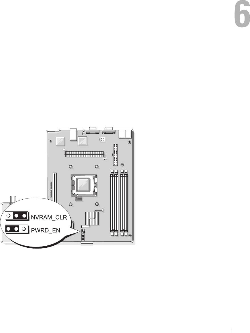
System Board Jumpers
Figure 6-1 shows the location of the configuration jumpers on the system board. Table 6-1 lists the
jumper settings.
Figure 6-1. System Board Jumpers
Jumpers and Connectors 97
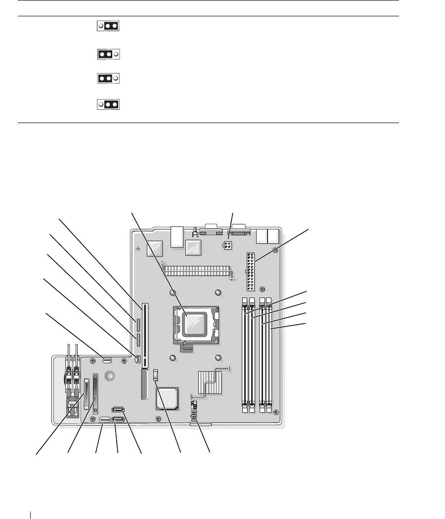
Table 6-1. System Board Jumper Settings
Jumper Setting Description
NVRAM_CLR (default) The configuration settings in NVRAM are retained at system
boot.
The configuration settings in NVRAM are cleared at next
system boot.
PWRD_EN (default) The password feature is enabled.
The password feature is disabled.
System Board Connectors
See Figure 6-2 and Table 6-2 for the location and description of the system board connectors.
Figure 6-2. System Board Connectors
1
2
19
3
18
17
16
4
5
15
6
7
14
13
12 11
10
9 8
98 Jumpers and Connectors

Table 6-2. System Board Connectors
Item Connector Description
1 PROC Processor socket
2 12V power supply connector
3 PWR_CONN power supply connector
4 DIMM 1 Memory module
5 DIMM 3 Memory module
6 DIMM 2 Memory module
7 DIMM 4 Memory module
8 FAN Power connector for the fans
9 BATTERY Connector for the 3.0 V coin battery
10 SATA_0 Connector for the SATA 0 hard drive
11 SATA_1 Connector for the SATA 1 hard drive
12 PCI FAN Connector for the PCI fan
13 FP_CONN1 Control panel interface connector
14 IDE Optical drive interface connector
15 HD_ACT Hard drive activity connector (expansion controller)
16 INTRUSION_SWITCH Connector for the chassis intrusion switch
17 I2C HEADER Remote access controller connector
18 BMC PROG Remote access controller connector
19 RISER_CONN1 Riser card interface connector
Riser Card Connectors
The system is available with either a PCIe riser card or a PCI-X/PCIe riser card. See Figure 6-3 and
Figure 6-4 for the location and description of the expansion-card slots on the two riser cards.
Jumpers and Connectors 99
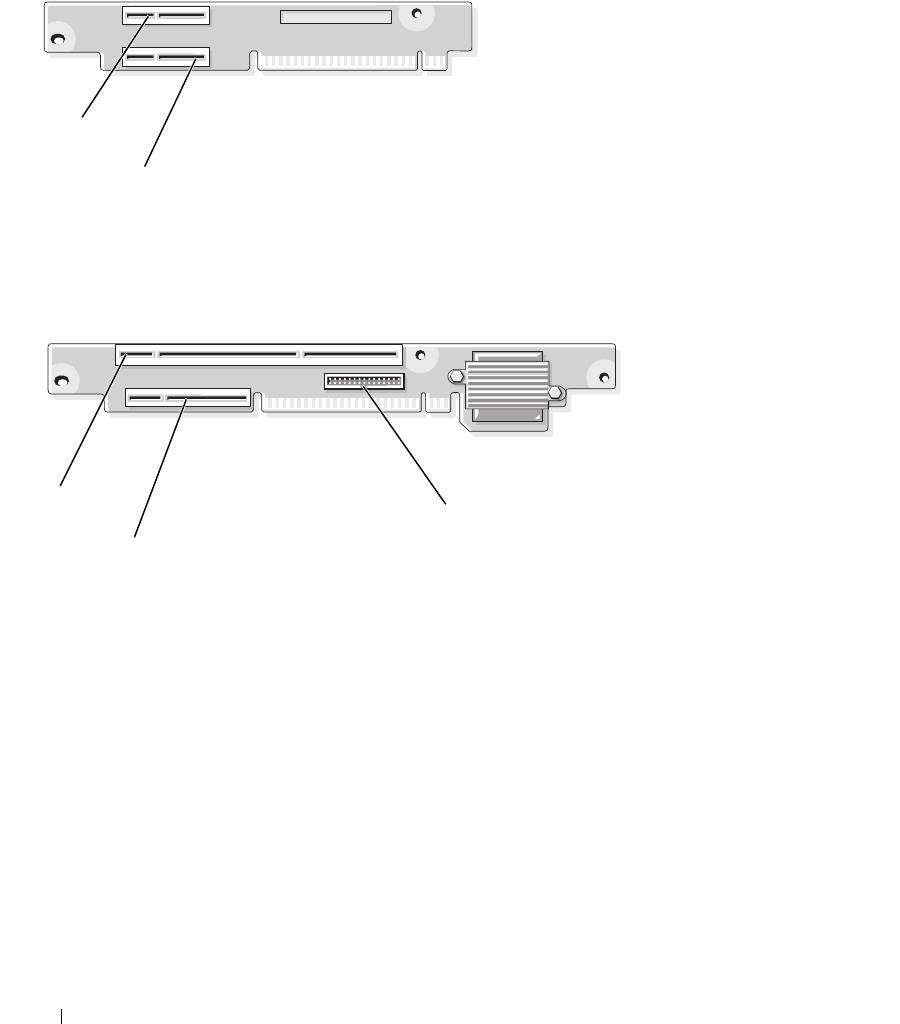
Figure 6-3. PCIe Riser Card Connectors
1
2
1 slot 1, PCIe x4-lane (x8-lane
2 slot 2, PCIe x8-lane
connector)
Figure 6-4. PCI-X/PCIe Riser Card Connectors
1
3
2
1 slot 1, PCI-X 64-bit 133 MHz
2 slot 2, PCIe x8-lane 3 system management
(3.3 V)
100 Jumpers and Connectors
