Dell PowerEdge 860 – страница 4
Инструкция к Компьютеру Dell PowerEdge 860
Оглавление

6
Connect the control panel interface cable to the FP_CONN1 connector on the system board. See
Figure 6-2 for the location of the connector.
7
Connect the optical drive interface cable to the IDE connector on the system board. See Figure 6-2 for
the location of the connector.
8
Close the system. See "Closing the System" on page 47.
Power Supply
The system supports a single nonredundant power supply.
Removing the Power Supply
CAUTION: Only trained service technicians are authorized to remove the system cover and access any of the
components inside the system. Before performing any procedure, see your Product Information Guide for
complete information about safety precautions, working inside the computer and protecting against electrostatic
discharge.
1
Open the system. See "Opening the System" on page 46.
2
Disconnect the following power supply cables:
a
P3 from the hard drive cable harness
b
P2 from system board connector 12V
c
P1 from system board connector PWR_CONN
3
Using a #2 Phillips screwdriver, remove the screw at the front of the power supply that secures the
power supply to the chassis. See Figure 3-13.
4
Slide the power supply forward and lift straight up to remove the power supply from the chassis.
Installing System Components 61
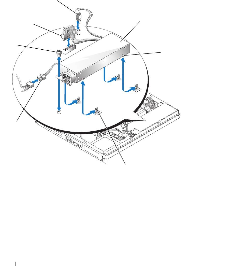
Figure 3-13. Installing and Removing the Power Supply
3
4
2
1
5
7
6
1 screw 2 P1 connector 3 P2 connector
4 power supply 5 pins (4) 6 securing brackets (4)
7 P3 connector
Installing the Power Supply
1
Lower the power supply into the chassis and slide it backward until the four pins on the power supply
are engaged into the securing brackets.
2
Using a #2 Phillips screwdriver, install the screw at the front of the power supply that secures the
power supply to the chassis.
62 Installing System Components

3
Connect the following power supply cables:
a
P3 to the hard drive cable harness
b
P2 to the system board connector 12V
c
P1 to the system board connector PWR_CONN
4
Close the system. See "Closing the System" on page 47.
Expansion Cards
The system is available with an optional PCIe riser card or PCI-X/PCIe riser card. The PCIe riser card
contains two PCIe expansion slots with x8-lane connectors—slot 1 has x4-lane capability and slot 2 has
x8-lane capability. The PCI-X/PCIe riser card provides one PCI-X expansion slot and one PCIe x8-lane
expansion slot. If you are installing a remote access controller card, it must be installed in the upper slot
of a PCI-X/PCIe riser card. See "PCIe Riser Card Connectors" on page 100 for the locations of the
expansion-card slots on the two types of riser cards.
Installing an Expansion Card
CAUTION: Only trained service technicians are authorized to remove the system cover and access any of the
components inside the system. Before performing any procedure, see your Product Information Guide for
complete information about safety precautions, working inside the computer and protecting against electrostatic
discharge.
1
Open the system. See "Opening the System" on page 46.
2
Remove the expansion-card retainer adjacent to the expansion card slots. See Figure 3-14.
3
Slide the expansion-card sliding retainer to the retracted or open position. See Figure 3-15.
4
Remove the filler bracket on the slot you will be using.
NOTE: Keep this bracket if you need to remove the expansion card. Filler brackets must be installed over empty
expansion card slots to maintain Federal Communications Commission (FCC) certification of the system. The
brackets also keep dust and dirt out of the system and aid in proper cooling and airflow inside the system.
5
Insert the expansion card firmly into the expansion-card connector on the riser card until the card is
fully seated.
NOTE: Ensure that the expansion-card bracket is also inserted into the securing slot on the chassis's back
panel.
6
Replace the expansion-card retainer. See Figure 3-14.
7
Slide the expansion-card sliding retainer to the closed position so that it engages the edge of the
expansion card. See Figure 3-15.
8
Connect any internal or external cable(s) to the expansion card.
NOTE: You may need to remove the riser card in order to install certain expansion cards with internal
connectors. See "Riser Card" on page 66.
9
Close the system. See "Closing the System" on page 47.
Installing System Components 63
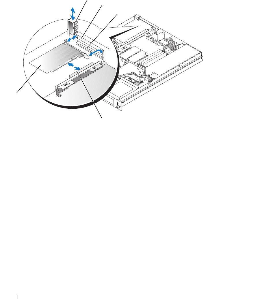
Figure 3-14. Installing and Removing Expansion Cards
1
2
3
5
4
1 expansion-card retainer 2 slot 1 3 slot 2
4 expansion-card connector (on
5 expansion card
riser card)
64 Installing System Components
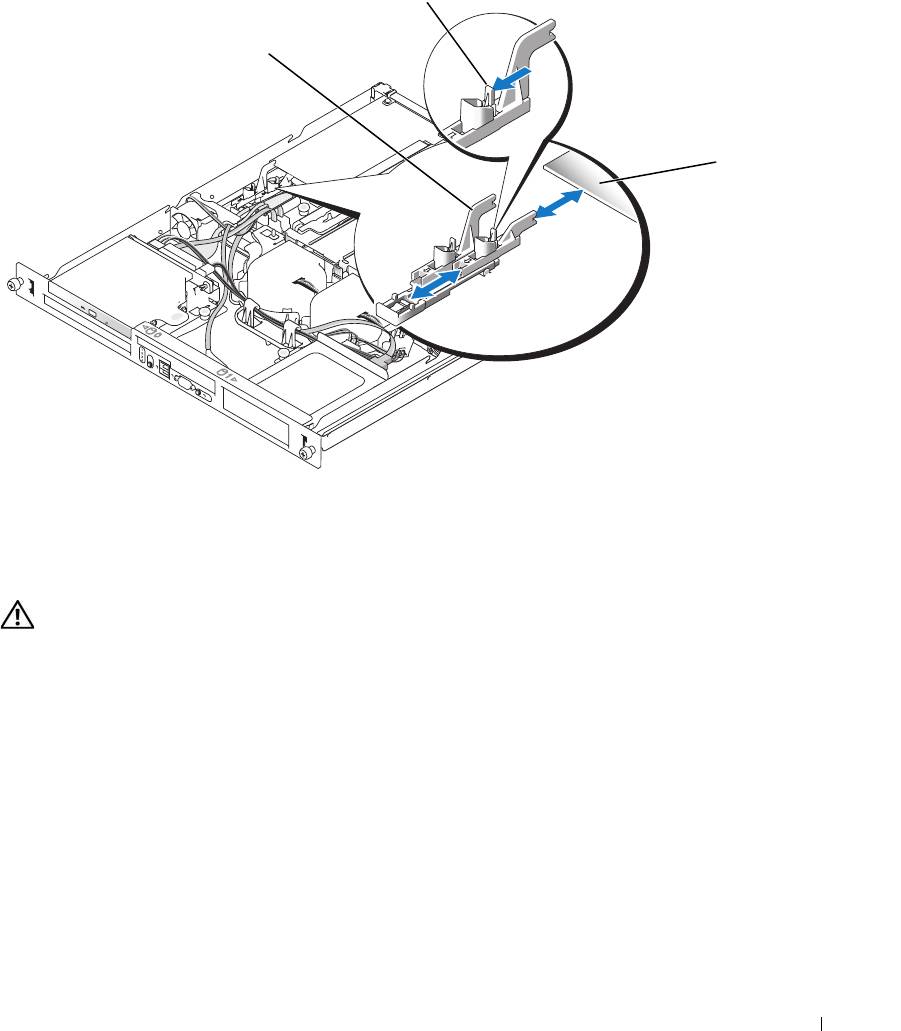
Figure 3-15. Opening and Closing the Expansion-Card Sliding Retainer
2
1
3
1 expansion-card sliding
2 release tab 3 expansion card
retainer
Removing an Expansion Card
CAUTION: Only trained service technicians are authorized to remove the system cover and access any of the
components inside the system. Before performing any procedure, see your Product Information Guide for
complete information about safety precautions, working inside the computer and protecting against electrostatic
discharge.
1
Open the system. See "Opening the System" on page 46.
2
Disconnect any internal or external cable(s) that are connected to the expansion card.
3
Lift the expansion-card retainer adjacent to the PCI slots. See Figure 3-14.
4
Slide the expansion-card sliding retainer to the retracted or open position. See Figure 3-15.
5
Grip the edges of the expansion card with the fingers of both hands and carefully work the card out of
the expansion-card connector.
Installing System Components 65
6
If you are permanently removing the card, replace the metal filler bracket over the empty card-slot
opening.
NOTE: Filler brackets must be installed over empty expansion-card slots to maintain FCC certification of the
system. The brackets also keep dust and dirt out of the system and aid in proper cooling and airflow inside the
system.
7
Replace the expansion-card retainer.
8
Close the system. See "Closing the System" on page 47.
Riser Card
The riser card provides two expansion-card slots. See "Expansion Cards" on page 63 for detailed
information on the expansion-card slots.
Removing the Riser Card
CAUTION: Only trained service technicians are authorized to remove the system cover and access any of the
components inside the system. Before performing any procedure, see your Product Information Guide for
complete information about safety precautions, working inside the computer and protecting against electrostatic
discharge.
1
Open the system. See "Opening the System" on page 46.
2
Remove any expansion card(s). See "Removing an Expansion Card" on page 65.
3
Using a #2 Phillips screwdriver, remove the two screws that secure the riser card to the chassis. See
Figure 3-16.
4
Lift the riser card straight up and remove the riser card from the system.
66 Installing System Components
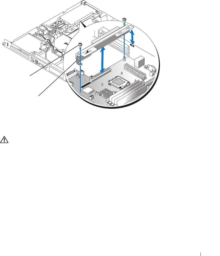
Figure 3-16. Installing and Removing the Riser Card
1
2
1 screws (2) 2 riser card
Installing the Riser Card
CAUTION: Only trained service technicians are authorized to remove the system cover and access any of the
components inside the system. Before performing any procedure, see your Product Information Guide for
complete information about safety precautions, working inside the computer and protecting against electrostatic
discharge.
1
Insert the riser card firmly into the riser card connector on the system board until the riser card is fully
seated.
2
Using a #2 Phillips screwdriver, install the two screws that secure the riser card to the system board.
3
Install any expansion card(s). See "Installing an Expansion Card" on page 63.
4
Close the system. See "Closing the System" on page 47.
System Memory
The four memory module sockets are located on the system board adjacent to the power supply and can
accommodate 512 MB to 8 GB of unbuffered ECC PC-3200 (DDR2 533 or DDR 667) memory. See
Figure 6-2
for the location of the memory module sockets.
Installing System Components 67

You can upgrade the system memory by installing combinations of 512-MB, 1-GB, and 2-GB unbuffered
memory modules. If you receive an error message stating that maximum memory has been exceeded, see
"System Messages" on page 15 for more information. You can purchase memory upgrade kits from Dell.
NOTE: The memory modules must be PC-3200 compliant.
Memory Module Installation Guidelines
The memory module sockets are arranged in banks (1 and 2) on two channels (A and B).
The memory module banks are identified as follows:
Bank 1: DIMM1_A and DIMM1_B
Bank 2: DIMM2_A and DIMM2_B
The memory module banks must be installed in identical pairs in configurations that have more than
one memory module. For example, if socket DIMM1_A contains a 512-MB memory module, then the
second memory module to be installed must be a 512-MB memory module in socket DIMM1_B.
Table 3-1 shows examples of different memory configurations, based on the following guidelines:
• The minimum memory configuration is 512 MB.
• If only one memory module is installed, it must be installed in the DIMM1_A socket.
• A bank must contain identical memory modules.
• Install the memory modules in bank 1 (DIMM1_
x
) before installing memory modules in bank 2
(DIMM2_
x
).
• Installing three memory modules is not supported.
Table 3-1. Sample Memory Module Configurations
Total Memory DIMM1_A DIMM2_A DIMM1_B DIMM2_B
512 MB 512 MB None None None
1 GB 512 MB None 512 MB None
1 GB 1 GB None None None
2 GB 512 MB 512 MB 512 MB 512 MB
2 GB 1 GB None 1 GB None
3 GB 1 GB 512 MB 1 GB 512 MB
4 GB 1 GB 1 GB 1 GB 1 GB
4 GB 2 GB None 2 GB None
5 GB 2 GB 512 MB 2 GB 512 MB
6 GB 2 GB 1 GB 2 GB 1 GB
8 GB 2 GB 2 GB 2 GB 2 GB
68 Installing System Components

Installing Memory Modules
CAUTION: Only trained service technicians are authorized to remove the system cover and access any of the
components inside the system. Before performing any procedure, see your Product Information Guide for
complete information about safety precautions, working inside the computer and protecting against electrostatic
discharge.
1
Open the system. See "Opening the System" on page 46.
2
Locate the memory module sockets. See Figure 6-2.
3
Press the ejectors on the memory module socket down and out, as shown in Figure 3-17, to allow the
memory module to be inserted into the socket.
4
Align the memory module's edge connector with the alignment keys of the memory module socket,
and insert the memory module in the socket.
NOTE: The memory module socket has two alignment keys that allow you to install the memory module in the
socket in only one way.
5
Press down on the memory module with your thumbs while pulling up on the ejectors with your index
fingers to lock the memory module into the socket.
When the memory module is properly seated in the socket, the ejectors on the memory module socket
align with the ejectors on the other sockets that have memory modules installed.
6
Repeat step 2 through step 5 of this procedure to install the remaining memory modules. See Table 3-1
for valid memory configurations.
7
Close the system. See "Closing the System" on page 47.
8
(Optional) Press <F2> to enter the System Setup program, and check the
System Memory
setting on
the main
System Setup
screen.
The system should have already changed the value to reflect the newly installed memory.
9
If the value is incorrect, one or more of the memory modules may not be installed properly. Repeat
step 1 through step 8 of this procedure, checking to ensure that the memory modules are firmly seated
in their sockets.
10
Run the system memory test in the system diagnostics. See "Running the System Diagnostics" on
page 93.
Installing System Components 69
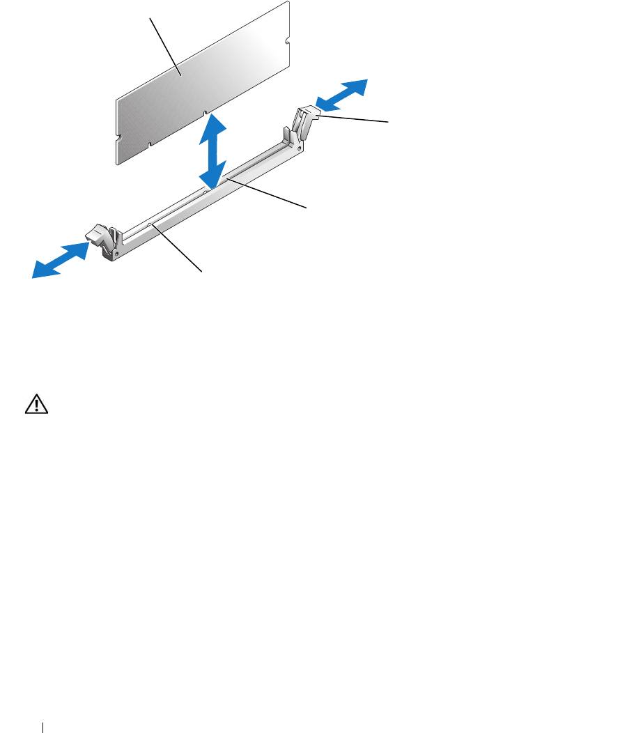
Figure 3-17. Installing and Removing a Memory Module
1
2
3
4
1 memory module 2 memory module socket
3 socket
ejectors (2)
4 alignment keys (2)
Removing Memory Modules
CAUTION: Only trained service technicians are authorized to remove the system cover and access any of the
components inside the system. Before performing any procedure, see your Product Information Guide for
complete information about safety precautions, working inside the computer and protecting against electrostatic
discharge.
1
Open the system. See "Opening the System" on page 46.
2
Locate the memory module sockets. See Figure 6-2.
3
Press down and out on the ejectors on each end of the socket until the memory module pops out of the
socket. See Figure 3-17.
4
Close the system. See "Closing the System" on page 47.
Processor
You can upgrade the processor to take advantage of future options in speed and functionality. The
processor and its associated internal cache memory are contained in a land grid array (LGA) package that
is installed in a ZIF socket on the system board.
70 Installing System Components
Replacing the Processor
CAUTION: Only trained service technicians are authorized to remove the system cover and access any of the
components inside the system. Before performing any procedure, see your Product Information Guide for
complete information about safety precautions, working inside the computer and protecting against electrostatic
discharge.
1
Open the system. See "Opening the System" on page 46.
NOTICE: Never remove the heat sink from a processor unless you intend to remove the processor. The heat sink is
necessary to maintain proper thermal conditions.
NOTE: When you remove the heat sink, the possibility exists that the processor might adhere to the heat sink and
be removed from the socket. It is recommended that you remove the heat sink while the processor is still warm.
2
Remove the cooling shroud. See "Removing the Cooling Shroud" on page 47.
3
Using a #2 Phillips screwdriver, loosen the four captive screws that secure the heat sink to the system
board. See Figure 3-18.
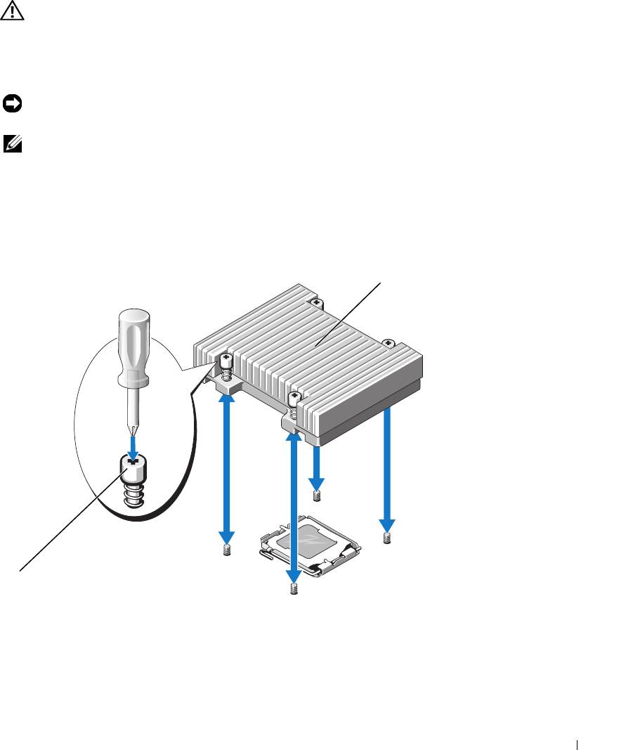
Figure 3-18. Installing and Removing the Heat Sink
2
1
1 captive screws (4) 2 heat sink
4
Wait 30 seconds for the heat sink to loosen from the processor.
Installing System Components 71
5
If the heat sink has not separated from the processor, carefully rotate the heat sink in a clockwise, then
counterclockwise, direction until it releases from the processor. Do not pry the heat sink off of the
processor.
6
Lift the heat sink off of the processor and set the heat sink aside.
7
Press down on the processor socket release lever, then pull the release lever upward to the fully open
position. See Figure 3-19.
8
Open the processor cover. See Figure 3-19.
9
Lift the processor vertically out of the socket. Leave the processor cover and release lever in the open
position so that the socket is ready for the new processor. See Figure 3-19.
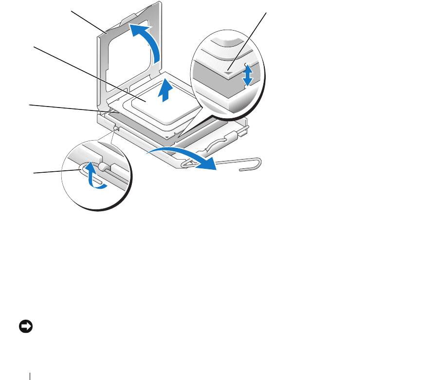
Figure 3-19. Installing and Removing the Processor
4
5
3
2
1
1 processor socket release
2 processor socket 3 processor
lever
4 processor cover 5 pin-1 locators
10
Unpack the new processor.
11
Ensure that the processor socket release lever is in the fully open position.
12
Align the pin 1 corners of the processor and socket. See Figure 3-19.
NOTICE: You must position the processor correctly in the socket to avoid damaging the processor and the system
board when you turn on the system. Be careful not to touch or bend the pins on the socket.
72 Installing System Components
13
Set the processor lightly in the socket and ensure that the processor is level in the socket. When the
processor is positioned correctly, press it gently to seat it in the socket.
14
Close the processor cover.
15
Rotate the release lever back down until it snaps into place, securing the processor cover.
16
Install the heat sink.
a
Using a clean lint-free cloth, remove the existing thermal grease from the heat sink.
NOTE: Use the heat sink that you removed earlier in this procedure.
b
Apply thermal grease evenly to the top of the processor.
c
Place the heat sink onto the processor. See Figure 3-18.
d
Using a #2 Phillips screwdriver, tighten in a diagonal pattern the four captive screws that secure
the heat sink to the system board. See Figure 3-18.
17
Install the cooling shroud. See "Installing the Cooling Shroud" on page 48.
18
Close the system. See "Closing the System" on page 47.
As the system boots, it detects the presence of the new processor and automatically changes the system
configuration information in the System Setup program.
19
Press <F2> to enter the System Setup program, and check that the processor information
matches the
new system configuration.
See "Using the System Setup Program" on page 29.
20
Run the system diagnostics to verify that the new processor operates correctly.
See "Running the System Diagnostics" on page 93 for information about running the diagnostics and
troubleshooting processor problems.
Control Panel Assembly (Service-Only Procedure)
Removing the Control Panel Assembly
CAUTION: Only trained service technicians are authorized to remove the system cover and access any of the
components inside the system. Before performing any procedure, see your Product Information Guide for
complete information about safety precautions, working inside the computer and protecting against electrostatic
discharge.
1
Open the system. See "Opening the System" on page 46.
2
Disconnect the control panel cables. See Figure 3-20.
3
Using a #2 Phillips screwdriver, remove the two screws that secure the control panel assembly to the
chassis. See Figure 3-20.
4
Carefully lift the back of the control panel assembly to clear the chassis mounting studs, and remove
the assembly from the system.
Installing System Components 73
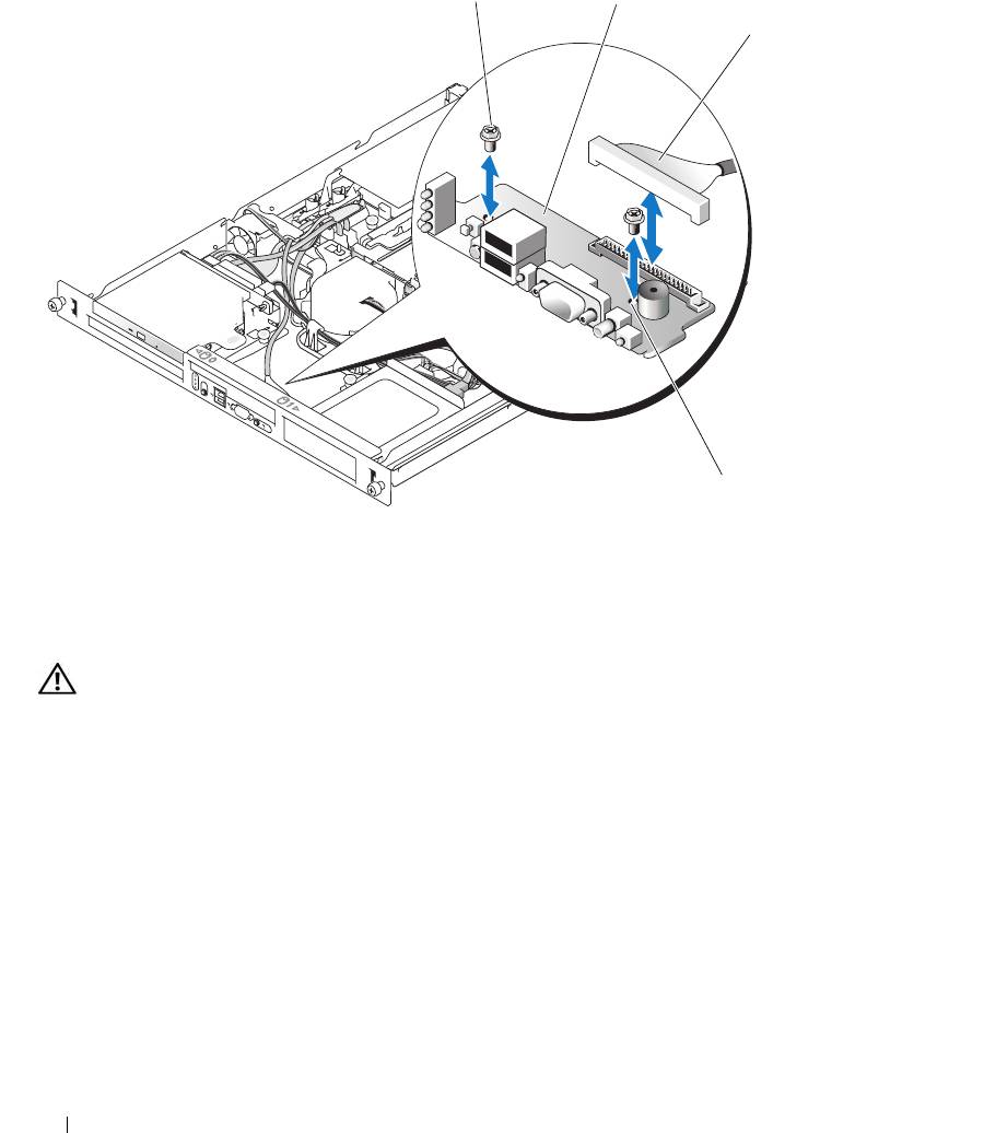
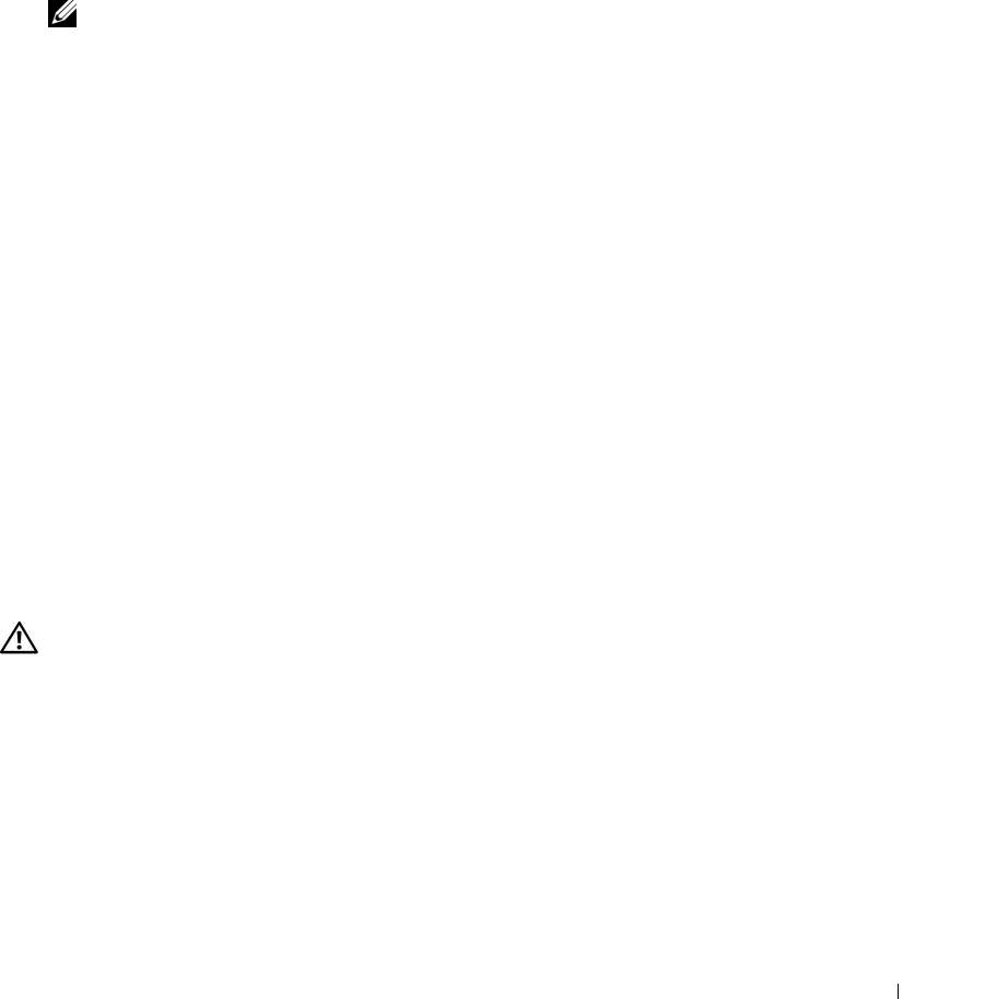
Figure 3-20. Installing and Removing the Control Panel Assembly
1
2
3
4
1 control panel assembly 2 screws (2) 3 cables
4 mounting holes (2)
Installing the Control Panel Assembly
CAUTION: Only trained service technicians are authorized to remove the system cover and access any of the
components inside the system. Before performing any procedure, see your Product Information Guide for
complete information about safety precautions, working inside the computer and protecting against electrostatic
discharge.
1
Align the control panel assembly’s mounting holes with the chassis mounting holes. See Figure 3-20.
2
Using a #2 Phillips screwdriver, install the two screws that secure the control panel assembly to the
chassis. See Figure 3-20.
3
Connect the control panel cables. See Figure 3-20.
4
Close the system. See "Closing the System" on page 47.
74 Installing System Components

System Board (Service-Only Procedure)
The system board and system board tray are removed and replaced as a single assembly.
Removing the System Board Assembly
CAUTION: Only trained service technicians are authorized to remove the system cover and access any of the
components inside the system. Before performing any procedure, see your Product Information Guide for
complete information about safety precautions, working inside the computer and protecting against electrostatic
discharge.
1
Open the system. See "Opening the System" on page 46.
2
Remove the cooling shroud. See "Removing the Cooling Shroud" on page 47.
3
Remove the heat sink and processor. See "Replacing the Processor" on page 71.
4
Remove the memory modules. See "Removing Memory Modules" on page 70.
NOTE: As you remove the memory modules, record the memory module socket locations to ensure proper
installation.
5
If applicable, disconnect the optical drive interface cable from the IDE connector on the system board.
See Figure 6-2.
6
Disconnect the control-panel interface cable from the FP_CONN1 connector on the system board.
See Figure 6-2.
7
Disconnect the hard-drive interface cables:
a
If a SAS controller is installed, disconnect the interface cable from the controller card.
b
If the system hard drives are connected to the integrated controller, disconnect the interface cables
from the SATA_0 and SATA_1 connectors on the board. See Figure 6-2.
8
Remove all PCI expansion cards installed on the riser card. See "Removing an Expansion Card" on
page 65.
9
Remove the riser card. See "Removing the Riser Card" on page 66.
10
Disconnect the chassis intrusion cable from the INTRUSION_SWITCH connector on the system
board.
11
Disconnect the two power cables from the 12V and PWR_CONN connectors on the system board. See
Figure 6-2.
12
Pull up on the plunger that secures the system board tray to the chassis floor. See Figure 3-21.
13
Using the tab on the system board tray, slide the system board forward (toward the front of the system)
and lift the assembly up and out of the chassis. See Figure 3-21.
14
Lay the system board tray down on a smooth, nonconductive work surface.
Installing System Components 75
Figure 3-21. Installing and Removing the System Board
1
3
2
1 plunger 2 system board 3 system board tray
Installing the System Board Assembly
CAUTION: Only trained service technicians are authorized to remove the system cover and access any of the
components inside the system. Before performing any procedure, see your Product Information Guide for
complete information about safety precautions, working inside the computer and protecting against electrostatic
discharge.
1
Unpack the new system board assembly.
2
Align the system board tray so that the tabs on the chassis floor slide into the notches in the system
board tray.
3
Slide the system board tray backward until it stops.
4
Press down on the plunger that secures the system board tray to the chassis. See Figure 3-21.
76 Installing System Components

5
Connect the two power cables to the 12V and PWR_CONN connectors on the system board. See
Figure 6-2.
6
Connect the chassis intrusion cable to the INTRUSION_SWITCH connector on the system board.
7
Install the riser card. See "Installing the Riser Card" on page 67.
8
Using a #2 Phillips screwdriver, tighten the two screws that secure the riser card to the system board.
9
Install any PCI expansion cards that you removed. See "Installing an Expansion Card" on page 63.
10
Connect the hard-drive interface cables:
a
If you installed a SAS controller, reconnect the interface cable to the controller card.
b
If your configuration uses the integrated controller, reconnect the hard drive 0 interface cable to
the SATA_0 connector and the hard drive 1 interface cable to the SATA_1 connector on the
system board. See Figure 6-2 for the location of the SATA connectors.
11
Install the processor and heat sink. See "Replacing the Processor" on page 71.
12
Install the memory modules. See "Installing Memory Modules" on page 69.
NOTE: Install the memory modules as noted in step 3 of the procedure in "Removing the System Board
Assembly" on page 75.
13
Connect the control-panel interface cable to the FP_CONN1 connector on the system board. See
Figure 6-2 for the location of the FP_CONN1 connector.
14
If applicable, connect the optical drive interface cable to the IDE connector on the system card. See
Figure 6-2 for the location of the IDE connector.
15
Install the cooling shroud. See "Installing the Cooling Shroud" on page 48.
16
Close the system. See "Closing the System" on page 47.
Installing System Components 77

78 Installing System Components
Troubleshooting Your System
Safety First—For You and Your System
To perform certain procedures in this document, you must remove the system cover and work inside the
system. While working inside the system, do not attempt to service the system except as explained in
this guide and elsewhere in your system documentation.
CAUTION: Only trained service technicians are authorized to remove the system cover and access any of
the components inside the system. Before performing any procedure, see your Product Information Guide for
complete information about safety precautions, working inside the computer and protecting against
electrostatic discharge.
Start-Up Routine
Look and listen during the system's start-up routine for the indications described in Table 4-1.
Table 4-1. Start-Up Routine Indications
Look/listen for: Action
An error message displayed on the
See "System Messages" on page 15.
monitor.
System status and diagnostic indicators See "Front-Panel Features and Indicators" on page 11 and
"Diagnostics Indicator Codes" on page 22.
Alert messages from the systems
See the systems management software documentation.
management software.
The monitor's power indicator. See "Troubleshooting the Video Subsystem" on page 81.
The keyboard indicators. See "Troubleshooting the Keyboard" on page 81.
The USB diskette drive activity indicator. See "Troubleshooting a USB Device" on page 83.
The USB CD drive activity indicator. See "Troubleshooting a USB Device" on page 83.
The optical drive activity indicator. See "Troubleshooting an Optical Drive" on page 89.
The hard-drive activity indicator. See "Troubleshooting a Hard Drive" on page 90.
An unfamiliar constant scraping or
See
"Getting Help
" on page 103
.
grinding sound when you access a drive.
Troubleshooting Your System 79

Checking the Equipment
This section provides troubleshooting procedures for external devices attached to the system, such as the
monitor, keyboard, or mouse. Before you perform any of the procedures, see "Troubleshooting External
Connections" on page 81.
Troubleshooting IRQ Assignment Conflicts
Most PCI devices can share an IRQ with another device, but they cannot use an IRQ simultaneously. To
avoid this type of conflict, see the documentation for each PCI device for specific IRQ requirements.
Table 4-2 lists the IRQ assignments.
Table 4-2. IRQ Assignment Defaults
IRQ Line Assignment
IRQ0 System timer
IRQ1 Keyboard controller
IRQ2 Interrupt controller 1 to enable IRQ8 through IRQ15
IRQ3 Available
IRQ4 Serial port 1 (COM1 and COM3)
IRQ5 Available
IRQ6 Available
IRQ7 Available
IRQ8 Real-time clock
IRQ9 ACPI functions (used for power management)
IRQ10 Available
IRQ11 Available
IRQ12 PS/2 mouse port (available if the mouse is disabled through the System Setup
program)
IRQ13 Math coprocessor
IRQ14 IDE optical drive controller (available if IDE CDROM controller is disabled through
the System Setup program)
IRQ15 Reserved (available if IDE CDROM controller is disabled through the System Setup
program)
80 Troubleshooting Your System
