Dell PowerEdge 860 – страница 3
Инструкция к Компьютеру Dell PowerEdge 860
Оглавление

• Control of system functions including power on and off
• Support is independent of the system’s power or operating state
• Provides text console redirection for system setup, text-based utilities, and operating system consoles
NOTE: To remotely access the BMC through the integrated NIC, you must connect the network connection to
integrated NIC1.
For additional information on using BMC, see the documentation for the BMC and systems management
applications.
Entering the BMC Setup Module
1
Turn on or restart your system.
2
Press <
Ctrl-E
> when prompted after POST.
If your operating system begins to load before you press <
Crtl-E
>, allow the system to finish
booting, and then restart your system and try again.
BMC Setup Module Options
For information about the BMC Setup Module options and how to configure the emergency management
port (EMP), see the
BMC User’s Guide
.
Using the System Setup Program 41

42 Using the System Setup Program

Installing System Components
This section describes how to install the following system components:
• Cooling shroud
• System battery
• Optical drive
• Hard drives
• Fan assembly
• Optional PCI fan
• Power supply
• Expansion cards
• Riser card
• System memory
• Processor
• Control panel
• System board
Recommended Tools
You may need the following items to perform the procedures in this section:
• Key to the system keylock
• Wrist grounding strap
• #2 Phillips screwdriver
Inside the System
In Figure 3-1, the bezel and system cover are removed to provide an interior view of the system.
Installing System Components 43
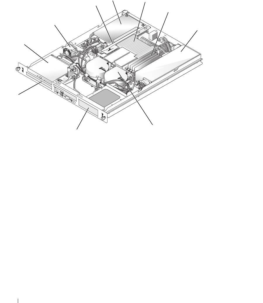
Figure 3-1. Inside the System
4
5
3
6
2
7
1
10
8
9
1 optical drive (optional) 2 PCI fan 3 riser card
4 PCI expansion card (optional) 5 processor and heat sink 6 memory modules (4)
7 power supply 8 processor fan module 9 hard drive 1
10 hard drive 0
The system board holds the system's control circuitry and other electronic components. The processor
and memory are installed directly on the system board. Using a riser card, the system can accommodate
two expansion cards. The peripheral bays provide space for up to two hard drives and an optional optical
drive. Power is supplied to the system board and drives through one nonredundant power supply.
Opening and Closing the System
The system is enclosed by an optional bezel and cover. To upgrade or troubleshoot the system, remove
the bezel and cover.
44 Installing System Components
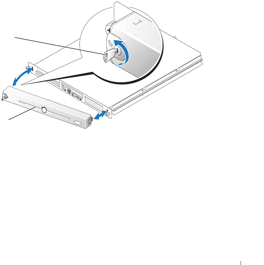
Removing the Bezel
1
Unlock the bezel. See Figure 3-2.
2
Unlatch the left end of the bezel and rotate it away from the front panel.
3
Unhook the right end of the bezel and pull the bezel away from the system.
Figure 3-2. Installing and Removing the Optional Bezel
1
2
1 key lock 2 bezel
Installing the Bezel
1
Hook the right end of the bezel into the bezel slot on the right side of the system front plate
2
Rotate the other end of the bezel toward the front panel and press the bezel onto the panel to engage
the latch.
3
Lock the bezel.
Installing System Components 45
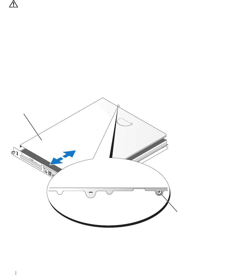
Opening the System
CAUTION: Only trained service technicians are authorized to remove the system cover and access any of the
components inside the system. Before performing any procedure, see your Product Information Guide for
complete information about safety precautions, working inside the computer and protecting against electrostatic
discharge.
1
Turn off the system and attached peripherals, and disconnect the system from the electrical outlet and
peripherals.
2
Extend the system out of the rack to the locked position. If the system is installed on static rails,
remove the system from the rack and place it on a work surface.
3
To remove the system cover, loosen the thumbscrew at the back of the system. See Figure 3-3.
4
Slide the cover backward about 1.3 cm (0.5 inch), and grasp the cover on both sides.
5
Carefully lift the cover away from the system.
Figure 3-3. Installing and Removing the System Cover
1
2
1 system cover 2 thumbscrew
46 Installing System Components

Closing the System
1
Ensure that you did not leave tools or parts inside the system.
2
Place the cover over the sides of the chassis, and slide the cover forward.
3
Tighten the thumbscrew at the back of the system to secure the cover. See Figure 3-3.
4
Replace the system in the rack, and reconnect the peripheral cables.
5
Reconnect the system to the electrical outlet, and turn on the system.
Cooling Shroud
The cooling shroud covers the processor and system battery and provides air flow to these components
and the system memory.
Removing the Cooling Shroud
CAUTION: Only trained service technicians are authorized to remove the system cover and access any of the
components inside the system. Before performing any procedure, see your Product Information Guide for
complete information about safety precautions, working inside the computer and protecting against electrostatic
discharge.
1
Open the system. See "Opening the System" on page 46.
2
While grasping the cooling shroud, press the release latch and lift the shroud away from the fan
assembly. See Figure 3-4.
3
Remove the cooling shroud.
Installing System Components 47
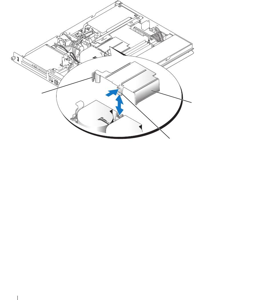
Figure 3-4. Installing and Removing the Cooling Shroud
1
3
2
1 tab 2 release latch 3 cooling shroud
Installing the Cooling Shroud
1
Insert the tab on the side of the cooling shroud and the release latch into the fan assembly. See
Figure 3-4.
2
Push the cooling shroud down until the release latch snaps into place, securing the shroud to the fan
assembly.
3
Close the system. See "Closing the System" on page 47.
48 Installing System Components
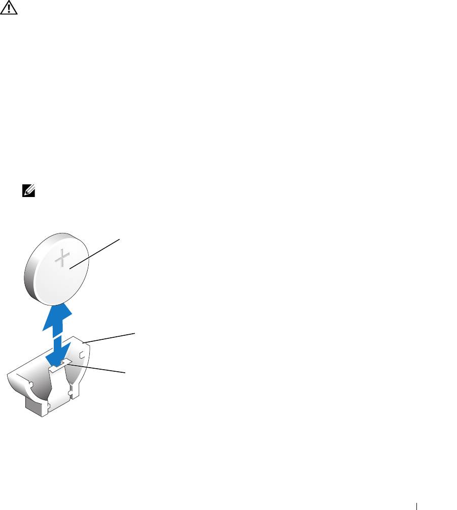
System Battery
Replacing the System Battery
CAUTION: Only trained service technicians are authorized to remove the system cover and access any of the
components inside the system. Before performing any procedure, see your Product Information Guide for
complete information about safety precautions, working inside the computer and protecting against electrostatic
discharge.
1
Enter the System Setup program and, if possible, make a printed copy of the System Setup screens.
See "Using the System Setup Program" on page 29.
2
Open the system. See "Opening the System" on page 46.
3
Remove the cooling shroud. See "Removing the Cooling Shroud" on page 47.
4
Remove the riser card. See "Removing the Riser Card" on page 66.
5
Locate the battery on the system board. See Figure 6-2 for the battery location.
6
Grasp the battery with your fingers and pull it out of the battery socket. See Figure 3-5.
7
Push the new battery into the battery socket as shown in Figure 3-5.
NOTE: The side of the battery labeled "+" must face toward the open side of the battery socket.
Figure 3-5. Replacing the Battery
1
2
3
1 battery 2 battery socket 3 retention tab
Installing System Components 49

8
Reinstall the riser card. See "Installing the Riser Card" on page 67.
9
Install the cooling shroud. See "Installing the Cooling Shroud" on page 48.
10
Close the system. See "Closing the System" on page 47.
11
Enter the System Setup program to confirm that the battery operates properly.
12
From the main screen, select
System Time
to enter the correct time and date.
Also, re-enter any system configuration information that is no longer displayed on the System Setup
screens, and then exit the System Setup program.
13
To test the newly installed battery, see "Troubleshooting the System Battery" on page 86.
Optical Drive
The optional optical drive is mounted in a bracket using two alignment pins and a spring clip on top of
hard drive 0. An interposer card is connected to the back of the drive which allows the drive to be
connected to the IDE connector on the system board.
Removing the Optical Drive
CAUTION: Only trained service technicians are authorized to remove the system cover and access any of the
components inside the system. Before performing any procedure, see your Product Information Guide for
complete information about safety precautions, working inside the computer and protecting against electrostatic
discharge.
1
Open the system. See "Opening the System" on page 46.
2
Disconnect the power and interface cables from the optical drive's interposer card.
3
Pull the two captive fasteners that secure the interposer card to the hard drive 0 carrier. See Figure 3-6.
4
Disconnect the interposer card from the optical drive.
5
Press the bracket release lever that secures the optical drive to the hard drive 0 carrier. See Figure 3-6.
6
Lift and tilt the optical drive up and out of the bracket as shown in Figure 3-6.
50 Installing System Components
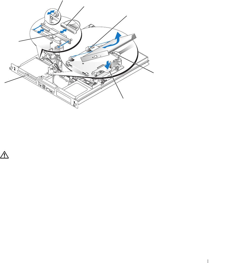
Figure 3-6. Removing and Installing the Optional Optical Drive
2
3
4
1
5
7
6
1 interposer board 2 captive fasteners (2) 3 interface cable
4 retaining pins (4) 5 mounting holes (4) 6 bracket release lever
7 hard drive 0
Installing the Optical Drive
CAUTION: Only trained service technicians are authorized to remove the system cover and access any of the
components inside the system. Before performing any procedure, see your Product Information Guide for
complete information about safety precautions, working inside the computer and protecting against electrostatic
discharge.
1
Align the optical drive's mounting holes with the retaining pins on the hard drive 0 bracket. See
Figure 3-6.
2
Rotate the drive downward until it snaps into place.
3
Connect the interposer card to the optical drive.
Push the plungers into the captive fastener barrels until they snap into place.
4
Connect the interface and power cables to the optical drive's interposer card.
5
Close the system. See "Closing the System" on page 47.
Installing System Components 51
Configuring the Boot Drive
The drive or device from which the system boots is determined by the boot order specified in the System
Setup program. See "Using the System Setup Program" on page 29. To boot the system from a hard drive
or drive array, the drive(s) must be connected to the appropriate controller:
• For systems using the integrated hard-drive controller, the master drive (drive 0) must be connected to
the SATA_PORT_0 connector on the system board. To identify system board connectors, see
Figure 6-2.
• For systems with a SAS controller installed, the hard drive must be connected to the SAS controller
card. See the documentation that accompanied the controller card.
• To boot from a SAS RAID array, the drive must be connected to the RAID controller card. See the
documentation that accompanied the controller card.
Hard Drives
Your system contains up to two non-hot-pluggable SATA or SAS hard drives. If your system contains SAS
hard drives, they must be connected to a SAS controller card. The cables for hard drive 1 are routed
through a cable clamp mounted to the chassis.
Removing a Hard Drive
The procedures for removing and installing SATA or SAS hard drives are the same.
CAUTION: Only trained service technicians are authorized to remove the system cover and access any of the
components inside the system. Before performing any procedure, see your Product Information Guide for
complete information about safety precautions, working inside the computer and protecting against electrostatic
discharge.
1
Open the system. See "Opening the System" on page 46.
2
If applicable, remove the optical drive.
Remove the optical drive if you are removing hard drive 0. See "Removing the Optical Drive" on
page 50.
3
Disconnect the power and interface cables from the hard drive.
The interface cables for SATA hard drives are connected to the system board. See Figure 6-2 for the
location of the system board connectors.
The interface cables for SAS hard drives are connected to a controller card.
4
Pull up on the plunger that secures the hard-drive carrier to the chassis. See Figure 3-7.
5
Slide the hard-drive carrier backward and lift the carrier out of the chassis.
52 Installing System Components
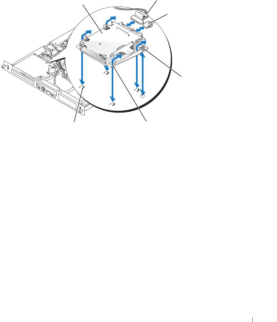
Figure 3-7. Removing the HDD0 Hard-Drive Carrier
1
4
1 HDD0 hard-drive carrier 2 interface cable 3 power cable
4 plunger 5 notches (4) 6 tabs (4)
Installing System Components 53
2
3
5
6
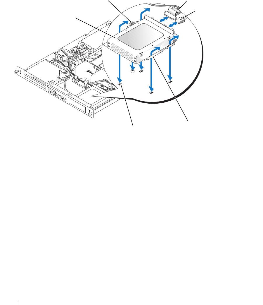
Figure 3-8. Removing the HDD1 Hard-Drive Carrier
2
3
4
1
5
6
1 HDD1 hard-drive carrier 2 plunger 3 interface cable
4 power cable 5 notches (4) 6 tabs (4)
6
Using a #2 Phillips screwdriver, remove the four screws that secure the hard drive to the carrier and
remove the drive from the carrier. See Figure 3-10.
54 Installing System Components
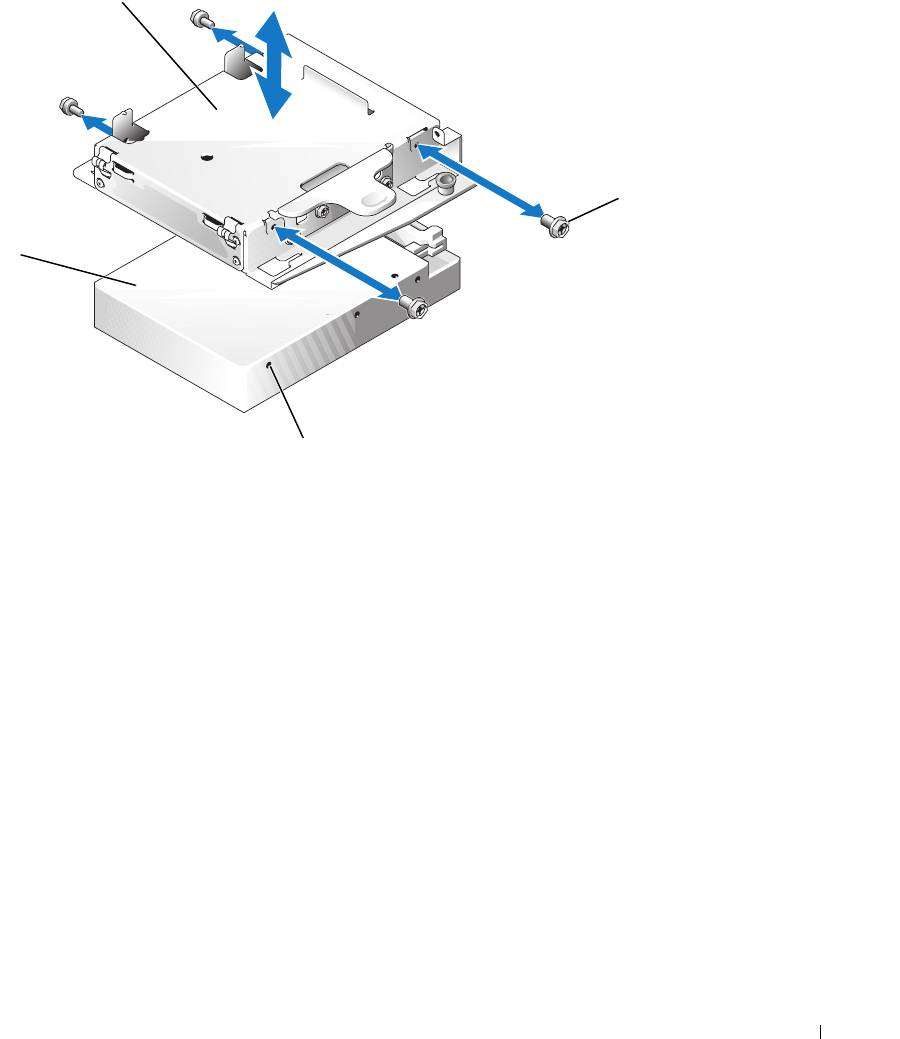
Figure 3-9. Removing the Hard Drive From the HDD0 Drive Carrier
1
2
4
3
1 HDD0 hard-drive carrier 2 screws (4) 3 mounting holes (4)
4 hard drive
Installing System Components 55
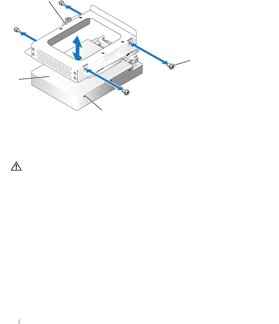
Figure 3-10. Removing the Hard Drive From the HDD1 Drive Carrier
1
2
4
3
1 HDD1 hard-drive carrier 2 screws (4) 3 mounting holes (4)
4 hard drive
Installing a Hard Drive
CAUTION: Only trained service technicians are authorized to remove the system cover and access any of the
components inside the system. Before performing any procedure, see your Product Information Guide for
complete information about safety precautions, working inside the computer and protecting against electrostatic
discharge.
1
Align the hard-drive mounting holes with the holes in the drive carrier.
2
Using a #2 Phillips screwdriver, install the four screws that secure the hard drive to the carrier. See
Figure 3-10.
3
Align the hard-drive carrier so that the tabs on the chassis slide into the notches in the carrier. See
Figure 3-7.
4
Slide the carrier forward until it stops.
5
Press down on the plunger to secure the hard-drive carrier to the chassis. See Figure 3-7 and Figure 3-8.
6
Connect the power and interface cables to the new drive:
• If no SAS controller card is present, attach SATA interface cables to the hard drives and the SATA
connectors on the system board. Connect hard drive 0 to the SATA_0 connector and hard drive 1
to the SATA_1 connector. See Figure 6-2 for the location of the SATA connectors.
56 Installing System Components

• If a SAS controller card is present, attach the HDD0 cable from the SAS controller to hard drive 0
and attach the HDD1 cable to hard drive 1. See the controller card documentation for further
information.
7
Install the CD drive.
Install the CD drive if you are removing hard drive 0. See "Installing the Optical Drive" on page 51.
8
Close the system. See "Closing the System" on page 47.
Installing a SAS Controller Card
See "Installing an Expansion Card" on page 63 for general instructions about installing the controller
card. See the controller card documentation for specific information on installing and configuring the
card.
NOTICE: If your SAS controller has an external storage connector, you must install the optional PCI fan assembly
in your system to maintain the proper cooling environment. Failure to install the fan assembly could result in the
system overheating and shutting down unexpectedly. See "Installing the PCI Fan Assembly" on page 60 for
instructions on installing the PCI fan assembly.
Fan Assembly
The fan assembly contains two fans and provides cooling for the processor and memory modules.
Removing the Fan Assembly
CAUTION: Only trained service technicians are authorized to remove the system cover and access any of the
components inside the system. Before performing any procedure, see your Product Information Guide for
complete information about safety precautions, working inside the computer and protecting against electrostatic
discharge.
1
Open the system. See "Opening the System" on page 46.
2
Remove the cooling shroud. See "Removing the Cooling Shroud" on page 47.
3
Disconnect the fan assembly’s power cable from the system board. See Figure 3-11.
4
Remove the data cable from hard drive 1 if installed. See Figure 3-11.
5
Remove the hard drive 0 power cable if installed.
6
Pull the cables out of the fan assembly’s cable tray. See Figure 3-11.
7
While pressing the two release levers on the fan assembly, lift the fan assembly off of the two securing
posts and out of the chassis. See Figure 3-11.
Installing System Components 57
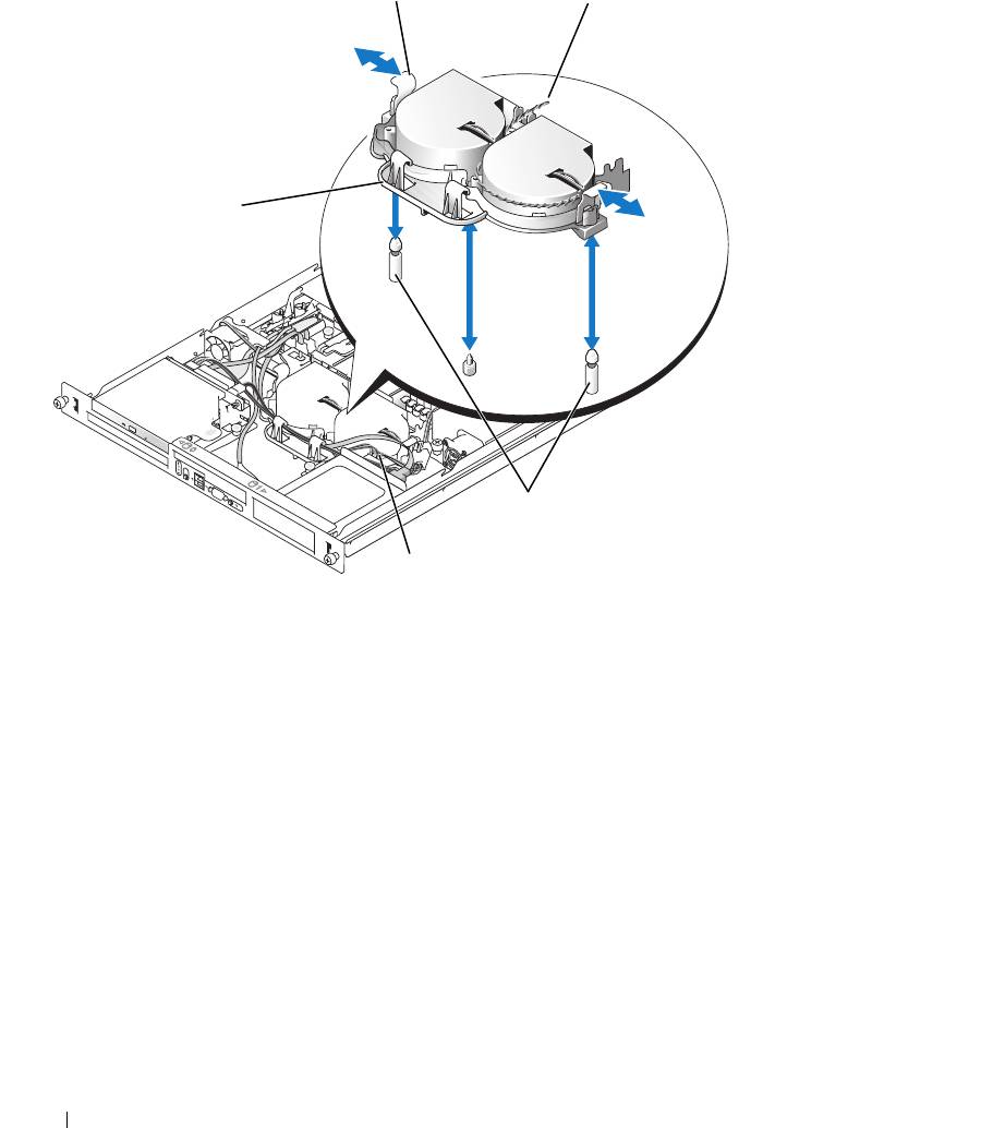
Figure 3-11. Installing and Removing the Fan Assembly
1
2
5
3
4
1 release levers (2) 2 power cable 3 securing posts (2)
4 hard drive 1 data cable 5 cable tray
Installing the Fan Assembly
1
Align the holes in the fan assembly with the two fan assembly securing posts. See Figure 3-11.
2
Lower the fan assembly until the release levers snap onto the securing posts.
3
Route the cables in the fan assembly cable tray. See Figure 3-11.
4
Reconnect the hard drive 1 data cable to the hard drive. See Figure 3-11.
5
Reconnect the fan assembly power cable to the system board.
6
Install the cooling shroud. See "Installing the Cooling Shroud" on page 48.
7
Close the system. See "Closing the System" on page 47.
58 Installing System Components
Optional PCI Fan Assembly
The optional PCI fan module provides cooling for the expansion cards.
NOTICE: Your system requires the PCI fan assembly if your system has a SAS controller that can be connected to
an external storage system. Removing the fan assembly or disabling the fan could result in your system overheating
and shutting down unexpectedly.
Removing the PCI Fan Assembly
CAUTION: Only trained service technicians are authorized to remove the system cover and access any of the
components inside the system. Before performing any procedure, see your Product Information Guide for
complete information about safety precautions, working inside the computer and protecting against electrostatic
discharge.
1
Open the system. See "Opening the System" on page 46.
2
Disconnect the following cables from the system board and SAS controller (if present):
• fan power cable
• intrusion switch cable
• hard drive interface cables
• control panel interface cable
• optical drive interface cable (if present)
3
Pull the interface cables through the panel cutout and fold them out of the way. See Figure 3-12.
4
Using a #2 Phillips screwdriver, remove the two screws securing the PCI fan assembly to the chassis.
See Figure 3-12.
5
Remove the fan assembly from the system.
Installing System Components 59
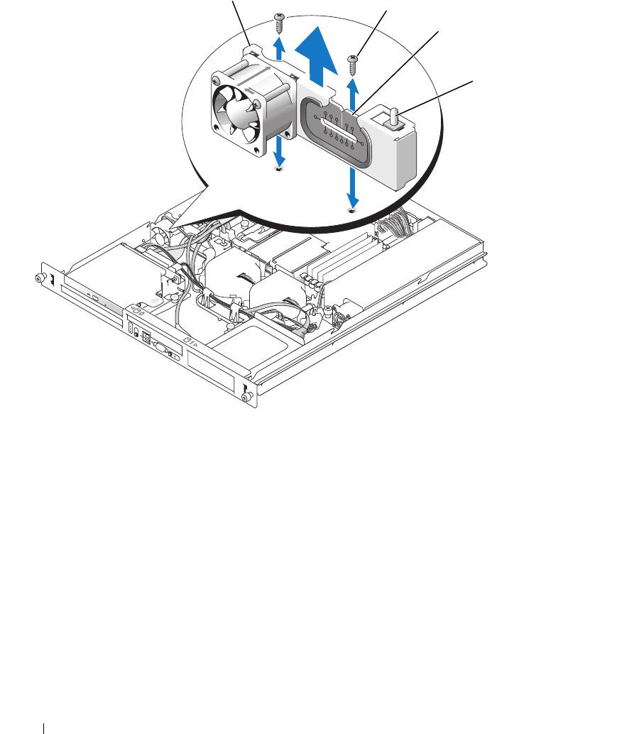
Figure 3-12. Installing and Removing the PCI Fan Assembly
1
2
3
4
1 PCI fan assembly 2 screws (2) 3 panel cutout
4 chassis intrusion switch
Installing the PCI Fan Assembly
1
Align the fan assembly with the screw holes on the chassis and use a #2 Phillips screwdriver to install
the two mounting screws. See Figure 3-12.
2
Connect the fan’s power cable to the PCI FAN connector on the system board. See Figure 6-2 for the
location of the connector.
3
Connect the intrusion switch cable to the INTRUSION_SWITCH connector on the system board.
See Figure 6-2 for the location of the connector.
4
Route all interface connectors through the panel cutout.
5
Connect the hard-drive connectors to the SATA connectors on the system board or to the SAS
controller, if present. See "Installing a Hard Drive" on page 56.
60 Installing System Components
