Beurer FT 65: ELECTROMAGNETIC COMPATIBILITY INFORMATION
ELECTROMAGNETIC COMPATIBILITY INFORMATION: Beurer FT 65
ELECTROMAGNETIC COMPATIBILITY INFORMATION
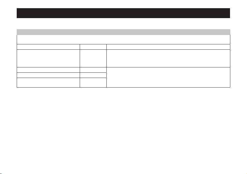
Table 1
Guidance and manufacturer’s declaration-electromagnetic emissions
The FT65 Multi-function Thermometer is intended for use in the electromagnetic environment specied below. The customer or the
user of the FT65 Multi-function Thermometer should assure that it is used in such an environment.
Emissions test Compliance Electromagnetic environment – guidance
RF emissions CISPR 11 Group 1 The FT65 Multi-function Thermometer uses RF energy only for its internal
function.
Therefore, its RF emissions are very low and are not
likely to cause any interference in nearby electronic equipment.
RF emissions CISPR 11 Class B The FT65 Multi-function Thermometer is suitable for use in all establish-
ments other that domestic and those directly connected to the public low-
Harmonic emissions IEC 61000-3-2 Not applicable
voltage power supply network that supplies buildings used for domestic
Voltage uctuations/icker emissions
Not applicable
purposes.
IEC 61000-3-3
109
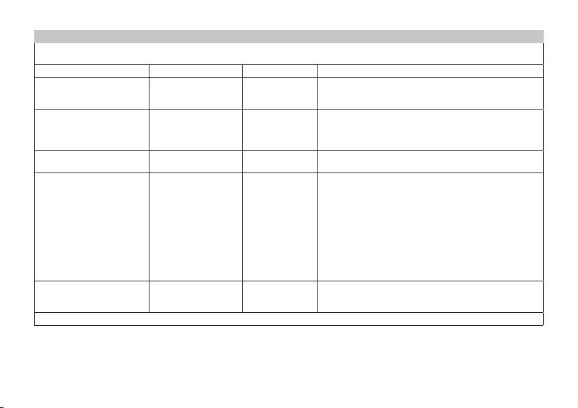
Table 2
Guidance and manufacturer’s declaration – electromagnetic immunity
The FT65 Multi-function Thermometer is intended for use in the electromagnetic environment specied below. The customer or the user
of the FT65 Multi-function Thermometer should assure that it is used in such an environment.
IMMUNITY test IEC 60601 test level Compliance level Electromagnetic environment – guidance
Floor should be wood, concrete or ceramic tile. If oors
Electrostatic discharge (ESD)
± 6 kV contact
± 6 kV contact
are covered with shythetic material, the relative humidity
IEC 61000-4-2
± 8 kV air
± 8 kV air
should be at least 30%.
±2 kV for power
Mains power quality should be that of a typical commercial
Electrical fast transient/burst
supply lines
or hospital environment.
Not applicable
IEC 61000-4-4
±1 kV air for input/out-
put lines
Surge
±1 kV differential mode
Mains power quality should be that of a typical commercial
Not applicable
IEC 61000-4-5
±2 kV common mode
or hospital environment.
<5% U
T
(>95% dip in
Mains power quality should be that of a typical commer-
U
T
for 0.5 cycle
cial or hospital environment. If the use of the FT65 Multi-
function Thermometer requires continued operation dur-
40% U
T
(60% dip in
ing power mains interruptions, it is recommended that the
Voltage dips, short interrup-
U
T
for 5 cycles
FT65 Multi-function Thermometer be powered from an
tions and voltage variations
Not applicable
uninterruptible power supply or a battery.
on power supply input lines
70% U
T
(30% dip in
IEC 61000-4-11
U
T
for 25 cycles
5% U
T
(>95% dip in
U
T
for 5 sec
Power frequency magnetic elds should be at levels char-
Power frequency (50/60 Hz)
3 A/m 3 A/m
acteristic of a typical location in a typical commercial or
magnetic eld IEC 61000-4-8
hospital environment.
NOTE: U
T
is the a.c. mains voltage prior to application of the test level.
110
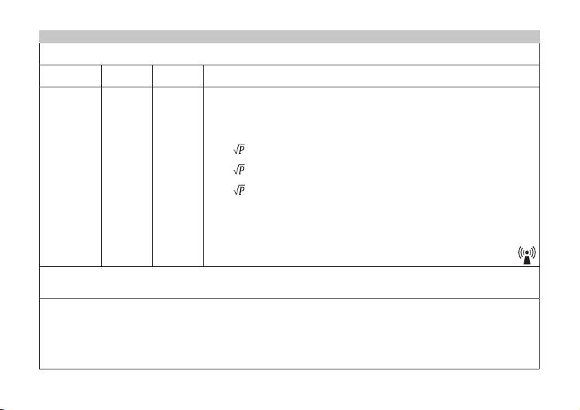
Table 3
Guidance and manufacturer’s declaration – electromagnetic immunity
The FT65 Multi-function Thermometer is intended for use in the electromagnetic environment specied below. The customer or the
user of the FT65 Multi-function Thermometer should assure that it is used in such an environment.
IMMUNITY
IEC 60601
Compli-
Electromagnetic environment – guidance
test
test level
ance level
Portable and mobile RF communications equipment should be used no closer to any part
of the FT65 Multi-function Thermometer, including cables, than the recommended sepa-
ration distance calculated from the equation applicable to the frequency of the transmit-
ter.
Recommended separation distance:
Conducted RF
3V
d = 1.2
rms
3V
rms
IEC 61000-4-6
150 kHz to
80 MHz
d = 1.2
80 MHz to 800 MHz
Radiated RF
3 V / m
3 V / m
d = 2.3
800 MHz to 2.5 GHz
IEC 61000-4-3
80 MHz to
2.5 GHz
Where P is the maximum output power rating of the transmitter in watts (W) according to
the transmitter manufacturer and d is the recommended separation distance in meters
(m).
Field strengths from xed RF transmitters, as determined by an electromagnetic site
survey,
a
should be less than the compliance level in each frequency range.
b
Interference may occur in the vicinity of equipment marked with the following symbol:
NOTE 1 At 80 MHz and 800 MHz, the higher frequency range applies.
NOTE 2 These guidelines may not apply in all situations. Electromagnetic propagation is aected by absorption and reection from
structures, objects and people.
Field strengths from xed transmitters, such as base stations from radio (cellular/cordless) telephones and land mobile radios, ama-
teur radio, AM and FM radio broadcast and TV broadcast can not be predicted theoretic call with accuracy. To assess the elec-
tromagnetic environment due to xed RF transmitters, an electromagnetic site survey should be considered. If the measured eld
strength in the location in which the FT65 Multi-function Thermometer is used exceeds the applicable RF compliance level above, the
FT65 Multi-function Thermometer should be observed to verify normal operation. If abnormal performance is observed, additional
measures may be necessary, such as reorienting or relocating the FT65 Multi-function Thermometer.
Over the frequency range 150kHz to 80MHz, eld strengths should be less than [V1] V/m.
111
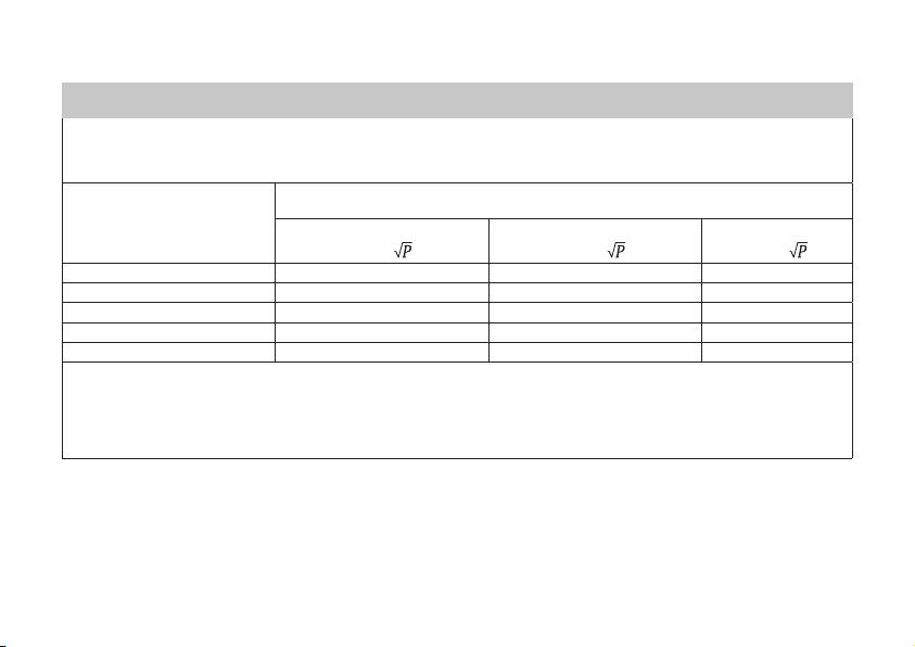
Table 4
Recommended separation distances between portable and mobile RF communications equipment and the EQUIPMENT or
SYSTEM-for EQUIPMENT and SYSTEMS that are not LIFE-SUPPORTING
Recommended separation distances between portable and mobile RF communications equipment and the FT65 Multi-function
Thermometer
The FT65
Multi-function
Thermometer is intended for use in an electromagnetic environment in which radiated RF distances are con-
trolled. The customer or the user of the T FT65
Multi-function
Thermometer can help prevent electromagnetic interference by maintain-
ing a minimum distance between portable and mobile RF communications equipment (transmitters) and the FT65
Multi-function
Ther-
mometer as recommended below according to the maximum output power of the communications equipment.
Separation distance according to frequency of transmitter
(m)
Rated maximum output
150 kHz to 80 MHz
80 MHz to 800 MHz
800 MHz to 2.5 GHz
power of transmitter
(W)
d = 1.2
d = 1.2
d = 2.3
0.01 0.12 0.12 0.23
0.1 0.38 0.38 0.73
1 1.2 1.2 2.3
10 3.8 3.8 7.3
100 12 12 23
For transmitters rated at a maximum output power not listed above, the recommended separation distanced in meters (m) can be
estimated using the equation applicable to the frequency of the transmitter, where P is the maximum output power rating of the trans-
mitter in watts (W) according to the transmitter manufacturer.
NOTE 1 At 80 MHz and 800 MHz, the separation distance for the higher frequency range applies.
NOTE 2 These guidelines may not apply in all situations. Electromagnetic propagation is aected by absorption and reection from
structures, objects and people.
752.373 - 0414 Irrtum und Änderungen vorbehalten
112
