Asus P5QLD PRO: Hardware
Hardware: Asus P5QLD PRO
This chapter lists the hardware setup
procedures that you have to perform
when installing system components. It
includes description of the jumpers and
connectors on the motherboard.
Hardware
2
information

Chapter summary
2
2.1 Before you proceed ..................................................................... 2-1
2.2 Motherboard overview .................................................................
2-2
2.3 Central Processing Unit (CPU) ...................................................
2-6
2.4 System memory .........................................................................
2-12
2.5 Expansion slots ..........................................................................
2-18
2.6 Jumpers ......................................................................................
2-21
2.7 Connectors .................................................................................
2-23
ASUS P5QLD PRO
2.1 Before you proceed
Take note of the following precautions before you install motherboard components
or change any motherboard settings.
• Unplug the power cord from the wall socket before touching any
component.
• Use a grounded wrist strap or touch a safely grounded object or a metal
object, such as the power supply case, before handling components to
avoid damaging them due to static electricity.
• Hold components by the edges to avoid touching the ICs on them.
• Whenever you uninstall any component, place it on a grounded antistatic
pad or in the bag that came with the component.
• Before you install or remove any component, ensure that the ATX power
supply is switched off or the power cord is detached from the power
supply. Failure to do so may cause severe damage to the motherboard,
peripherals, and/or components.
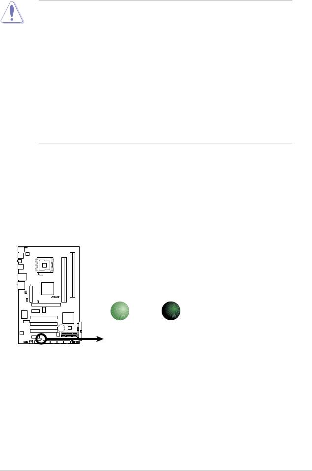
Onboard LED
The motherboard comes with a standby power LED that lights up to indicate that
the system is ON, in sleep mode, or in soft-off mode. This is a reminder that you
should shut down the system and unplug the power cable before removing or
plugging in any motherboard component. The illustration below shows the location
of the onboard LED.
ASUS P5QLD PRO 2-1
SB_PWR
P5QLD PRO
ON
OFF
Standby
Powered
Power
Off
P5QLD PRO Onboard LED
2-2 Chapter 2: Hardware information
P5QLD PRO
2.2 Motherboard overview
Before you install the motherboard, study the conguration of your chassis to
ensure that the motherboard ts into it.
Ensure that you unplug the power cord before installing or removing the
motherboard. Failure to do so can cause you physical injury and damage
motherboard components.
2.2.1 Placement direction
When installing the motherboard, make sure that you place it into the chassis in
the correct orientation. The edge with external ports goes to the rear part of the
chassis as indicated in the image below.
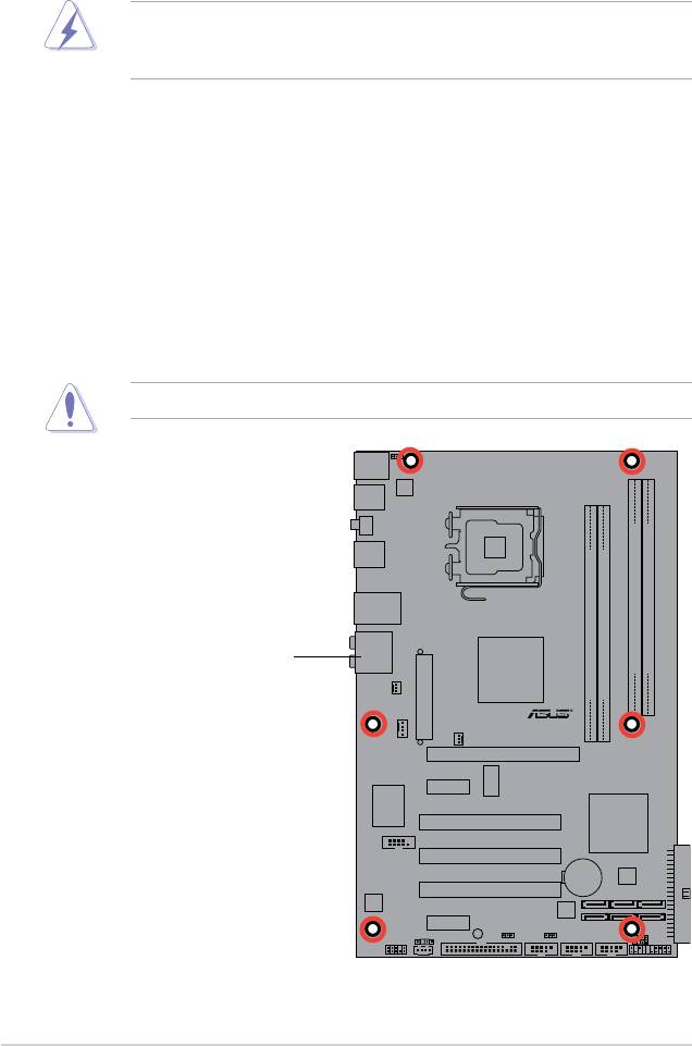
2.2.2 Screw holes
Place six (6) screws into the holes indicated by circles to secure the motherboard
to the chassis.
Do not overtighten the screws! Doing so can damage the motherboard.
Place this side towards
the rear of the chassis
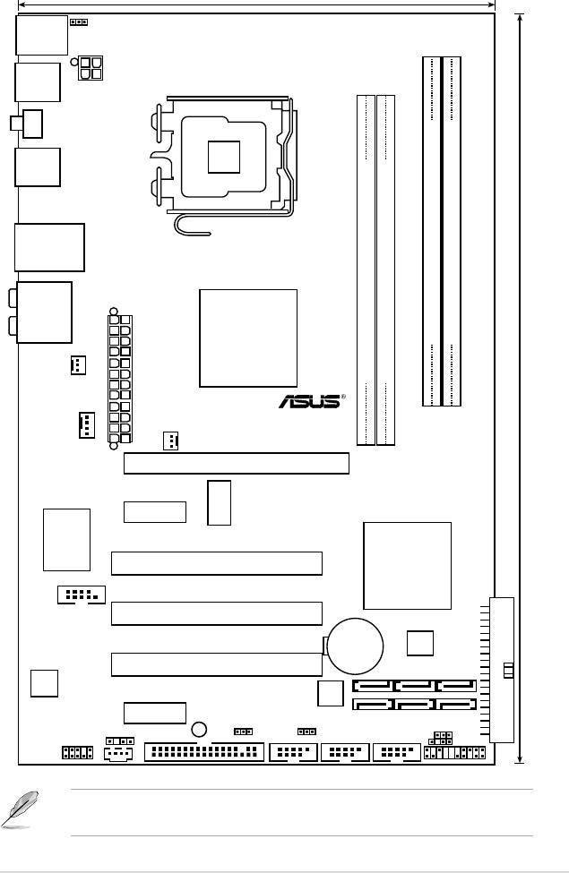
2.2.3 Motherboard layout
Refer to 2.7 Connectors for more information about rear panel connectors and
internal connectors.
ASUS P5QLD PRO 2-3
19.3cm (7.6in)
PS2_USBPW56
PS/2KBMS
T:Mouse
B:Keyboard
USB56
ATX12V
LGA775
SPDIF_O1
USB34
LAN1_USB12
AUDIO
Intel
DDR2 DIMMB1 (64 bit,240-pin module)
DDR2 DIMMB2 (64 bit,240-pin module)
P43
DDR2 DIMMA1 (64 bit,240-pin module)
DDR2 DIMMA2 (64 bit,240-pin module)
CHA_FAN
TXPWR
EA
30.5cm (12in)
CPU_FAN
P5QLD PRO
PWR_FAN
PCIEX16
ICS
PCIEX1_1
9LPRS916JGLF
Super I/O
Intel
PCI1
ICH10
COM1
PCI2
CR2032 3V
4Mb
Lithium Cell
BIOS
CMOS Power
PCI3
ALC
1200
JMB368
PCIEX1_2
SB_PWR
SPDIF_OUT
USBPW1112
CLRTC
CD
USBPW7-10
FLOPPY
AAFP
USB1112 USB78 USB910
CHASSIS
PANEL
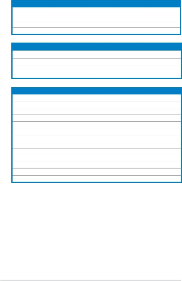
2.2.4 Layout contents
Slots Page
1. DDR2 DIMM slots 2-12
2. PCI slots
2-20
3 PCI Express x1 slot
2-20
4. PCI Express x16 slots
2-20
Jumper Page
1. Clear RTC RAM (3-pin CLRTC) 2-21
2. Keyboard power (3-pin PS2_USBPW56)
2-22
3. USB device wake-up (3-pin USBPW1-4, USBPW7-10,
2-22
USBPW1112)
Rear panel connectors Page
1. PS/2 mouse port (green) 2-23
2. LAN (RJ-45) port
2-23
3. Rear Speaker Out port (black)
2-23
4. Center/Subwoofer port (orange)
2-23
5. Line In port (light blue)
2-23
6. Line Out port (lime)
2-23
7. Microphone port (pink)
2-24
8. Side Speaker Out port (gray)
2-24
9. USB 2.0 ports 1 and 2
2-24
10. USB 2.0 ports 3 and 4
2-24
11. Coaxial S/PDIF Out port
2-24
12. USB 2.0 ports 5 and 6
2-24
13. PS/2 keyboard port (purple)
2-24
2-4 Chapter 2: Hardware information
Internal connectors Page
1. Floppy disk drive connector (34-1 pin FLOPPY) 2-25
2. Digital audio connector (4-1 pin SPDIF_OUT) 2-25
3. IDE connector (40-1 pin PRI_EIDE) 2-26
4. Serial ATA connectors (7-pin SATA1-6) 2-27
5. USB connectors (10-1 pin USB78, USB910, USB1112)
2-28
6. Optical drive audio connector (4-pin CD) 2-28
7. CPU, chassis, and power fan connectors (4-pin CPU_FAN,
2-29
3-pin CHA_FAN, 3-pin PWR_FAN)
8. Serial port connector (10-1 pin COM1)
2-29
9. Chassis intrusion connector (4-1 pin CHASSIS) 2-30
10. Front panel audio connector (10-1 pin AAFP)
2-30
11. ATX power connectors (24-pin EATXPWR, 4-pin EATX12V)
2-31
12. System panel connector (20-8 pin PANEL)
2-32
• System power LED (2-pin PLED)
• Hard disk drive activity LED (2-pin IDE_LED)
• System warning speaker (4-pin SPEAKER)
• ATX power button/soft-off button (2-pin PWRSW)
• Reset button (2-pin RESET)
ASUS Q-connector (system panel) 2-33
ASUS P5QLD PRO 2-5
2.3 Central Processing Unit (CPU)
The motherboard comes with a surface mount LGA775 socket designed for the
®
®
Intel
Core™2 Extreme / Core™2 Quad / Core™2 Duo / Pentium
Dual-Core /
®
®
Celeron
Dual-Core / Celeron
processors.
• Ensure that all power cables are unplugged before installing the CPU.
• Connect the chassis fan cable to the CHA_FAN connector to ensure
system stability.
•
Upon purchase of the motherboard, make sure that the PnP cap is on
the socket and the socket contacts are not bent. Contact your retailer
immediately if the PnP cap is missing, or if you see any damage to the PnP
cap/socket contacts/motherboard components. ASUS will shoulder the cost
of repair only if the damage is shipment/transit-related.
•
Keep the cap after installing the motherboard. ASUS will process Return
Merchandise Authorization (RMA) requests only if the motherboard comes
with the cap on the LGA775 socket.
• The product warranty does not cover damage to the socket contacts
resulting from incorrect CPU installation/removal, or misplacement/loss/
incorrect removal of the PnP cap.
2-6 Chapter 2: Hardware information
2.3.1 Installing the CPU
To install a CPU:
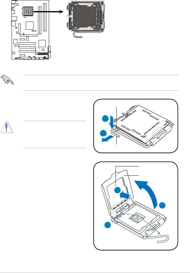
1. Locate the CPU socket on the motherboard.
Before installing the CPU, ensure that the socket box is facing towards you and
the load lever is on your left.
ASUS P5QLD PRO 2-7
P5QLD PRO
P5QLD PRO
CPU Socket 775
2. Press the load lever with your thumb
Retention tab
(A), then move it to the left (B) until it
is released from the retention tab.
A
To prevent damage to the
socket pins, do not remove
B
the PnP cap unless you are
installing a CPU.
Load lever
3. Lift the load lever in the direction of
PnP cap
the arrow to a 135º angle.
Load plate
4B
4. Lift the load plate with your thumb
and forenger to a 100º angle (4A),
then push the PnP cap from the
4A
load plate window to remove (4B).
3
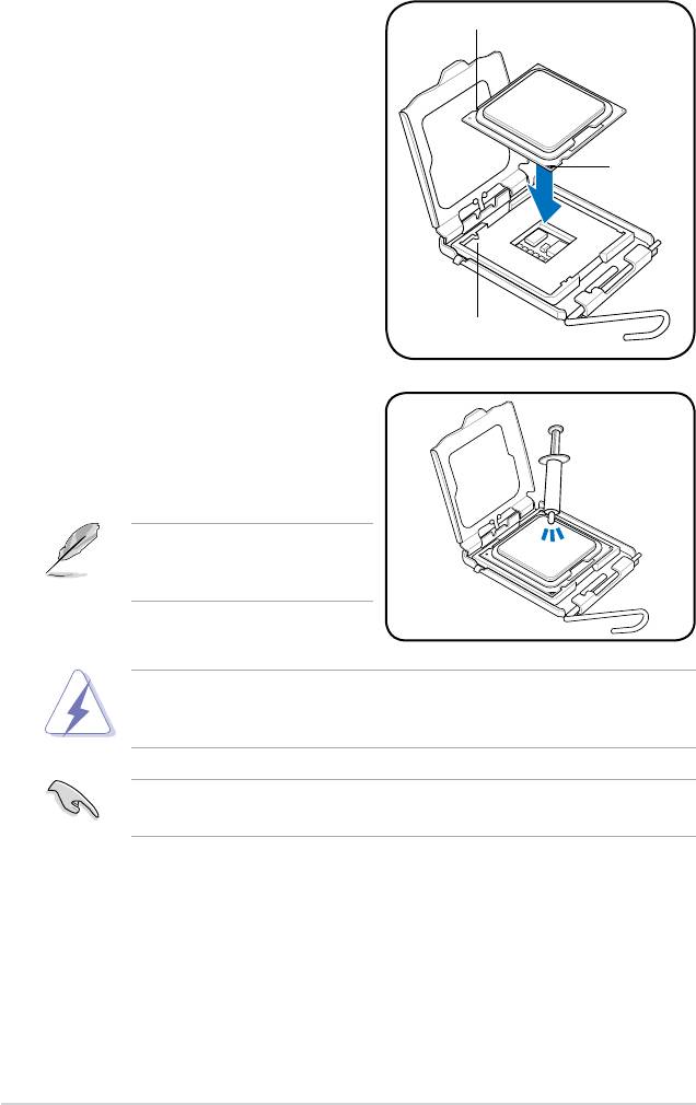
5. Position the CPU over the socket,
CPU notch
ensuring that the gold triangle is on
the bottom-left corner of the socket
then t the socket alignment key
into the CPU notch.
Gold
triangle
mark
Alignment key
6. Apply several drops of Thermal
Interface Material to the exposed
area of the CPU that the heatsink will
be in contact with, ensuring that it is
spread in an even thin layer.
Some heatsinks come with pre-
applied thermal paste. If so, skip
this step.
DO NOT eat the Thermal Interface Material. If it gets into your eyes or touches
your skin, ensure that you wash it off immediately, and seek professional
medical help.
To prevent contaminating the paste, DO NOT spread the paste with your nger
directly.
2-8 Chapter 2: Hardware information
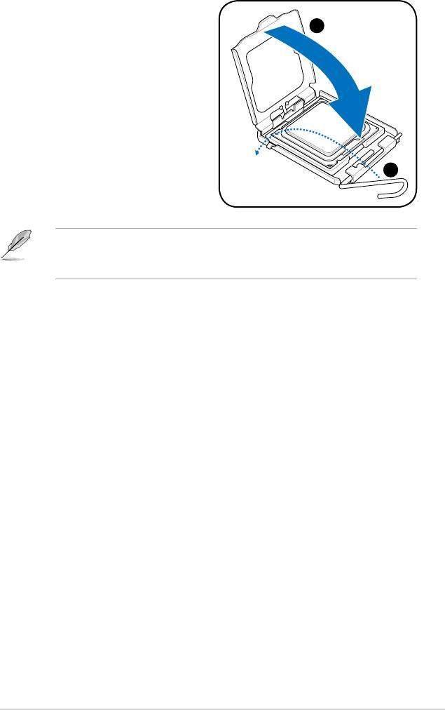
7. Close the load plate (A), then push
the load lever (B) until it snaps into
A
the retention tab.
B
®
®
The motherboard supports Intel
LGA775 processors with the Intel
Enhanced
®
Intel SpeedStep
Technology (EIST) and Hyper-Threading Technology. Refer to
the Appendix for more information on these CPU features.
ASUS P5QLD PRO 2-9
2.3.2 Installing the CPU heatsink and fan
®
The Intel
LGA775 processor requires a specially designed heatsink and fan
assembly to ensure optimum thermal condition and performance.
®
•
When you buy a boxed Intel
processor, the package includes the CPU fan
and heatsink assembly. If you buy a CPU separately, ensure that you use
®
only Intel
-certied multi-directional heatsink and fan.
®
• Your Intel
LGA775 heatsink and fan assembly comes in a push-pin design
and requires no tool to install.
• If you purchased a separate CPU heatsink and fan assembly, make sure
that you have properly applied Thermal Interface Material to the CPU
heatsink or CPU before you install the heatsink and fan assembly.
Ensure that you have installed the motherboard to the chassis before you install
the CPU fan and heatsink assembly.
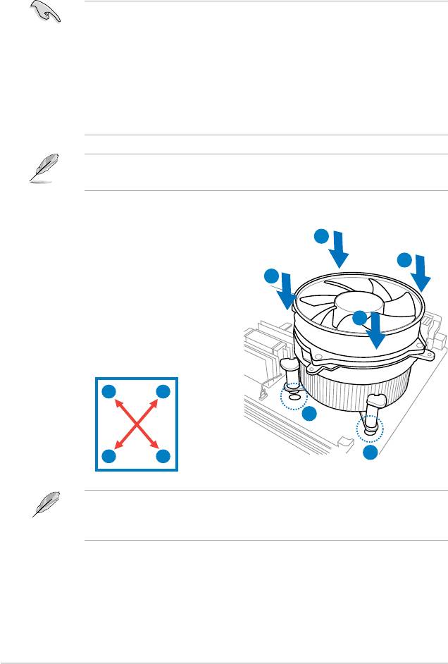
To install the CPU heatsink and fan:
A
1. Place the heatsink on top of the
B
installed CPU, making sure that the
B
four fasteners match the holes on
the motherboard.
A
2. Push down two fasteners at a time in
a diagonal sequence to secure the
heatsink and fan assembly in place.
A
B
1
1
B
A
The type of CPU heatsink and fan assembly may differ, but the installation steps
and fucntions should remain the same. The illustration above is for reference
only.
2-10 Chapter 2: Hardware information
3. Connect the CPU fan cable to the connector on the motherboard labeled
CPU_FAN.
Do not forget to connect the CPU fan connector! Hardware monitoring errors
can occur if you fail to plug this connector.
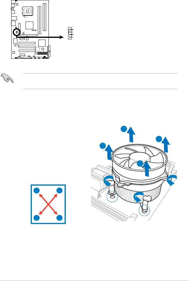
2.3.3 Uninstalling the CPU heatsink and fan
To uninstall the CPU heatsink and fan
1. Disconnect the CPU fan cable from
A
the connector on the motherboard.
B
2. Rotate each fastener
B
counterclockwise.
3. Pull up two fasteners at a time in a
diagonal sequence to disengage the
A
heatsink and fan assembly from the
motherboard.
A
B
B
A
4. Carefully remove the heatsink and fan assembly from the motherboard.
ASUS P5QLD PRO 2-11
CPU_FAN
GND
P5QLD PRO
CPU FAN PWR
CPU FAN IN
CPU FAN PWM
P5QLD PRO
CPU Fan Connector
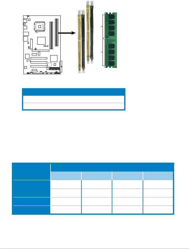
2.4 System memory
2.4.1 Overview
The motherboard comes with four Double Data Rate 2 (DDR2) Dual Inline Memory
Modules (DIMM) sockets.
The gure illustrates the location of the DDR2 DIMM sockets:
Channel Sockets
Channel A DIMM_A1 and DIMM_A2
Channel B DIMM_B1 and DIMM_B2
2-12 Chapter 2: Hardware information
DIMM_B1
DIMM_B2
DIMM_A1
DIMM_A2
112 Pins
P5QLD PRO
128 Pins
P5QLD PRO
240-pin DDR2 DIMM Sockets
2.4.2 Memory congurations
You may install 512MB, 1GB, 2GB, and 4GB unbuffered non-ECC DDR2 DIMMs
into the DIMM sockets.
Recommended Memory Congurations
Sockets
Mode
DIMM_A1 DIMM_A2 DIMM_B1 DIMM_B2
- - Populated -
Single-Channel
Populated - - -
Dual-channel (1) Populated - Populated -
Dual-channel (2) Populated Populated Populated Populated

• You may install varying memory sizes in Channel A and Channel B. The
system maps the total size of the lower-sized channel for the dual-channel
conguration. Any excess memory from the higher-sized channel is then
mapped for single-channel operation.
• Always install DIMMs with the same CAS latency. For optimum compatibility,
it is recommended that you obtain memory modules from the same vendor.
®
• Due to the memory address limitation on 32-bit Windows
OS, when you
install 4GB or more memory on the motherboard, the actual usable memory
for the OS can be about 3GB or less. For effective use of memory, we
recommend that you do any of the following:
®
- Use a maximum of 3GB system memory if you are using a 32-bit Windows
OS.
®
- Install a 64-bit Windows
OS when you want to install 4GB or more memory
on the motherboard.
• This motherboard does not support DIMMs made up of 256 megabits (Mb)
chips or less.
• The default memory operation frequency is dependent on its SPD. Under
the default state, some memory modules for overclocking may operate at a
lower frequency than the vendor-marked value. To operate at the vendor-
marked or at a higher frequency, see section 4.4 Ai Tweaker menu for
manual memory frequency adjustment.
• The memory modules may require a better cooling system to work stably
under full loading (4 DIMMs) or overclocking setting.
®
• Some old-version DDR2-800 DIMMs may not match Intel
’s
On-Die-Termination (ODT) requirement and will automatically downgrade
to run at DDR2-667. If this happens, contact your memory vendor to check
the ODT value.
• Due to chipset limitation, DDR2-800 with CL=4 will be downgraded to run
at DDR2-667 by default setting. If you want to operate with lower latency,
adjust the memory timing manually.
ASUS P5QLD PRO 2-13
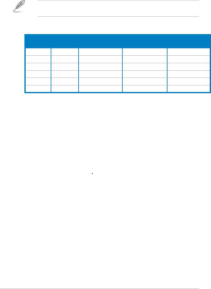
P5QLD PRO Motherboard Qualied Vendors Lists (QVL)
DDR2-1066MHz capability
SS/
DIMM support
Size Vendor Part No. CL Chip Brand
Chip No.
DS
A* B* C*
512MB Kingston KHX8500D2/512 N/A Kingston SS Heat-Sink Package . .
512MB Kingston KVR1066D2N7/512 N/A Elpida SS E5108AJBG-1J-E . . .
1G Kingston KHX8500D2K2/2GN N/A Kingston DS Heat-Sink Package .
1G Kingston KVR1066D2N7/1G N/A Elpida DS E5108AJBG-1J-E . . .
1G Kingston KHX8500D2/1G N/A Kingston DS Heat-Sink Package . . .
1G Qimonda HYS64T128020EU-19F-C 6 Qimonda DS HYB18T512800CF19FFSS24313 . . .
1G Kingmax KLED48F-A8K15 N/A Kingmax DS KKA8FFIXF-JFS-18A . .
1G Transcend TX1066QLJ-2GK1GB 5 Transced DS Heat-Sink Package . .
1G GEIL GB22GB8500C5DC 5 GEIL SS GL2L128M88BA25AB . .
1G GEIL GB24GB8500C5QC 5 GEIL SS GL2L128M88BA25AB . . .
1G GEIL GE22GB1066C5DC 5 GEIL DS Heat-Sink Package . . .
1G GEIL GE24GB1066C5QC 5 GEIL DS Heat-Sink Package . .
2G GEIL GB24GB8500C5DC 5 GEIL DS GL2L128M88BA25AB . . .
512MB AENEON AXT660UD00-19DC97X 5 AENEON SS Heat-Sink Package .
1G AENEON AXT760UD00-19DC97X 5 AENEON DS Heat-Sink Package . . .
If you install a DDR2-1066 memory module whose SPD is DDR2-800, ensure
that you set the DRAM Frequency item in BIOS to [DDR2-1066MHz]. See
section 4.4 Ai Tweaker menu for details.
DDR2-800MHz capability
SS/
DIMM support
Size Vendor Part No. CL Chip Brand
Chip No.
DS
A* B* C*
1G Kingston KHX6400D2LL/1G N/A Kingston DS Heat-Sink Package . . .
512MB Kingston KHX6400D2LLK2/1GN N/A Kingston SS Heat-Sink Package . . .
512MB Kingston KVR800D2N5/512 N/A Promos SS V59C1512804QCF25SY032406PECPA . . .
512MB Kingston KVR800D2N6/512 N/A Elpida SS E5108AJBG-8E-E . . .
1G Kingston KVR800D2N5/1G N/A Elpida DS E5108AJBG-8E-E . . .
1G Kingston KVR800D2N6/1G N/A Elpida DS E5108AJBG-8E-E . . .
2G Kingston KVR800D2N5/2G N/A Elpida DS E1108ACBG-8E-E . . .
4G Kingston N/A N/A Elpida DS E2108ABSE-8G-E . . .
512MB Samsung M378T6553GZS-CF7 6 Samsung SS K4T51083QG-HCF7 . . .
1G Samsung M378T2863QZS-CF7 6 Samsung SS K4T1G084QQ-HCF7 . . .
1G Samsung M378T2953GZ3-CF7 6 Samsung DS K4T51083QG-HCF7 . . .
2G Samsung M37875663QZ3-CF7 6 Samsung DS K4T1G084QQ-HCF7 . . .
512MB Qimonda HYS64T64000EU-2.5-B2 6 Qimonda SS HYB18T512800B2F25FSS28380 . .
1G Qimonda HYS64T128020EU-2.5-B2 6 Qimonda DS HYB18T512800B2F25FSS28380 . .
1G Corsair XMS2-6400 4 Corsair DS Heat-Sink Package . . .
1G Corsair XMS2-6400 5 Corsair DS Heat-Sink Package . . .
512MB HY HYMP564U64CP8-S5 AB 5 Hynix SS HY5PS12821CFP-S5 . . .
1G HY HYMP512U64CP8-S5 AB 5 Hynix DS HY5PS12821CFPS5 . . .
512MB Kingmax KLDC28F-A8KI5 N/A Kingmax SS KKA8FF1XF-JFS-25A . . .
1G Kingmax KLDD48F-A8K15 N/A Kingmax DS KKA8FFIXF-HFS-25A . . .
512MB Apacer 78.91G91.9K5 5 Apacer SS AM4B5708JQJS8E0751C . . .
1G Apacer 78.01GA0.9K5 5 Apacer SS AM4B5808CQJS8E0749D . . .
2G Apacer 78.A1GA0.9K4 5 Apacer DS AM4B5808CQJS8E0747D . . .
(continued on the next page)
2-14 Chapter 2: Hardware information

DDR2-800MHz capability
SS/
DIMM support
Size Vendor Part No. CL Chip Brand
Chip No.
DS
A* B* C*
512MB Transcend TS128MLQ64V8J512MB N/A Micron SS 7HD22 D9GMH . . .
512MB Transcend TS64MLQ64V8J512MB N/A Transcend SS Heat-Sink Package . . .
512MB ADATA M2OAD6G3H3160Q1E58 N/A ADATA SS AD29608A8A-25EG80812 . . .
512MB VDATA M2GVD6G3H3160Q1E52 N/A VDATA SS VD29608A8A-25EG20813 . . .
1G ADATA M2OAD6G314170Q1E58 N/A ADATA DS AD29608A8A-25EG80810 . . .
1G VDATA M2GVD6G314170Q1E58 N/A VDATA DS VD29608A8A-25EG80813 . . .
1G PSC AL7E8F73C-8E1 5 PSC SS A3R1GE3CFF734MAA0E . . .
2G PSC AL8E8F73C-8E1 5 PSC DS A3R1GE3CFF734MAA0E . . .
1G GEIL GB22GB6400C4DC 4 GEIL DS GL2L64M088BA30EB . . .
1G GEIL GB24GB6400C4QC 4 GEIL DS GL2L64M088BA30EB . . .
1G GEIL GB22GB6400C5DC 5 GEIL DS GL2L64M088BA30EB . . .
1G GEIL GB24GB6400C5QC 5 GEIL DS GL2L64M088BA30EB . . .
1G GEIL GX22GB6400DC 5 GEIL DS Heat-Sink Package . . .
1G GEIL GE22GB800C4DC 4 GEIL DS Heat-Sink Package . . .
1G GEIL GE24GB800C4QC 4 GEIL DS Heat-Sink Package . . .
1G GEIL GX22GB6400UDC 4 GEIL DS Heat-Sink Package . . .
1G GEIL GE22GB800C5DC 5 GEIL DS Heat-Sink Package . . .
1G GEIL GE24GB800C5QC 5 GEIL DS Heat-Sink Package . . .
2G GEIL GB24GB6400C4DC 4 GEIL DS GL2L128M88BA25AB . .
2G GEIL GB24GB6400C5DC 5 GEIL DS GL2L128M88BA25AB . . .
2G GEIL GB28GB6400C5QC 5 GEIL DS GL2L128M88BA25AB . . .
2G GEIL GB28GB6400C4QC 4 GEIL DS GL2L128M88BA25AB . .
2G GEIL GX22GB6400LX 5 GEIL DS Heat-Sink Package . . .
2G GEIL GX24GB6400DC 5 GEIL DS Heat-Sink Package . . .
2G GEIL GE28GB800C5QC 5 GEIL DS Heat-Sink Package . . .
2G GEIL GE28GB800C4QC 4 GEIL DS Heat-Sink Package . . .
2G GEIL GX22GB6400CUSC 4 GEIL DS Heat-Sink Package . . .
2G GEIL GE24GB800C4DC 4 GEIL DS Heat-Sink Package . . .
2G GEIL GE24GB800C5DC 5 GEIL DS Heat-Sink Package . . .
1G Super Talent T800UB1GC4 4 Super Talent DS Heat-Sink Package . . .
1G G.SKILL F2-6400CL5D-2GBNQ 5 G.SKILL DS Heat-Sink Package . . .
1G G.SKILL F2-6400CL4D-2GBPK 4 G.SKILL DS Heat-Sink Package . . .
1G G.SKILL F2-6400CL4D-2GBHK 4 G.SKILL DS Heat-Sink Package . . .
2G G.SKILL F2-6400CL5D-4GBPQ 5 G.SKILL DS Heat-Sink Package . . .
2G G.SKILL F2-6400CL4D-4GBPK 4 G.SKILL DS Heat-Sink Package . . .
4G G.SKILL F2-6400CL5Q-16GNQ 5 G.SKILL DS Heat-Sink Package .
1G OCZ OCZ2RPR8002GK 4 OCZ DS Heat-Sink Package . . .
1G OCZ OCZ2G800R22GK 5 OCZ DS Heat-Sink Package . . .
1G OCZ OCZ2P800R22GK 4 OCZ DS Heat-Sink Package . . .
1G OCZ OCZ2VU8004GK 6 OCZ DS Heat-Sink Package . .
2G OCZ OCZ2P8004GK 5 OCZ DS Heat-Sink Package . .
1G Elixir M2Y1G64TU8HB0B-25C 5 Elixir DS N2TU51280BE-25C802006Z1DV . . .
ASUS P5QLD PRO 2-15
DDR2-667MHz capability
SS/
DIMM support
Size Vendor Part No. CL Chip Brand
Chip No.
DS
A* B* C*
512MB Kingston KVR667D2N5/512 N/A Hynix SS HY5PS12821EFP-Y5 . . .
1G Kingston KVR667D2N5/1G N/A Hynix DS HY5PS12821EFP-Y5 . . .
2G Kingston KVR667D2N5/2G N/A Micron DS 7RE22 D9HNL . . .
512MB Qimonda HYS64T64000EU-3S-B2 5 Qimonda SS HYB18T512B00B2F3SFSS28171 . . .
1G Qimonda HYS64T128020EU-3S-B2 5 Qimonda DS HYB18T512B00B2F3SFSS28171 . . .
512MB Corsair VS512MB667D2 N/A Corsair SS 64M8CFEGPS0900647 . . .
1G Corsair VS1GB667D2 N/A Corsair DS MID095D62864M8CEC . . .
1G Corsair XMS2-5400 4 Corsair DS Heat-Sink Package . . .
1G HY HYMP512U64CP8-Y5 AB 5 Hynix DS HY5PS12521CFP-Y5 . . .
512MB Kingmax KLCC28F-A8KB5 N/A Kingmax SS KKEA88B4LAUG-29DX . . .
1G Kingmax KLCD48F-A8KB5 N/A Kingmax DS KKEA88B4LAUG-29DX . . .
512MB Apacer AU512E667C5KBGC 5 Apacer SS AM4B5708MIJS7E0627B . . .
512MB Apacer AU512E667C5KBGC 5 Apacer SS AM4B5708GQJS7E06332F . . .
512MB Apacer 78.91G92.9K5 5 Apacer SS AM4B5708JQJS7E0751C . . .
1G Apacer 78.01G9O.9K5 5 Apacer SS AM4B5808CQJS7E0751C . . .
1G Apacer AU01GE667C5KBGC N/A Apacer DS AM4B5708GQJS7E0636B . . .
1G Apacer AU01GE667C5KBGC 5 Apacer DS AM4B5708MIJS7E0627B . . .
2G Apacer 78.A1G9O.9K4 5 Apacer DS AM4B5808CQJS7E0749B . . .
1G Transcend 506010-4894 5 Elpida DS E5108AJBG-6E-E . . .
512MB ADATA M2OAD5G3H3160Q1C52 N/A ADATA SS AD29608A8A-3EG20813 . . .
2G ADATA M2OAD5H3J4170I1C53 N/A ADATA DS AD20908A8A-3EG 30724 . . .
512MB PSC AL6E8E63J-6E1 5 PSC SS A3R12E3JFF717B9A00 . . .
1G PSC AL7E8E63J-6E1 5 PSC DS A3R12E3JFF717B9A01 . . .
1G PSC AL7E8F73C-6E1 5 PSC SS A3R1GE3CFF734MAA0J . . .
2G PSC AL8E8F73C-6E1 5 PSC DS A3R1GE3CFF733MAA00 . . .
512MB Nanya NT512T64U88A1BY-3C N/A Nanya SS NT5TU64M8AE-3C . . .
1G Nanya NT1GT64U8HB0BY-3C 5 Nanya DS NT5TU64M8BE-3C72155700CP . . .
1G GEIL GX21GB5300SX 3 GEIL DS Heat-Sink Package . . .
2G GEIL GX22GB5300LX 5 GEIL DS Heat-Sink Package . .
2G GEIL GX24GB5300LDC 5 GEIL DS Heat-Sink Package . . .
1G Super Talent T667UB1GV 5 Super Talent DS PG 64M8-800 0750 . . .
512MB Twinmos 8D-A3JK5MPETP 5 PSC SS A3R12E3GEF633ACAOY . . .
1G ELIXIR M2Y1G64TU8HA2B-3C 5 ELIXIR DS M2TU51280AE-3C717095R28F . . .
1G ELIXIR M2Y1G64TU8HBOB-3C 5 ELIXIR DS N2TU51280BE-3C639009W1CF . . .
1G Leadmax LRMP512U64A8-Y5 N/A Hynix DS HY5PS12821CFP-Y5 C 702AA . . .
SS - Single-sided / DS - Double - sided
DIMM support:
• A*: Supports one module inserted into any slot as Single-channel memory
conguration.
• B*: Supports one pair of modules inserted into either the yellow slots or the
black slots as one pair of Dual-channel memory conguration.
• C*: Supports four modules inserted into both the yellow slots and the black
slots as two pairs of Dual-channel memory conguration.
Visit the ASUS website for the latest DDR2-1066/800/667MHz QVL.
2-16 Chapter 2: Hardware information
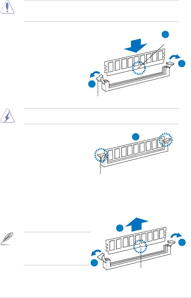
2.4.3 Installing a DIMM
Unplug the power supply before adding or removing DIMMs or other
system components. Failure to do so can cause severe damage to both the
motherboard and the components.
2
1. Unlock a DDR2 DIMM socket
DDR2 DIMM notch
by pressing the retaining clips
outward.
2. Align a DIMM on the socket
1
such that the notch on the DIMM
matches the break on the socket.
1
Unlocked retaining clip
A DDR2 DIMM is keyed with a notch so that it ts in only one direction. DO NOT
force a DIMM into a socket to avoid damaging the DIMM.
3. Firmly insert the DIMM into the
3
socket until the retaining clips snap
back in place and the DIMM is
properly seated.
Locked Retaining Clip
2.4.4 Removing a DIMM
To remove a DIMM:
1. Simultaneously press the retaining
clips outward to unlock the DIMM.
2
Support the DIMM lightly with
1
your ngers when pressing the
retaining clips. The DIMM might
get damaged when it ips out
with extra force.
1
DDR2 DIMM notch
2. Remove the DIMM from the socket.
ASUS P5QLD PRO 2-17
2.5 Expansion slots
In the future, you may need to install expansion cards. The following sub-sections
describe the slots and the expansion cards that they support.
Ensure to unplug the power cord before adding or removing expansion cards.
Failure to do so may cause you physical injury and damage motherboard
components.
2.5.1 Installing an expansion card
To install an expansion card:
1. Before installing the expansion card, read the documentation that came with
it and make the necessary hardware settings for the card.
2. Remove the system unit cover (if your motherboard is already installed in a
chassis).
3. Remove the bracket opposite the slot that you intend to use. Keep the screw
for later use.
4. Align the card connector with the slot and press rmly until the card is
completely seated on the slot.
5. Secure the card to the chassis with the screw you removed earlier.
6. Replace the system cover.
2.5.2 Conguring an expansion card
After installing the expansion card, congure it by adjusting the software settings.
1. Turn on the system and change the necessary BIOS settings, if any. See
Chapter 4 for information on BIOS setup.
2. Assign an IRQ to the card. Refer to the tables on the next page.
3. Install the software drivers for the expansion card.
When using PCI cards on shared slots, ensure that the drivers support “Share
IRQ” or that the cards do not need IRQ assignments. Otherwise, conicts will
arise between the two PCI groups, making the system unstable and the card
inoperable. Refer to the table on the next page for details.
2-18 Chapter 2: Hardware information
2.5.3 Interrupt assignments
Standard interrupt assignments
IRQ Standard function
0 System timer
1 Standard 101/102-Key or Microsoft Natural Keyboard
2 Free
3 Free
4 Communications port (COM1)
5 Free
6 Standard oppy
7 Free
8 System CMOS/Real Time Clock
9 Microsoft ACPI-compliant system
10 Free
11 Free
12 Microsoft PS/2 mouse port
13 Numeric data processor
14 Free
15 Intel® ICH10 Family SM Bus controller-3A30
IRQ assignments for this motherboard
A B C D E F G H
PCIE X1 slot shared shared shared shared - - - -
PCIE X1 slot shared shared shared shared - - - -
PCIE X16 slot shared shared shared shared - - - -
Onboard USB1.1 controller 1 - - - - - - - shared
Onboard USB1.1 controller 2 - - - shared - - - -
Onboard USB1.1 controller 3 - - shared - - - - -
Onboard USB1.1 controller 4 shared - - - - - - -
Onboard USB1.1 controller 5 shared - - - - - - -
Onboard USB1.1 controller 6 - - - - - shared - -
Onboard USB1.1 controller 7 - - shared - - - - -
Onboard USB2.0 controller 1 - - - - - - - shared
Onboard USB2.0 controller 2 - - shared - - - - -
Onboard IDE PORT shared - - - - - - -
Onboard HD Audio - - - - - - shared -
Onboard LAN - shared - - - - - -
Onchip SATA1 - - shared shared - - - -
Onchip SATA2 - - shared - - - - -
PCI Card1 shared shared shared shared - - - -
PCI Card2 shared shared shared shared - - - -
PCI Card3 shared shared shared shared - - - -
ASUS P5QLD PRO 2-19
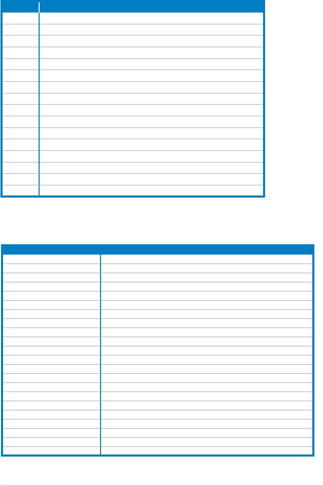
2.5.4 PCI slots
The PCI slots support cards such as
a LAN card, SCSI card, USB card,
and other cards that comply with PCI
specications. The photo shows a LAN
card installed on a PCI slot.
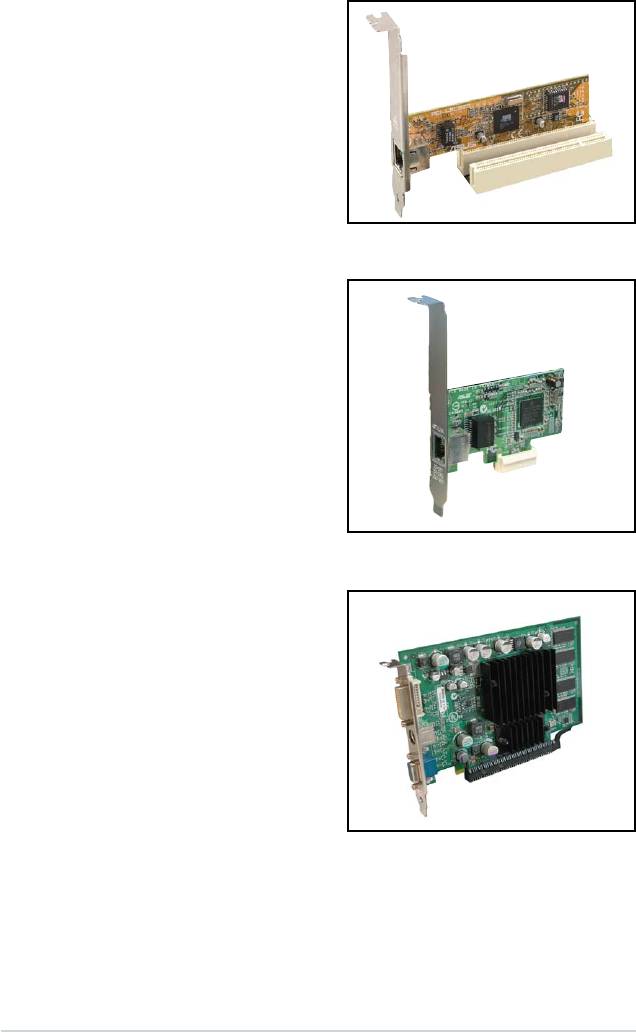
2.5.5 PCI Express x1 slots
This motherboard supports PCI Express
x1 network cards, SCSI cards and other
cards that comply with the PCI Express
specications. The following photo
shows a network card installed on the
PCI Express x1 slot.
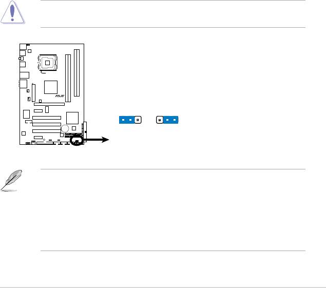
2.5.6 PCI Express x16 slot
This motherboard supports one PCI
Express x16 graphics card that complies
with the PCI Express specications. The
photo shows a graphics card installed
on the PCI Express x16 slot.
2-20 Chapter 2: Hardware information
2.6 Jumpers
1. Clear RTC RAM (3-pin CLRTC)
This jumper allows you to clear the Real Time Clock (RTC) RAM in
CMOS. You can clear the CMOS memory of date, time, and system setup
parameters by erasing the CMOS RTC RAM data. The onboard button
cell battery powers the RAM data in CMOS, which include system setup
information such as system passwords.
To erase the RTC RAM:
1. Turn OFF the computer and unplug the power cord.
2. Remove the onboard battery.
3. Move the jumper cap from pins 1-2 (default) to pins 2-3. Keep the cap on
pins 2-3 for about 5~10 seconds, then move the cap back to pins 1-2.
4. Reinstall the battery.
5. Plug the power cord and turn ON the computer.
6. Hold down the <
Del> key during the boot process and enter BIOS setup
to re-enter data.
Except when clearing the RTC RAM, never remove the cap on CLRTC jumper
default position. Removing the cap will cause system boot failure!
• You do not need to clear the RTC when the system hangs due to
overclocking. For system failure due to overclocking, use the C.P.R. (CPU
Parameter Recall) feature. Shut down and reboot the system so the BIOS
can automatically reset parameter settings to default values.
• Due to the chipset limitation, AC power off is required prior using C.P.R.
function. You must turn off and on the power supply or unplug and plug the
power cord before reboot the system.
ASUS P5QLD PRO 2-21
P5QLD PRO
CLRTC
1 2 2 3
Normal
Clear RTC
(Default)
P5QLD PRO
Clear RTC RAM
2-22 Chapter 2: Hardware information
PS2_USBPW56
1
2
2
3
+5V
+5VSB
(D
e
fa
u
lt
)
P5QLD PRO
P5QLD PRO
Keyboard Power Setting
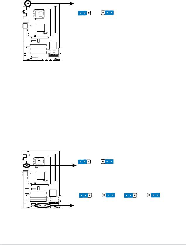
2. Keyboard power (3-pin PS2_USBPW56)
This jumper allows you to enable or disable the keyboard and USB port 5-6
wake-up feature. When you set this jumper to pins 2-3 (+5VSB), you can
wake up the computer by pressing a key on the keyboard (the default is
the Space Bar) or using a USB device. This feature requires an ATX power
supply that can supply at least 1A on the +5VSB lead, and a corresponding
setting in the BIOS. The jumper is for the rear USB ports.
USBPW1-4
1
2
2
3
+5V
+5VSB
(D
e
fa
u
lt
)
P5QLD PRO
USBPW1112
USBPW7-10
1
2
2
3
1
2
2
3
+5
V
+5VSB
+5
V
+5VSB
(D
e
fault)
(D
e
fault)
P5QLD PRO
USB Device Wake Up
3. USB device wake-up (3-pin USBPW1-4, USBPW7-10, USBPW1112)
Set these jumpers to +5V to wake up the computer from S1 sleep mode
(CPU stopped, DRAM refreshed, system running in low power mode) using
the connected USB devices. Set to +5VSB to wake up from S3 and S4 sleep
modes (no power to CPU, DRAM in slow refresh, power supply in reduced
power mode).
The USBPW1-4 and PS2_USBPW56 jumpers are for the rear USB ports.
The USBPW7-10 and USB1112 jumpers are for the internal USB connectors
that you can connect to additional USB ports.
2.7 Connectors
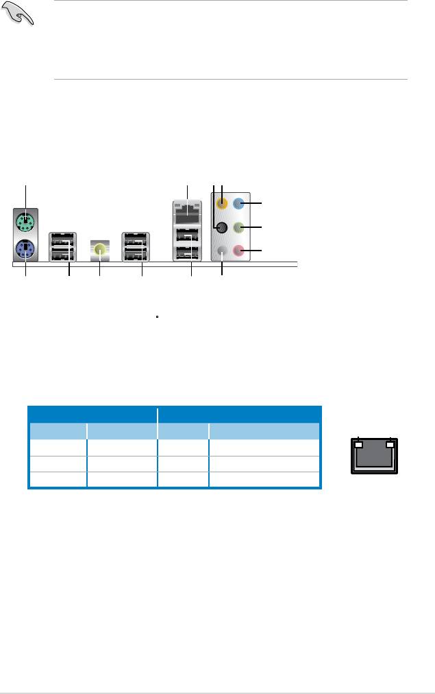
2.7.1 Rear panel connectors
1. PS/2 mouse port (green). This port is for a PS/2 mouse.
2. LAN (RJ-45) port.
Supported by Gigabit LAN controller, this port allows
Gigabit connection to a Local Area Network (LAN) through a network hub.
Refer to the table below for the LAN port LED indications.
ASUS P5QLD PRO 2-23
1
2
3
4
5
6
7
13 9
101112
8
LAN port LED indications
ACT/LINK LED SPEED LED
Status Description Status Description
OFF No link OFF 10 Mbps connection
YELLOW Linked ORANGE 100 Mbps connection
BLINKING Data activity GREEN 1 Gbps connection
3. Rear Speaker Out port (black). This port connects the rear speakers in a
4-channel, 6-channel, or 8-channel audio conguration.
4. Center/Subwoofer port (orange).
This port connects the center/subwoofer
speakers.
5. Line In port (light blue).
This port connects the tape, CD, DVD player, or
other audio sources.
6. Line Out port (lime).
This port connects a headphone or a speaker. In
4-channel, 6-channel, and 8-channel conguration, the function of this port
becomes Front Speaker Out.
ACT/LINK
SPEED
LED
LED
LAN port
• The USB device wake-up feature requires a power supply that can
provide 500mA on the +5VSB lead for each USB port; otherwise,
the system would not power up.
• The total current consumed must NOT exceed the power supply
capability (+5VSB) whether under normal condition or in sleep mode.
7. Microphone port (pink). This port connects a microphone.
8. Side Speaker Out port (gray).
This port connects the side speakers in an
8-channel audio conguration.
Refer to the audio conguration table on the next page for the function of the
audio ports in 2, 4, 6, or 8-channel conguration.
Audio 2, 4, 6, or 8-channel conguration
Headset
Port
4-channel 6-channel 8-channel
2-channel
Light Blue Line In Line In Line In Line In
Lime Line Out Front Speaker Out Front Speaker Out Front Speaker Out
Pink Mic In Mic In Mic In Mic In
Orange – – Center/Subwoofer Center/Subwoofer
Black – Rear Speaker Out Rear Speaker Ou Rear Speaker Out
Gray – – – Side Speaker Out
9. USB 2.0 ports 1 and 2.
These two 4-pin Universal Serial Bus (USB) ports
are available for connecting USB 2.0 devices.
10. USB 2.0 ports 3 and 4. These two 4-pin Universal Serial Bus (USB) ports
are available for connecting USB 2.0 devices.
11. Coaxial S/PDIF Out port. This port connects an external audio output device
via a coaxial S/PDIF cable.
12. USB 2.0 ports 5 and 6.
These two 4-pin Universal Serial Bus (USB) ports
are available for connecting USB 2.0 devices.
13.
PS/2 keyboard port (purple). This port is for a PS/2 keyboard.
2-24 Chapter 2: Hardware information
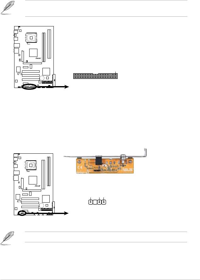
2.7.2 Internal connectors
1. Floppy disk drive connector (34-1 pin FLOPPY)
This connector is for the provided oppy disk drive (FDD) signal cable. Insert
one end of the cable to this connector, then connect the other end to the
signal connector at the back of the oppy disk drive.
Pin 5 on the connector is removed to prevent incorrect cable connection when
using a FDD cable with a covered Pin 5.
ASUS P5QLD PRO 2-25
P5QLD PRO
FLOPPY
PIN
1
NOTE:
Orient the red markings on
the floppy ribbon cable to PIN 1.
P5QLD PRO
Floppy Disk Drive Connector
2. Digital audio connector (4-1 pin SPDIF_OUT)
This connector is for an additional Sony/Philips Digital Interface (S/PDIF)
port(s). Connect the S/PDIF Out module cable to this connector, then install
the module to a slot opening at the back of the system chassis.
The S/PDIF module is purchased separately.
SPDIFOUT
P5QLD PRO
+5V
GND
SPDIF_OUT
P5QLD PRO
Digital Audio Connector
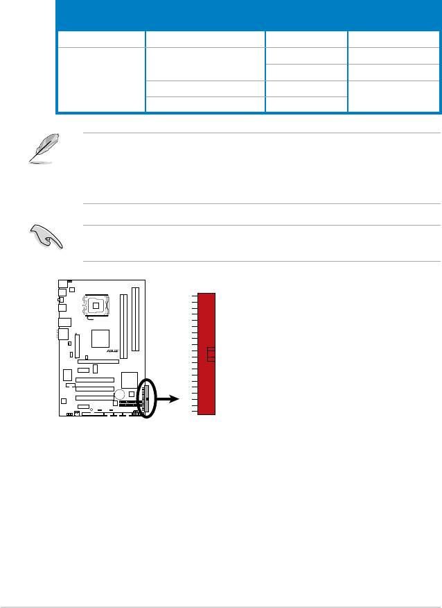
3. IDE connector (40-1 pin PRI_IDE)
The onboard IDE connector is for the Ultra DMA 133/100/66 signal cable.
There are three connectors on each Ultra DMA 133/100/66 signal cable:
blue, black, and gray. Connect the blue connector to the motherboard’s IDE
connector, then select one of the following modes to congure your device.
Mode of
Drive jumper setting
Cable connector
device(s)
Single device Cable-Select or Master - Black
Master Black
Cable-Select
Slave Gray
Two devices
Master Master
Black or gray
Slave Slave
• Pin 20 on the IDE connector is removed to match the covered hole on the
Ultra DMA cable connector. This prevents incorrect insertion when you
connect the IDE cable.
• Use the 80-conductor IDE cable for Ultra DMA 133/100/66 IDE devices.
If any device jumper is set as “Cable-Select,” make sure all other device
jumpers have the same setting.
2-26 Chapter 2: Hardware information
P5QLD PRO
PRI_IDE
P5QLD PRO
IDE Connector
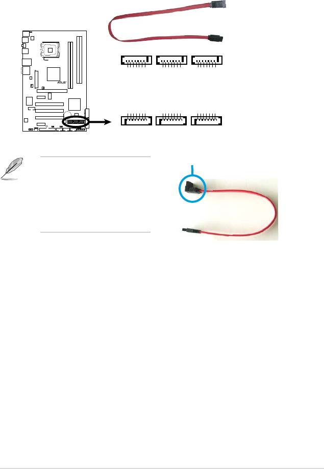
4. Serial ATA connectors (7-pin SATA1-6)
These connectors are for the Serial ATA signal cables for Serial ATA hard disk
drives.
right angle side
Connect the right-angle side
of SATA signal cable to SATA
device. Or you may connect the
right-angle side of SATA cable to
the onboard SATA port to avoid
mechanical conict with huge
graphics cards.
ASUS P5QLD PRO 2-27
SATA6
SATA4
SATA2
GND
GND
GND
GND
GND
GND
GND
GND
GND
A_RXN6
A_RXP6
A_RXN4
A_RXP4
A_RXN2
A_RXP2
RSATA_TXP6
RSATA_TXN6
RSAT
RSAT
RSATA_TXP4
RSATA_TXN4
RSAT
RSAT
RSATA_TXP2
RSATA_TXN2
RSAT
RSAT
P5QLD PRO
SATA5
SATA3
SATA1
A_RXP5
A_RXN5
A_TXN5
A_TXP5
A_RXP3
A_RXN3
A_TXN3
A_TXP3
A_RXP1
A_RXN1
A_TXN1
A_TXP1
AT
AT
AT
GND
RS
RSAT
GND
RSAT
RSAT
GND
GND
RS
RSAT
GND
RSAT
RSAT
GND
GND
RS
RSAT
GND
RSAT
RSAT
GND
P5QLD PRO
SATA Connectors
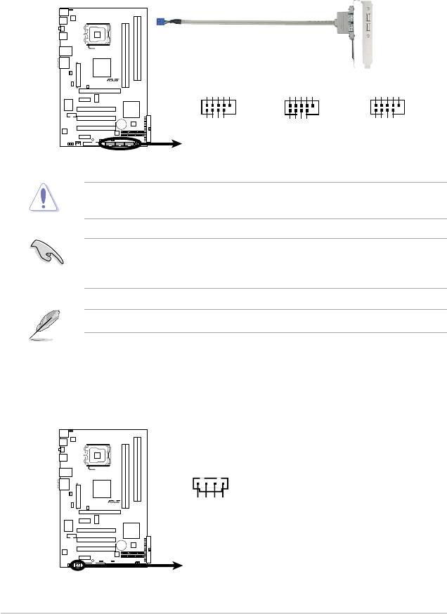
5. USB connectors (10-1 pin USB78, USB910, USB1112)
These connectors are for USB 2.0 ports. Connect the USB module cable
to any of these connectors, then install the module to a slot opening at the
back of the system chassis. These USB connectors comply with USB 2.0
specication that supports up to 480 Mbps connection speed.
Never connect a 1394 cable to the USB connectors. Doing so will damage the
motherboard!
You can connect the front panel USB cable to the ASUS Q-Connector (USB,
blue) rst, and then install the Q-Connector (USB) to the USB connector
onboard if your chassis supports front panel USB ports.
The USB module cable is purchased separately.
2-28 Chapter 2: Hardware information
-
+
-
+
P5QLD PRO
USB+5V
USB_P12
USB_P12
GND
NC
USB+5V
USB_P8-
USB_P8+
GND
NC
USB+5V
USB_P10
USB_P10
GND
NC
USB1112
USB78
USB910
1
1
1
GND
GND
GND
USB+5V
USB+5V
USB+5V
USB_P9-
USB_P11-
USB_P7-
USB_P9+
USB_P11+
USB_P7+
P5QLD PRO
USB 2.0 Connectors
6. Optical drive audio connector (4-pin CD)
These connectors allow you to receive stereo audio input from sound sources
such as a CD-ROM, TV tuner, or MPEG card.
CD
(black)
P5QLD PRO
und
o
Gr
Ground
udio Channel
udio Channel
A
A
t
t
Lef
Righ
P5QLD PRO Internal Audio Connector
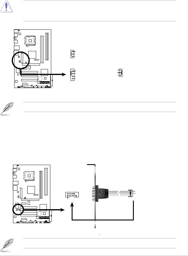
7. CPU, chassis, and power fan connectors
(4-pin CPU_FAN, 3-pin CHA_FAN, 3-pin PWR_FAN)
The fan connectors support cooling fans of 350 mA~2000 mA (24 W max.)
or a total of 1 A~7 A (84 W max.) at +12V. Connect the fan cables to the fan
connectors on the motherboard, making sure that the black wire of each
cable matches the ground pin of the connector.
Do not forget to connect the fan cables to the fan connectors. Insufcient air
ow inside the system may damage the motherboard components. These are
not jumpers! Do not place jumper caps on the fan connectors!
Only the 4-pin CPU_FAN connector supports the ASUS Q-FAN feature.
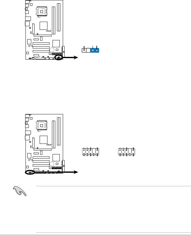
8. Serial port connector (10-1 pin COM1)
This connector is for a serial (COM) port. Connect the serial port module
cable to this connector, then install the module to a slot opening at the back
of the system chassis.
The serial port module is purchased separately.
ASUS P5QLD PRO 2-29
CHA_FAN
GND
+12V
Rotation
P5QLD PRO
CPU_FAN
PWR_FAN
GND
Rotation
CPU FAN PWR
+12V
CPU FAN IN
GND
CPU FAN PWM
P5QLD PRO
Fan Connectors
COM1
P5QLD PRO
PIN1
P5QLD PRO
COM Port Connector
9. Chassis intrusion connector (4-1 pin CHASSIS)
This connector is for a chassis-mounted intrusion detection sensor or switch.
Connect one end of the chassis intrusion sensor or switch cable to this
connector. The chassis intrusion sensor or switch sends a high-level signal to
this connector when a chassis component is removed or replaced. The signal
is then generated as a chassis intrusion event.
By default, the pin labeled “Chassis Signal” and “Ground” are shorted with
a jumper cap. Remove the jumper caps only when you intend to use the
chassis intrusion detection feature.
10. Front panel audio connector (10-1 pin AAFP)
This connector is for a chassis-mounted front panel audio I/O module that
supports either HD Audio or legacy AC`97 audio standard. Connect one end
of the front panel audio I/O module cable to this connector.
•
We recommend that you connect a high-denition front panel audio module
to this connector to avail of the motherboard’s high-denition audio capability.
•
If you want to connect a high-denition front panel audio module to this
connector, set the Front Panel Type item in the BIOS setup to [HD Audio];
if you want to connect an AC'97 front panel audio module to this connector,
set the item to [AC97]. By default, this connector is set to [HD Audio]. See
section 4.5.3 Onboard Devices Conguration for details.
2-30 Chapter 2: Hardware information
CHASSIS
P5QLD PRO
+5VSB_MB
Chassis Signal
GND
(Default)
P5QLD PRO
Intrusion Connector
AAFP
HD-audio-compliant
Legacy AC’97
pin definition
compliant definition
P5QLD PRO
GND
PRESENSE#
SENSE1_RETUR
SENSE2_RETUR
AGND
NC
NC
NC
NC
MIC2
PORT1L
PORT1R
PORT2R
PORT2L
MICPWR
Line out_R
Line out_L
SEBSE_SEND
P5QLD PRO
Front Panel Audio Connector
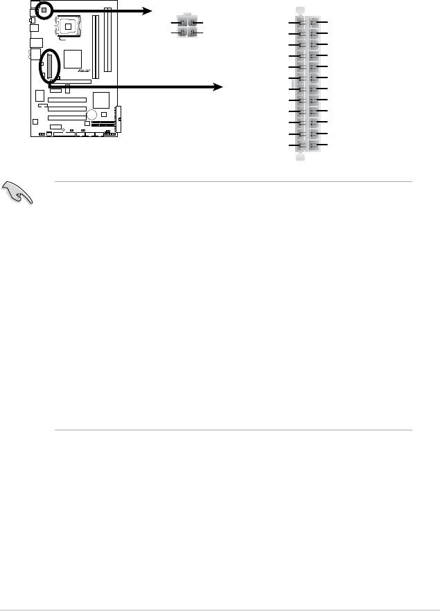
11. ATX power connectors (24-pin EATXPWR, 4-pin EATX12V)
These connectors are for ATX power supply plugs. The power supply plugs
are designed to t these connectors in only one orientation. Find the proper
orientation and push down rmly until the connectors completely t.
•
For a fully congured system, we recommend that you use a power supply
unit (PSU) that complies with ATX 12 V Specication 2.0 (or later version)
and provides a minimum power of 400 W.
• Do not forget to connect the 4-pin EATX12V power plug; otherwise, the
system will not boot.
• Use of a PSU with a higher power output is recommended when
conguring a system with more power-consuming devices. The system
may become unstable or may not boot up if the power is inadequate.
• The ATX 12 V Specication 2.0-compliant (400W) PSU has been tested
to support the motherboard power requirements with the following
conguration:
®
®
CPU: Intel
Pentium
Extreme 3.73GHz
Memory: 512 MB DDR2 (x4)
Graphics card: ASUS EAX1900XT
Parallel ATA device: IDE hard disk drive
Serial ATA device: SATA hard disk drive (x2)
Optical drive: DVD-RW
ASUS P5QLD PRO 2-31
ATX12V
EATXPWR
+12V DC
+12V DC
+3 Volts
+3 Volts
GND
GND
-12 Volts
+3 Volts
Ground
Ground
PSON#
+5 Volts
Ground
Ground
P5QLD PRO
Ground
+5 Volts
Ground
Ground
-5 Volts
Power OK
+5 Volts
+5V Standby
+5 Volts
+12 Volts
+5 Volts
+12 Volts
Ground
+3 Volts
P5QLD PRO ATX Power Connector
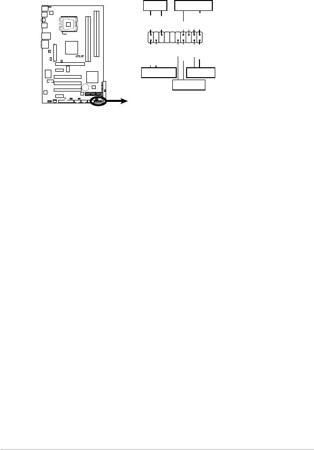
12. System panel connector (20-8 pin PANEL)
This connector supports several chassis-mounted functions.
• System power LED (2-pin PLED)
This 2-pin connector is for the system power LED. Connect the chassis
power LED cable to this connector. The system power LED lights up when
you turn on the system power, and blinks when the system is in sleep mode.
•
Hard disk drive activity LED (2-pin IDE_LED)
This 2-pin connector is for the HDD Activity LED. Connect the HDD Activity
LED cable to this connector. The IDE LED lights up or ashes when data is
read from or written to the HDD.
•
System warning speaker (4-pin SPEAKER)
This 4-pin connector is for the chassis-mounted system warning speaker.
The speaker allows you to hear system beeps and warnings.
•
ATX power button/soft-off button (2-pin PWRSW)
This connector is for the system power button. Pressing the power button
turns the system on or puts the system in sleep or soft-off mode depending
on the BIOS settings. Pressing the power switch for more than four seconds
while the system is ON turns the system OFF.
•
Reset button (2-pin RESET)
This 2-pin connector is for the chassis-mounted reset button for system
reboot without turning off the system power.
2-32 Chapter 2: Hardware information
PANEL
PLED SPEAKER
Ground
Ground
Speaker
PLED+
PLED-
+5V
IDE_LED+
IDE_LED-
PWR
Ground
Reset
Ground
P5QLD PRO
+IDE_LED
RESET
PWRSW
*
Requires an ATX power supply
P5QLD PRO
System Panel Connector
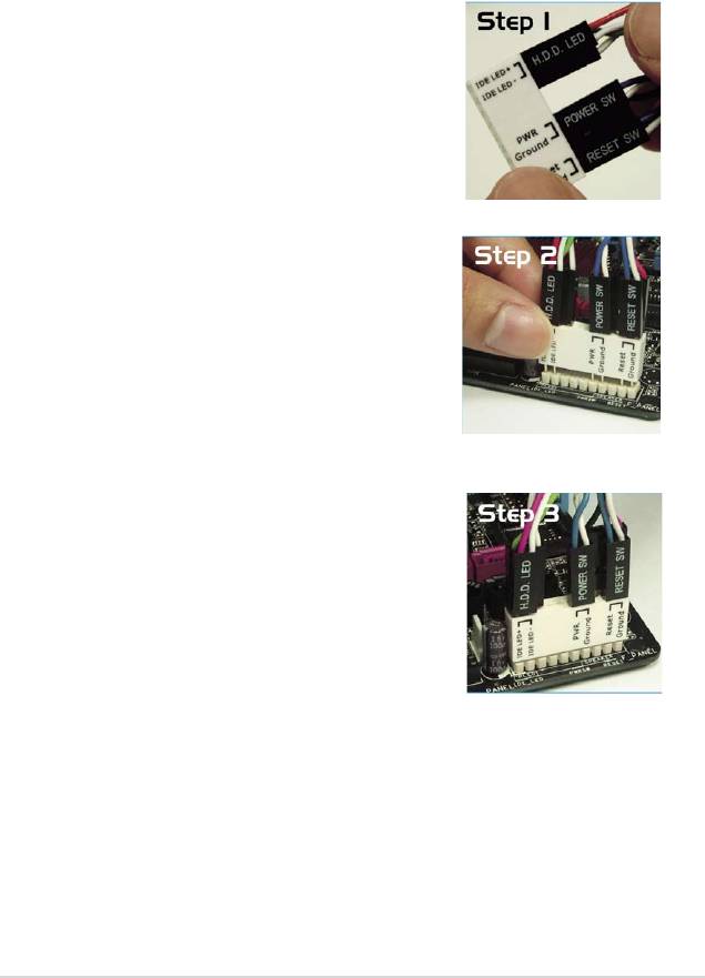
Q-Connector (system panel)
You can use ASUS Q-Connector to connect / disconnect chassis front panel
cables by only a few steps. Directions below shows how to install ASUS
Q-Connector.
Step1.
Connect correct front panel to ASUS
Q-Connector rst. You can refer to the
marking on Q-Connector itself to know the
detail pin denition.
Step2.
Properly install the ASUS Q-Connector to the
System panel connctor.
Step3.
Front panel functions are enabled.
ASUS P5QLD PRO 2-33

2-34 Chapter 2: Hardware information
