Asus P5K: Software
Software: Asus P5K
This chapter describes the contents
of the support CD that comes with the
motherboard package.
Software
5
support

Chapter summary
5
5.1 Installing an operating system ................................................... 5-1
5.2 Support CD information ..............................................................
5-1
5.3 Software information ...................................................................
5-9
5.4 RAID congurations ..................................................................
5-28
5.5 Creating a RAID driver disk .......................................................
5-37
ASUS P5K
5.1 Installing an operating system
®
This motherboard supports Windows
XP/64-bit XP/Vista/64-bit Vista operating
systems (OS). Always install the latest OS version and corresponding updates to
maximize the features of your hardware.
• Motherboard settings and hardware options vary. Use the setup
procedures presented in this chapter for reference only. Refer to your OS
documentation for detailed information.
®
®
• Make sure that you install Windows
2000 Service Pack 4 or the Windows
XP Service Pack2 or later versions before installing the drivers for better
compatibility and system stability.
5.2 Support CD information
The support CD that came with the motherboard package contains the drivers,
software applications, and utilities that you can install to avail all motherboard
features.
The contents of the support CD are subject to change at any time without
notice. Visit the ASUS website(www.asus.com) for updates.
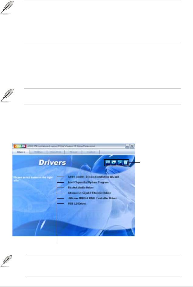
5.2.1 Running the support CD
Place the support CD to the optical drive. The CD automatically displays the
Drivers menu if Autorun is enabled in your computer.
Click an icon to
display support
CD/motherboard
information
Click an item to install
If Autorun is NOT enabled in your computer, browse the contents of the support
CD to locate the le ASSETUP.EXE from the BIN folder. Double-click the
ASSETUP.EXE to run the CD.
ASUS P5K 5-1

5.2.2 Drivers menu
The drivers menu shows the available device drivers if the system detects installed
devices. Install the necessary drivers to activate the devices.
ASUS InstAll-Drivers Installation Wizard
Installs the ASUS InstAll-Drivers Installation Wizard.
Intel Chipset Inf Update Program
®
Installs the Intel
chipset Inf update program.
Realtek Audio Driver
®
Installs the Realtek
ALC883 audio driver and application.
Attansic L1 Gigabit Ethernet Driver
Installs the Attansic L1 Gigabit Ethernet LAN driver.
JMicron JMB36X RAID Controller Driver
®
Installs the JMicron
JMB363 Serial ATA RAID controller driver.
USB 2.0 Driver
Installs the Universal Serial Bus 2.0 (USB 2.0) driver.
5-2 Chapter 5: Software support

5.2.3 Utilities menu
The Utilities menu shows the applications and other software that the motherboard
supports.
ASUS InstAll-Installation Wizard for Utilities
Installs all of the utilities through the Installation Wizard.
ASUS Update
Allows you to download the latest version of the BIOS from the ASUS website.
Before using the ASUS Update, make sure that you have an Internet connection
so you can connect to the ASUS website.
ASUS PC Probe II
This smart utility monitors the fan speed, CPU temperature, and system voltages,
and alerts you of any detected problems. This utility helps you keep your computer
in healthy operating condition.
ASUS AI Suite
Installs the ASUS AI Suite.
ASUS P5K 5-3

You can also install the following utilities from the ASUS Superb Software
Library CD.
ADOBE Acrobat Reader V7.0
®
®
Installs the Adobe
Acrobat
Reader that allows you to open, view, and print
documents in Portable Document Format (PDF).
Microsoft DirectX 9.0c
®
®
Installs the Microsoft
DirectX 9.0 driver. The Microsoft DirectX
9.0 is a multimedia
®
technology that enhances computer graphics and sound. DirectX
improves the
multimedia features of you computer so you can enjoy watching TV and movies,
capturing videos, or playing games in your computer. Visit the Microsoft website
(www.microsoft.com) for updates.
Symantec Norton Internet Security
The anti-virus application detects and protects your computer from viruses that
destroys data.
WinDVD Copy5 Trial
Installs the WinDVD Copy5 Trial version.
Corel Snapre Plus SE
Installs the Corel Snapre Plus SE software.
5-4 Chapter 5: Software support

5.2.4 Make Disk menu
®
The Make Disk menu contains items to create JMicron
JMB363 RAID driver disk.
JMicron JMB36X 32/64bit RAID Driver
®
Allows you to create a JMicron
JMB363 32/64bit RAID driver.
ASUS P5K 5-5
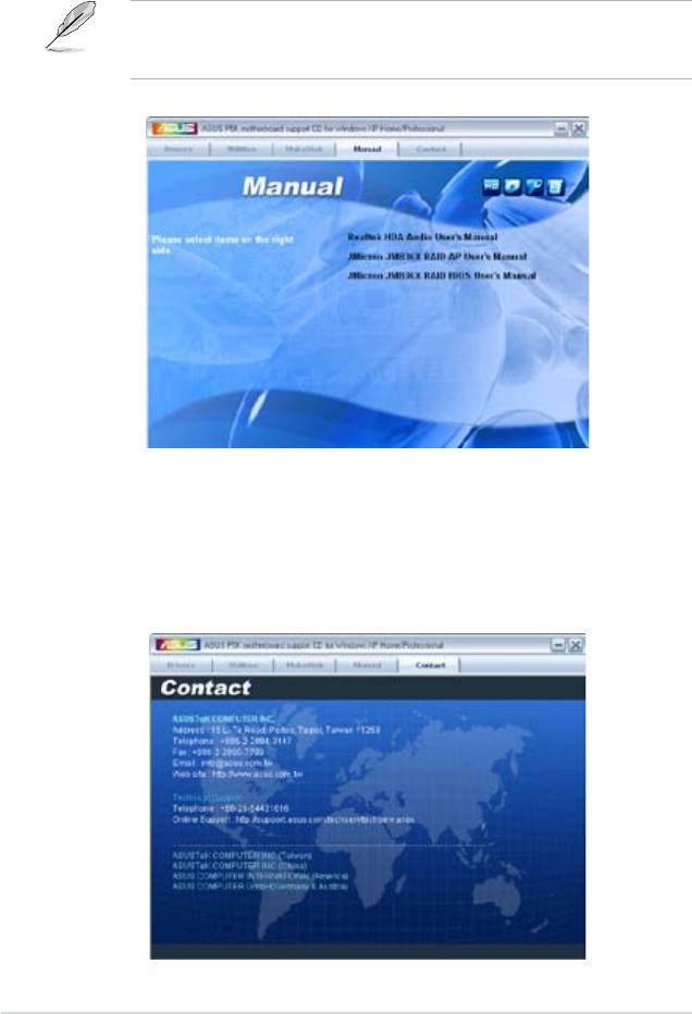
5.2.5 Manual menu
The Manual menu contains a list of supplementary user manuals. Click an item to
open the folder of the user manual.
Most user manual les are in Portable Document Format (PDF). Install the
®
®
Adobe
Acrobat
Reader from the ASUS Superb Software Library CD before
opening a user manual le.
5.2.6 ASUS Contact information
Click the Contact tab to display the ASUS contact information. You can also nd
this information on the inside front cover of this user guide.
5-6 Chapter 5: Software support
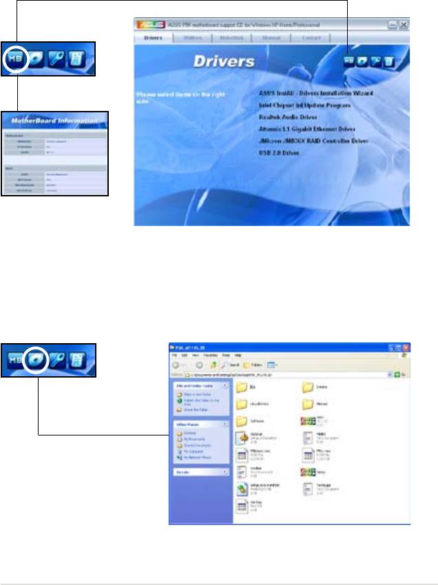
5.2.7 Other information
The icons on the top right corner of the screen give additional information on the
motherboard and the contents of the support CD. Click an icon to display the
specied information.
Motherboard Info
Displays the general specications of the motherboard.
Browse this CD
Displays the support CD contents in graphical format.
ASUS P5K 5-7
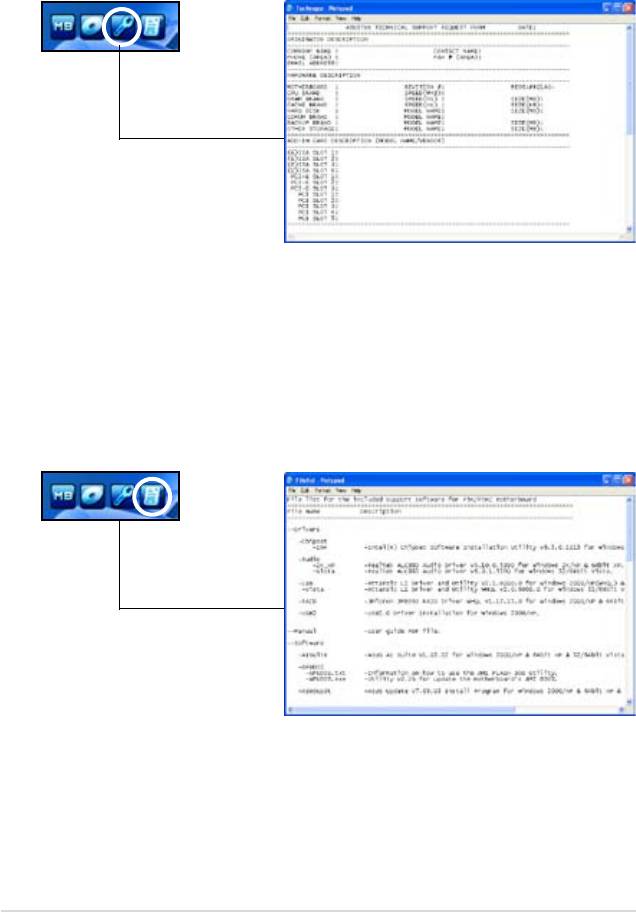
Technical support Form
Displays the ASUS Technical Support Request Form that you have to ll out when
requesting technical support.
Filelist
Displays the contents of the support CD and a brief description of each in text
format.
5-8 Chapter 5: Software support
5.3 Software information
Most of the applications in the Support CD have wizards that will conveniently
guide you through the installation. View the online help or readme le that came
with the software application for more information.
5.3.1 ASUS MyLogo2™
The ASUS MyLogo2™ utility lets you customize the boot logo. The boot logo is the
image that appears on screen during the Power-On Self-Tests (POST). The ASUS
MyLogo2™ is automatically installed when you install the ASUS Update utility from
the Support CD. See section “5.2.3 Utilities menu” for details.
• Before using the ASUS MyLogo2™, use the AFUDOS utility to make a copy
of your original BIOS le, or obtain the latest BIOS version from the ASUS
website. See section 4.1.4 AFUDOS utility.
• Make sure that the BIOS item Full Screen Logo is set to [Enabled] if
you wish to use ASUS MyLogo2. See section 4.6.2 Boot Settings
Conguration.
• You can create your own boot logo image in GIF, or BMP le formats.
• The le size should be smaller than 150 K.
To launch the ASUS MyLogo2™:
1. Launch the ASUS Update utility. Refer to section “4.1.1 ASUS Update utility”
for details.
2. Select
Options from the drop down menu, then click Next.
3. Check the option
Launch MyLogo to replace system boot logo before
ashing BIOS, then click Next.
4. Select
Update BIOS from a le from the drop down menu, then click Next.
5. When prompted, locate the new
BIOS le, then click Next. The ASUS
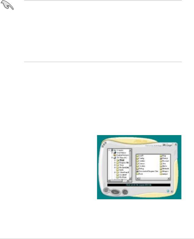
MyLogo window appears.
6. From the left window pane, select the
folder that contains the image you
intend to use as your boot logo.
ASUS P5K 5-9

7. When the logo images appear on the
right window pane, select an image to
enlarge by clicking on it.
8. Adjust the boot image to your desired
size by selecting a value on the Ratio
box.
9. When the screen returns to the ASUS Update utility, ash the original BIOS to
load the new boot logo.
10. After ashing the BIOS, restart the computer to display the new boot logo
during POST.
5-10 Chapter 5: Software support
5.3.2 Audio congurations
®
The Realtek
ALC883 audio CODEC provides 8-channel audio capability to deliver
the ultimate audio experience on your computer. The software provides Jack-
Sensing function, S/PDIF Out support, and interrupt capability. The ALC883 also
®
®
includes the Realtek
proprietary UAJ
(Universal Audio Jack) technology for all
audio ports, eliminating cable connection errors and giving users plug and play
convenience.
®
Follow the installation wizard to install the Realtek
Audio Driver from the support
CD that came with the motherboard package.
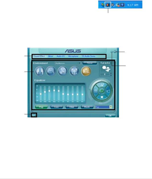
If the Realtek audio software is correctly installed, you will nd the Realtek HD
Audio Manager icon on the taskbar.
From the taskbar, double-click on the SoundEffect
icon to display the Realtek HD Audio Manager.
Realtek HD Audio Manager
Realtek HD Audio Manager
Exit button
Conguration
options
Minimize
button
Control settings
window
Information
button
ASUS P5K 5-11
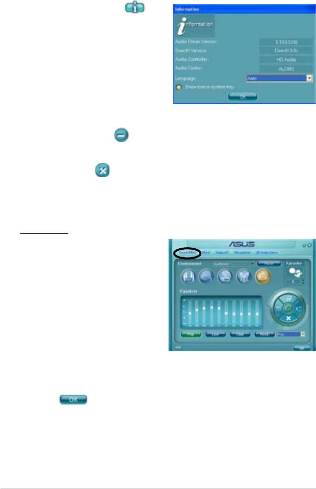
Information
Click the information button ( ) to
display information about the audio driver
version, DirectX version, audio controller,
audio codec, and language setting.
Minimize
Click the minimize button ( ) to minimize the window.
Exit
Click the exit button ( ) to exit the Realtek HD Audio Manager.
Conguration options
Click any of the tabs in this area to congure your audio settings.
Sound Effect
®
The Realtek
ALC883 Audio CODEC
allows you to set your listening
environment, adjust the equalizer, set
the karaoke, or select pre-programmed
equalizer settings for your listening
pleasure.
To set the sound effect options:
1. From the Realtek HD Audio
Manager, click the Sound Effect
tab.
2. Click the shortcut buttons or the drop-down menus for options on changing
the acoustic environment, adjust the equalizer, or set the karaoke to your
desired settings.
3. Click
to effect the Sound Effect settings and exit.
5-12 Chapter 5: Software support
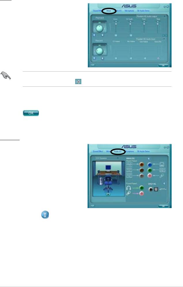
Mixer
The Mixer option allows you to congure
audio output (playback) volume and
audio input (record) volume.
To set the mixer options:
1. From the Realtek HD Audio
Manager, click the Mixer tab.
2. Turn the volume buttons to adjust
the Playback and/or Record
volume.
The Mixer option activates voice input from all channels by default. Make sure
to set all channels to mute ( ) if you do not want voice input.
3. Make adjustments to Wave, SW Synth, Front, Rear, Subwoofer, CD volume,
Mic volume, Line Volume, and Stereo mix by clicking the control tabs and
dragging them up and down until you get the desired levels.
4. Click
to effect the Mixer settings and exit.
Audio I/O
The Audio I/O option allows you
congure your input/output settings.
To set the Audio I/O options:
1. From the Realtek HD Audio
Manager, click the Audio I/O tab.
2. Click the drop-down menu to
select the channel conguration.
3. The control settings window
displays the status of connected
devices. Click for analog and digital options.
4. Click <OK> to effect the Audio I/O settings and exit
ASUS P5K 5-13
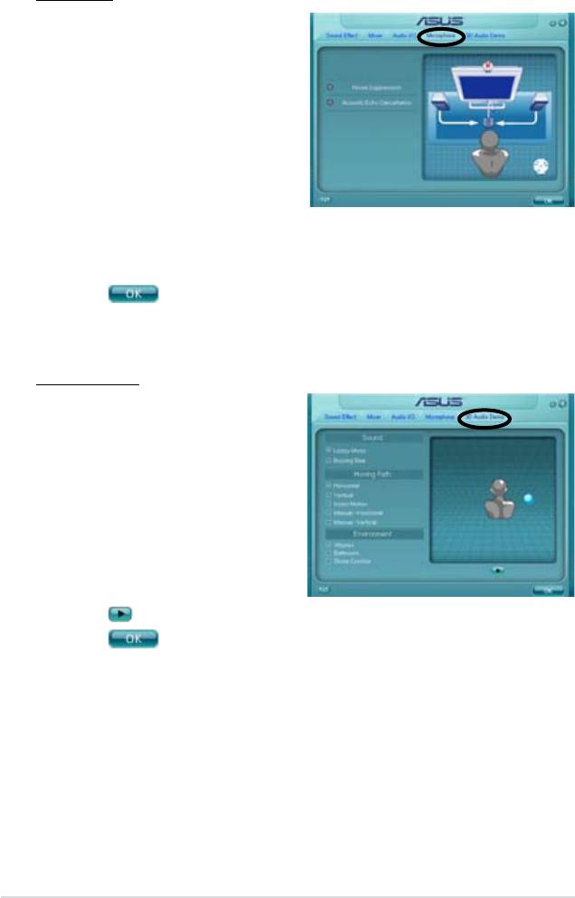
Microphone
The Microphone option allows you
congure your input/output settings
and to check if your audio devices are
connected properly.
To set the Microphone options:
1. From the Realtek HD Audio
Manager, click the Microphone
tab.
2. Click the Noise Suppression
option button to reduce the static background noise when recording.
3. Click the Acoustic Echo Cancellation option button to reduce the echo from
the front speakers when recording.
4. Click
to effect the Microphone settings and exit.
3D Audio Demo
The 3D Audio Demo option gives you a
demonstration of the 3D audio feature.
To start the 3D Audio Demo:
1. From the Realtek HD Audio
Manager, click the 3D Audio
Demo tab.
2. Click the option buttons to change
the sound, moving path, or
environment settings.
3. Click
to test your settings.
4. Click
to effect the 3D Audio Demo settings and exit.
5-14 Chapter 5: Software support
5.3.3 ASUS PC Probe II
PC Probe II is a utility that monitors the computer’s vital components, and detects
and alerts you of any problem with these components. PC Probe II senses fan
rotations, CPU temperature, and system voltages, among others. Because PC
Probe II is software-based, you can start monitoring your computer the moment
you turn it on. With this utility, you are assured that your computer is always at a
healthy operating condition.
Installing PC Probe II
To install PC Probe II on your computer:
1. Place the Support CD to the optical drive. The Drivers installation tab appears
if your computer has an enabled Autorun feature.
If Autorun is not enabled in your computer, browse the contents of the Support
CD to locate the setup.exe le from the ASUS PC Probe II folder. Double-click
the setup.exe le to start installation.
2. Click the Utilities tab, then click ASUS PC Probe II.
3. Follow the screen instructions to complete installation.
Launching PC Probe II
You can launch the PC Probe II right after installation or anytime from the
®
Windows
desktop.
®
To launch the PC Probe II from the Windows
desktop, click Start > All Programs
> ASUS > PC Probe II > PC Probe II v1.xx.xx. The PC Probe II main window
appears.
®
After launching the application, the PC Probe II icon appears in the Windows
taskbar. Click this icon to close or restore the application.
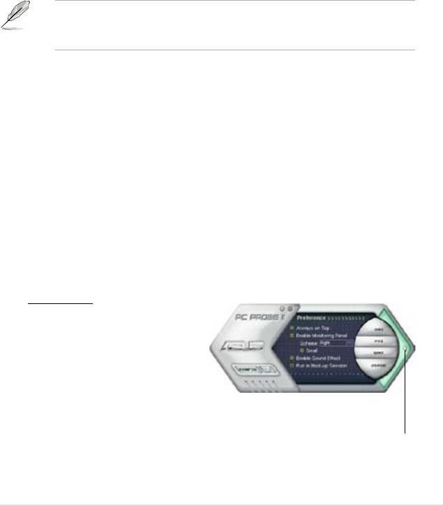
Using PC Probe II
Main window
The PC Probe II main window
allows you to view the current
status of your system and change
the utility conguration. By
default, the main window displays
the Preference section. You can
close or restore the Preference
section by clicking on the triangle on the main window right handle.
Click to close the
Preference panel
ASUS P5K 5-15
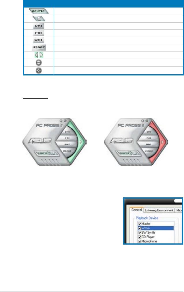
Button Function
Opens the Conguration window
Opens the Report window
Opens the Desktop Management Interface window
Opens the Peripheral Component Interconnect window
Opens the Windows Management Instrumentation window
Opens the hard disk drive, memory, CPU usage window
Shows/Hides the Preference section
Minimizes the application
Closes the application
Sensor alert
When a system sensor detects a problem, the main window right handle
turns red, as the illustrations below show.
When displayed, the monitor panel for that sensor also turns red. Refer to the
Monitor panels section for details.
Preferences
You can customize the application using the
Preference section in the main window. Click
the box before each preference to activate or
deactivate.
5-16 Chapter 5: Software support
Hardware monitor panels
The hardware monitor panels display the current value of a system sensor such as
fan rotation, CPU temperature, and voltages.
The hardware monitor panels come in two display modes: hexagonal (large) and
rectangular (small). When you check the Enable Monitoring Panel option from the
Preference section, the monitor panels appear on your computer’s desktop.
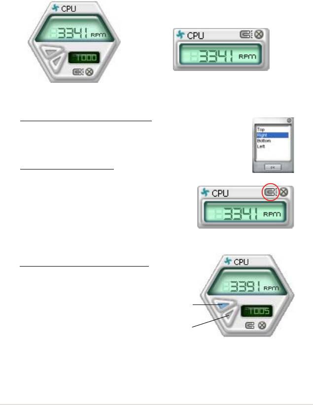
Small display
Large display
Changing the monitor panels position
To change the position of the monitor panels in the desktop,
click the arrow down button of the Scheme options, then select
another position from the list box. Click OK when nished.
Moving the monitor panels
All monitor panels move together using a magnetic effect. If
you want to detach a monitor panel from
the group, click the horseshoe magnet
icon. You can now move or reposition the
panel independently.
Adjusting the sensor threshold value
You can adjust the sensor threshold
value in the monitor panel by
Click to
clicking the or buttons. You can
increase
also adjust the threshold values
value
using the Cong window.
Click to
You cannot adjust the sensor
decrease
threshold values in a small
value
monitoring panel.
ASUS P5K 5-17
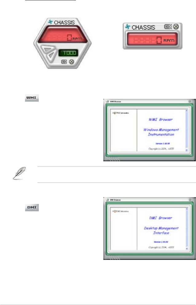
Monitoring sensor alert
The monitor panel turns red when a component value exceeds or is lower
than the threshold value. Refer to the illustrations below.
Small display
Large display
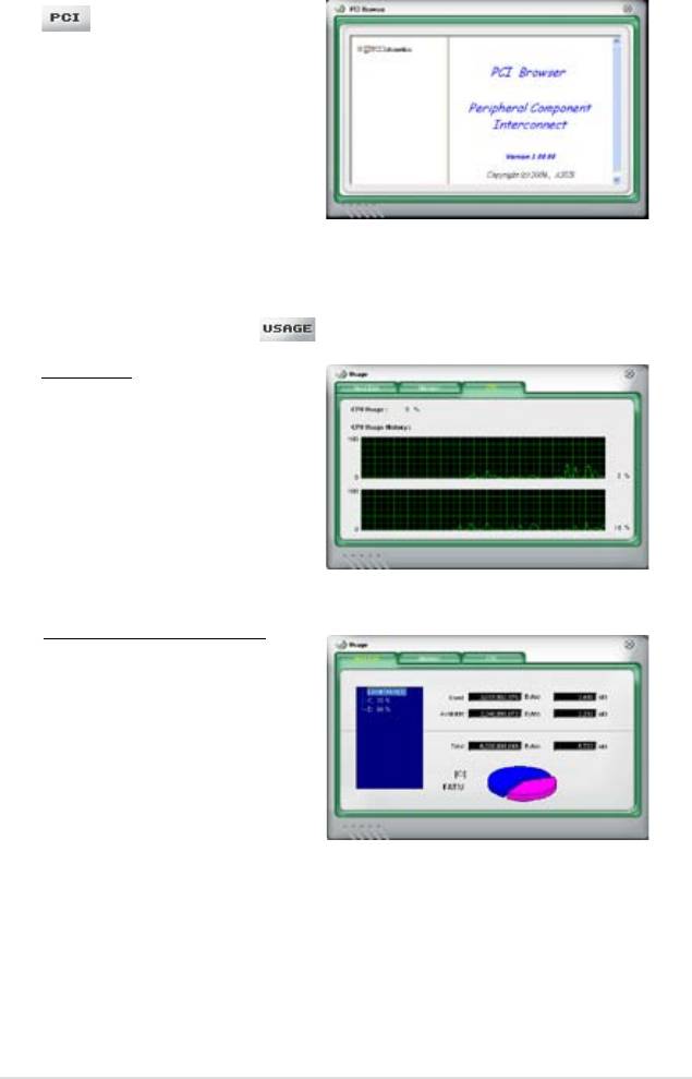
WMI browser
Click to display the
WMI (Windows Management
Instrumentation) browser. This
browser displays various Windows®
management information. Click an
item from the left panel to display on
the right panel. Click the plus sign (+)
before WMI Information to display the
available information.
You can enlarge or reduce the browser size by dragging the bottom right corner
of the browser.
DMI browser
Click to display the DMI
(Desktop Management Interface)
browser. This browser displays various
desktop and system information.
Click the plus sign (+) before DMI
Information to display the available
information.
5-18 Chapter 5: Software support
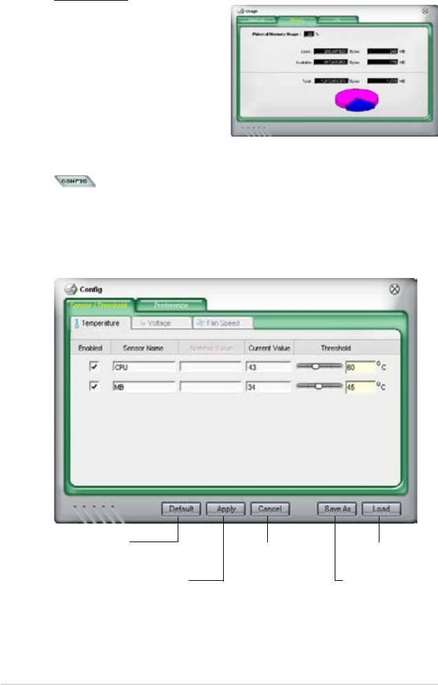
PCI browser
Click to display the PCI
(Peripheral Component Interconnect)
browser. This browser provides
information on the PCI devices installed
on your system. Click the plus sign
(+) before the PCI Information item to
display available information.
Usage
The Usage browser displays real-time information on the CPU, hard disk drive
space, and memory usage. Click to display the Usage browser.
CPU usage
The CPU tab displays real-
time CPU usage in line graph
representation. If the CPU has
an enabled Hyper-Threading,
two separate line graphs display
the operation of the two logical
processors.
Hard disk drive space usage
The Hard Disk tab displays the
used and available hard disk
drive space. The left panel of the
tab lists all logical drives. Click
a hard disk drive to display the
information on the right panel.
The pie chart at the bottom of
the window represents the used
(blue) and the available HDD
space.
ASUS P5K 5-19
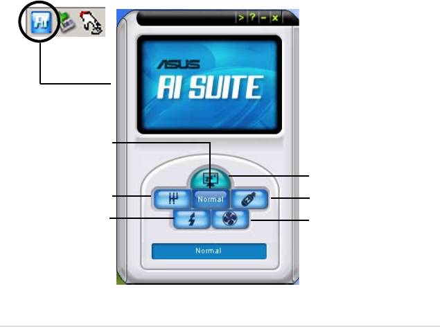
Memory usage
The Memory tab shows both
used and available physical
memory. The pie chart at the
bottom of the window represents
the used (blue) and the available
Conguring PC Probe II
Click to view and adjust the sensor threshold values.
The Cong window has two tabs: Sensor/Threshold and Preference. The Sensor/
Threshold tab enables you to activate the sensors or to adjust the sensor threshold
values. The Preference tab allows you to customize sensor alerts, or change the
temperature scale.
Loads the default
threshold values for
Cancels or
Loads your saved
each sensor
ignores your
conguration
changes
Applies your
Saves your
changes
conguration
5-20 Chapter 5: Software support
5.3.4 ASUS AI Suite
ASUS AI Suite allows you to launch AI Gear2, AI N.O.S., AI Booster, AI Nap, and
Q-Fan2 utilities easily.
Installing AI Suite
To install AI Suite on your computer:
1. Place the support CD to the optical drive. The Drivers installation tab appears
if your computer has an enabled Autorun feature.
2. Click the Utilities tab, then click
AI Suite.
3. Follow the screen instructions to complete installation.
Launching AI Suite
®
You can launch the AI Suite right after installation or anytime from the Windows
desktop.
®
To launch the AI Suite from the Windows
desktop, click Start > All Programs >
ASUS > AI Suite > AI Suite v1.xx.xx. The AI Suite main window appears.
®
After launching the application, the AI Suite icon appears in the Windows
taskbar.
Click this icon to close or restore the application.
Using AI Suite
Click the AI N.O.S., AI Gear2, AI Nap, AI Booster, or Q-Fan2 icon to launch the
utility, or click the Normal icon to restore the system to normal state.
Press to restore to normal
Press to launch AI Nap
Press to launch AI Gear2
Press to launch AI N.O.S.
Press to launch AI Booster
Press to launch Q-Fan2
ASUS P5K 5-21

Other feature buttons
Click on right corner of the main window to open the monitor window.
Displays the CPU/
system temperature,
CPU/memory/PCIE
voltage, and CPU/
chassis fan speed
Displays the FSB/CPU
frequency
Click on right corner of the expanded window to switch the temperature from
degrees Centigrade to degrees Fahrenheit.
5-22 Chapter 5: Software support

5.3.5 ASUS AI Gear2
ASUS AI Gear2 provides four system performance options that allows you to select
the best performance setting for your computing needs. This easy-to-use utility
adjusts the processor frequency and vCore voltage to minimize system noise and
power consumption.
After installing AI Suite from the bundled support CD, you can launch AI Gear2 by
double-clicking the AI Suite icon on your Windows OS taskbar and then click the AI
Gear2 button on the AI Suite main window.
Shift the gear to the performance setting that you like.
Maximum
Medium
Performance
Performance
High
Maximum
Performance
Power Saving
ASUS P5K 5-23

5.3.6 ASUS AI Nap
This feature allows you to minimize the power consumption of your computer
whenever you are away. Enable this feature for minimum power consumption and
a more quiet system operation.
After installing AI Suite from the bundled support CD, you can launch the utility by
double-clicking the AI Suite icon on the Windows OS taskbar and click the AI Nap
button on the AI Suite main window.
Click Yes on the conrmation screen.
To exit AI Nap mode, press the system power or mouse button then click Yes on
the conrmation screen.
To switch the power button functions from AI Nap to shutting down, just right
click the AI Suite icon on the OS taskbar, select AI Nap and click Use power
button. Unclick the the item to switch the function back.
5-24 Chapter 5: Software support
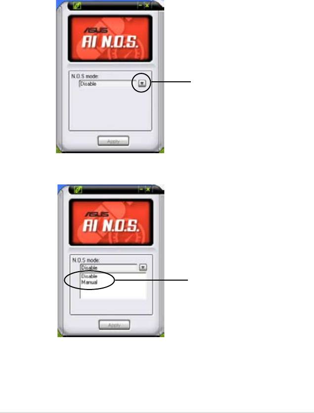
5.3.7 ASUS AI N.O.S.
This ASUS Non-delay Overclocking System feature intelligently determines the
system load and automatically boosts the performance for the most demanding
tasks.
After installing AI Suite from the bundled support CD, you can launch the utility
by double-clicking the AI Suite icon on the Windows OS taskbar and click the AI
N.O.S. button on the AI Suite main window.
drop-down menu
button
Click the drop-down menu button and select Disable or Manual.
select an N.O.S.
mode
Click Apply at the bottom to save the conguration.
ASUS P5K 5-25
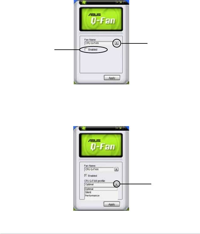
5.3.8 ASUS Q-Fan2
This ASUS Q-Fan2 Control feature allows you to set the appropriate performance
level of the CPU Q-Fan2 or the Chassis Q-Fan2 for more efcient system
operation. After enabling the Q-Fan2 function, the fans can be set to automatically
adjust depending on the temperature, to decrease fan speed, or to achieve the
maximum fan speed.
After installing AI Suite from the bundled support CD, you can launch the utility by
®
double-clicking the AI Suite icon on the Windows
OS taskbar and click the Q-Fan2
button on the AI Suite mAIn window.
Click the drop-down menu button and display the fan names. Select CPU Q-Fan2
or CHASSIS Q-Fan2. Click the box of Enable Q-Fan2 to activate this function.
drop-down list
Enable Q-
button
Fan2 box
Prole list appears after clicking the Enable Q-Fan2 box. Click the drop-down
list button and select a prole. Optimal mode makes the fans adjust speed
with the temperature; Silent mode minimizes fan speed for quiet fan operation;
Performance mode boosts the fan to achieve maximal fan speed for the best
cooling effect.
click to display the drop-
down list and select a
Q-Fan2 mode
Click Apply at the bottom to save the setup.
5-26 Chapter 5: Software support
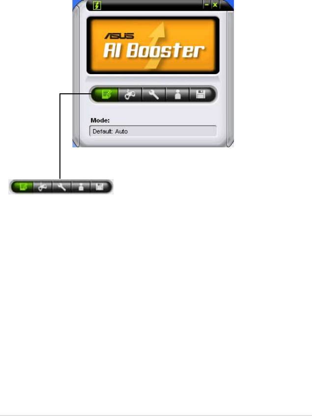
5.3.9 ASUS AI Booster
The ASUS AI Booster application allows you to overclock the CPU speed in
®
WIndows
environment without the hassle of booting the BIOS.
After installing AI Suite from the bundled support CD, you can launch the utility
®
by double-clicking the AI Suite icon on the Windows
OS taskbar and click the AI
Booster button on the AI Suite main window.
The options on the taskbar allow you to use the default settings, adjust CPU/
Memory/PCI-E frequency manually, or create and apply your personal overclocking
congurations.
ASUS P5K 5-27

5.4 RAID congurations
®
The motherboard comes with the JMicron
JMB363 RAID controller that allows you
to congure Serial ATA hard disk drives as RAID sets. The motherboard supports
the following RAID congurations.
RAID 0
(Data striping) optimizes two identical hard disk drives to read and write
data in parallel, interleaved stacks. Two hard disks perform the same work as a
single drive but at a sustained data transfer rate, double that of a single disk alone,
thus improving data access and storage. Use of two new identical hard disk drives
is required for this setup.
RAID 1
(Data mirroring) copies and maintains an identical image of data from one
drive to a second drive. If one drive fails, the disk array management software
directs all applications to the surviving drive as it contains a complete copy of
the data in the other drive. This RAID conguration provides data protection and
increases fault tolerance to the entire system. Use two new drives or use an
existing drive and a new drive for this setup. The new drive must be of the same
size or larger than the existing drive.
JBOD
(Spanning) stands for Just a Bunch of Disks and refers to hard disk drives
that are not yet congured as a RAID set. This conguration stores the same data
redundantly on multiple disks that appear as a single disk on the operating system.
Spanning does not deliver any advantage over using separate disks independently
and does not provide fault tolerance or other RAID performance benets.
If you want to boot the system from a hard disk drive included in a created RAID
set, copy rst the RAID driver from the support CD to a oppy disk before you
install an operating system to the selected hard disk drive. Refer to section “5.5
Creating a RAID driver disk” for details.
5.4.1 Installing Serial ATA hard disks
The motherboard supports Serial ATA hard disk drives. For optimal performance,
install identical drives of the same model and capacity when creating a disk array.
To install the SATA hard disks for a RAID conguration:
1. Install the SATA hard disks into the drive bays.
2. Connect the SATA signal cables.
3. Connect a SATA power cable to the power connector on each drive.
5-28 Chapter 5: Software support
®
5.4.2 JMicron
RAID Conguration
®
The JMicron
Serial ATA controller allows you to congure RAID 0, RAID 1 and
JBOD sets on the external Serial ATA hard disk drives.
Before creating a RAID set
Prepare the following items:
1. Two SATA HDDs, preferably with the same model and capacity.
®
2. A write-enabled oppy disk for
Windows
XP or a oppy disk/USB device for
®
Windows
Vista.
®
®
®
3. Microsoft
Windows
OS installation disk (Windows
XP/Vista)
4. Motherboard support CD with JMB363 driver
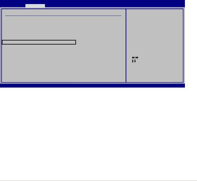
Complete the following steps before you create a RAID set:
1. Install the external Serial ATA hard disk drives (HDDs) on your system.
2. Set the
J-Micron eSATA/PATA Controller Mode
item in the BIOS to [RAID].
See section “4.4.5 Onboard Devices Conguration” for details.
BIOS SETUP UTILITY
Advanced
Onboard Device Conguraiton
Enable or Disable
High Denition Audio
Controller
High Denition Audio [Enabled]
Front Panel Type [HD Audio]
Onboard 1394 Controller [Enabled]
Onboard PCIE GbE LAN [Enabled]
LAN Option ROM [Disabled]
J-Micron eSATA/PATA Controller [Enabled]
Controller Mode [IDE]
Serial Port1 Address [3F8/IRQ4]
Select Screen
Select Item
+- Change Option
F1 General Help
F10 Save and Exit
ESC Exit
v02.58 (C)Copyright 1985-2007, American Megatrends, Inc.
3. Enter the JMB363 RAID BIOS utility to set up your RAID conguration.
®
4. Create a JMB363 RAID driver disk for Windows
OS installation. See section
“5.5 Creating a RAID driver disk” for details.
®
5. Install the JMB363 driver after the Windows
OS had been installed.
ASUS P5K 5-29
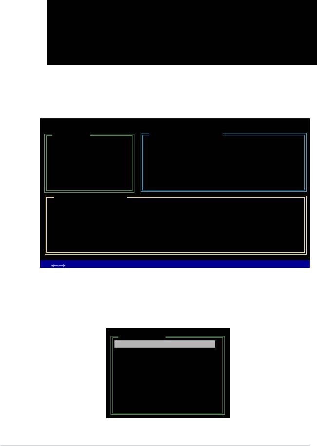
Entering the JMB363 RAID BIOS utility
1. During POST, press <Ctrl-J> to enter the JBM363 RAID BIOS menu.
JMicron Technology Corp. PCI-to-SATA II/IDE RAID Controller BIOS v0.97
Copyright (C) 2004-2005 JMicron Technology http://www. jmicron.com
HDD0 : HDS722516VLSA80 164 GB Non-RAID
HDD1 : HDS722516DLA380 164 GB Non-RAID
Press <Ctrl-J> to enter RAID Setup Utility...
2. The main JMB363 RAID BIOS menu appears.
3. Use the arrow keys to move the color bar and navigate through the items.
JMicron Technology Corp. PCI-to-SATA II/IDE RAID Controller BIOS v0.97
[Main Menu]
[Hard Disk Drive List]
Create RAID Disk Drive
Model Name Capacity Type/Status
Delete RAID Disk Drive
HDD0: HDS722516VLSA80 164 GB Non-RAID
Revert HDD to Non-RAID
HDD1: HDS722516DLA380 164 GB Non-RAID
Solve Mirror Conict
Rebuild Mirror Drive
Save and Exit Setup
Exit Without Saving
[RAID Disk Drive List]
[
TAB]-Switch Window [
↑↓
]-Select Item [ENTER]-Action [ESC]-Exit
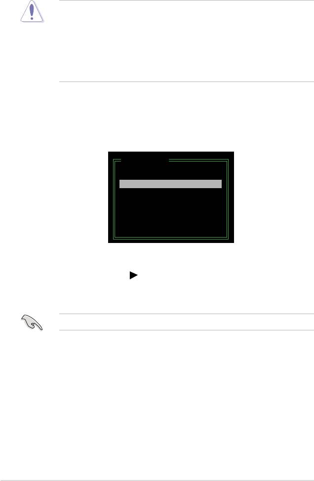
Creating a RAID set
1. In the main JMB363 RAID BIOS menu, highlight Create RAID Disk Drive
using the up/down arrow key then press <Enter>.
[Main Menu]
Create RAID Disk Drive
Delete RAID Disk Drive
Revert HDD to Non-RAID
Solve Mirror Conict
Rebuild Mirror Drive
Save and Exit Setup
Exit Without Saving
5-30 Chapter 5: Software support
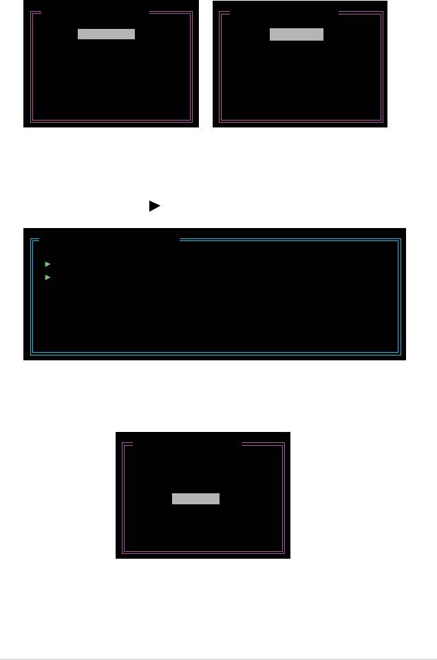
2. When the Level item is highlighted, use the up/down arrow key to select the
RAID set that you want to create.
[Create New RAID]
[Create New RAID]
Name : JRAID
Name : JRAID
Level: 0-Stripe
Level: 1-Mirror
Disks: Select Disk
Disks: Select Disk
Block: 128 KB
Block: N/A
Size : 319 GB
Size : 159 GB
Conrm Creation
Conrm Creation
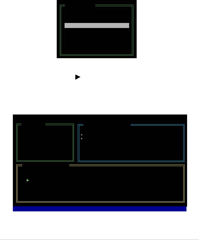
3. When the Disks item is highlighted, use the up/down arrow key to highlight
an HDD that you want to belong to the RAID set, then press the space bar to
conrm selection. Repeat the process until the HDDs are selected.
A selected HDD shows a
sign before it.
[Hard Disk Drive List]
Model Name Capacity Type/Status
HDD0: HDS722516VLSA80 XXX GB Non-RAID
HDD1: HDS722516DLA380 XXX GB Non-RAID
4. Key in the RAID volume capacity. Use the up/down arrow to choose the block
size. The default value indicates the maximum allowed capacity.
[Create New RAID]
Name : JRAID
Level: 0-Stripe
Disks: Select Disk
Block: 128 KB
Size : 319 GB
Conrm Creation
ASUS P5K 5-31
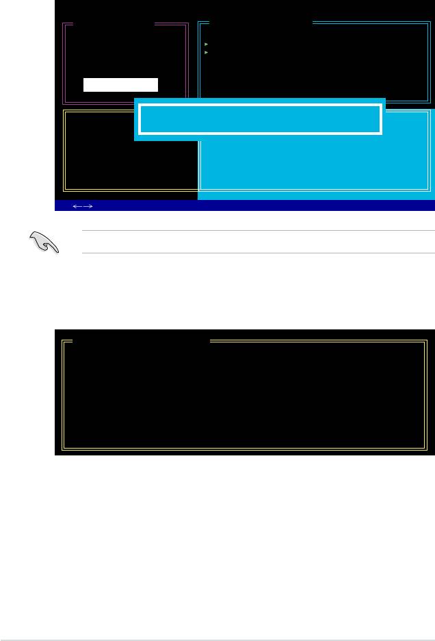
5. When done, press <Enter> to conrm the creation of the RAID set. A dialogue
box appears to conrm the action. Press <Y> to conrm; otherwise, press
<N>.
JMicron Technology Corp. PCI-to-SATA II/IDE RAID Controller BIOS v0.97
[Create New RAID]
[Hard Disk Drive List]
Name: JRAID
Model Name Available Type/Status
Level: 0-Stripe
HDD0: HDS722516VLSA80 164 GB Non-RAID
Disks: Select Disk
HDD1: HDS722516DLA380 164 GB Non-RAID
Block: 128 KB
Size : 319 GB
Conrm Creation
[RAID Disk Drive List]
Create RAID on the selected HDD (Y/N)? Y
CONFIRM RAID CREATION
ALL DATA ON THE SELECTED HARD DISK
WILL BE LOST WHEN EXIT WITH SAVING
[
TAB]-Switch Window [
↑↓
]-Select Item [ENTER]-Action [ESC]-Exit
Pressing <Y> deletes all the data in the HDDs.
6. The following screen appears, displaying the relevant information about the
RAID set you created.
[RAID Disk Drive List]
Model Name RAID Level Capacity Status Members(HDDx)
RDD0: JRAID 0-Stripe XXX GB Normal 01
5-32 Chapter 5: Software support
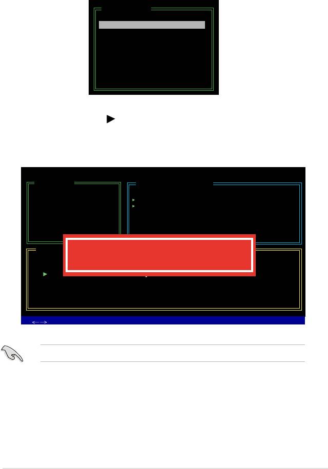
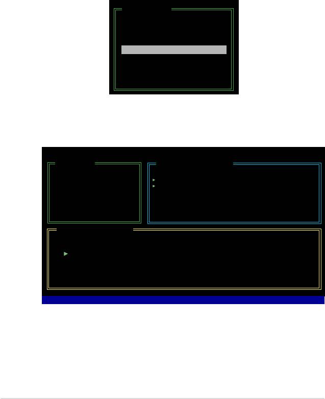
Deleting a RAID set
1. In the main JMB363 RAID BIOS menu, highlight Delete RAID Disk Drive
using the up/down arrow key then press <Enter>.
[Main Menu]
Create RAID Disk Drive
Delete RAID Disk Drive
Revert HDD to Non-RAID
Solve Mirror Conict
Rebuild Mirror Drive
Save and Exit Setup
Exit Without Saving
2. Use the space bar to select the RAID set you want to delete.
A selected set shows a
sign before it. Press the <Del> key to delete the
set.
3. A dialogue box appears to conrm the action. Press <Y> to conrm;
otherwise, press <N>.
JMicron Technology Corp. PCI-to-SATA II/IDE RAID Controller BIOS v0.97
[Main Menu]
[Hard Disk Drive List]
Create RAID Disk Drive
Model Name Capacity Type/Status
Delete RAID Disk Drive
HDD0: HDS722516VLSA80 164 GB RAID Inside
Revert HDD to Non-RAID
HDD1: HDS722516DLA380 164 GB RAID Inside
Solve Mirror Conict
Rebuild Mirror Drive
Save and Exit Setup
Exit Without Saving
[RAID Disk Drive List]
ALL DATA ON THE RAID WILL BE LOST!!
Model Name RAID Level Capacity Status
ARE YOU SURE TO DELETE (Y/N)? Y
Members(HDDx)
RDD0: JRAID 0-Stripe XXX GB Normal 01
[
TAB]-Switch Window [
↑↓
]-Select Item [ENTER]-Action [ESC]-Exit
Pressing <Y> deletes all the data in the HDDs.
ASUS P5K 5-33
Resetting disks to non-RAID
An HDD that has been previously congured as part of another RAID set in
another platform is called a broken RAID HDD. When you install a broken RAID
HDD, you cannot select this HDD when conguring a RAID set through the
JMB363 utility.
If you still want to use this broken RAID HDD as part of the RAID set congured
through the JMB363, you may do so by resetting the disk to non-RAID. You will,
however, lose all data and previous RAID congurations.
To reset disks to non-RAID:
1. In the main JMB363 RAID BIOS menu, highlight Revert HDD to non-RAID
using the up/down arrow key then press <Enter>.
[Main Menu]
Create RAID Disk Drive
Delete RAID Disk Drive
Revert HDD to Non-RAID
Solve Mirror Conict
Rebuild Mirror Drive
Save and Exit Setup
Exit Without Saving
2. Use the space bar to select the HDD that you want to reset to non-RAID.
A selected HDD shows a
sign before it.
3. A dialogue box appears to conrm the action. Press <Y> to conrm;
otherwise, press <N>.
Pressing <Y> deletes all the data in the HDD.
5-34 Chapter 5: Software support
Solving a Mirror conict
A Mirror conict occurs when both disks in a RAID 1 (Mirror) conguration are
unplugged from the system in turn, then plugged in again. Since both disks contain
exactly the same data, the system will be unable to determine which of the two
is the source drive. This option allows you to set the source drive and rebuild the
Mirror drive according to the contents of the source drive.
To solve a Mirror conict:
1. In the main JMB363 RAID BIOS menu, highlight Solve Mirror Conict using
the up/down arrow key then press <Enter>.
[Main Menu]
Create RAID Disk Drive
Delete RAID Disk Drive
Revert HDD to Non-RAID
Solve Mirror Conict
Rebuild Mirror Drive
Save and Exit Setup
Exit Without Saving
2. Use the space bar to select the HDD that you want to set as source drive.
The selected HDD shows a
sign before it.
3. Using the <TAB>, move to the RAID Disk Drive List menu and highlight the
RAID set that you want to rebuild. Press <Del> to begin rebuilding the Mirror
conguration.
A status bar at the bottom of the screen shows the progress of the rebuilding.
JMicron Technology Corp. PCI-to-SATA II/IDE RAID Controller BIOS v0.97
[Main Menu]
[Hard Disk Drive List]
Create RAID Disk Drive
Model Name Capacity Type/Status
Delete RAID Disk Drive
HDD0: HDS722516VLSA80 164 GB RAID Inside
Revert HDD to Non-RAID
HDD1: HDS722516DLA380 164 GB RAID Inside
Solve Mirror Conict
Rebuild Mirror Drive
Save and Exit Setup
Exit Without Saving
[RAID Disk Drive List]
Model Name RAID Level Capacity Status
Members(HDDx)
RDD0: JRAID 1-Mirror XXX GB Rebuild 01
Rebuilding... 01%, please wait...
ASUS P5K 5-35
Rebuilding a Mirror Drive
When one of the disks in a RAID 1 (Mirror) conguration is unplugged from the
system, then plugged in again, a dialogue box appears to ask you to rebuild the
Mirror drive. Press <Y> to conrm; otherwise, press <N>.
This option allows you to rebuild the Mirror drive later and synchronize the data
between two hard disks.
To rebuild a Mirror drive:
1. In the main JMB363 RAID BIOS menu, highlight Rebuild Mirror Drive using
the up/down arrow key then press <Enter>.
[Main Menu]
Create RAID Disk Drive
Delete RAID Disk Drive
Revert HDD to Non-RAID
Solve Mirror Conict
Rebuild Mirror Drive
Save and Exit Setup
Exit Without Saving
2. Using the <TAB>, move to the RAID Disk Drive List menu and highlight the
RAID set that you want to rebuild. Press <Del> to begin rebuilding the Mirror
conguration.
A status bar at the bottom of the screen shows the progress of the rebuilding.
JMicron Technology Corp. PCI-to-SATA II/IDE RAID Controller BIOS v0.97
[Main Menu]
[Hard Disk Drive List]
Create RAID Disk Drive
Model Name Capacity Type/Status
Delete RAID Disk Drive
HDD0: HDS722516VLSA80 164 GB RAID Inside
Revert HDD to Non-RAID
HDD1: HDS722516DLA380 164 GB RAID Inside
Solve Mirror Conict
Rebuild Mirror Drive
Save and Exit Setup
Exit Without Saving
[RAID Disk Drive List]
Model Name RAID Level Capacity Status
Members(HDDx)
RDD0: JRAID 1-Mirror XXX GB Rebuild 01
Rebuilding... 01%, please wait...
Saving the settings and exiting setup
When you have nished, highlight Save & Exit Setup using the up/down arrow key
then press <Enter> to save the current RAID conguration and exit the JMB363
RAID BOS utility.
A dialogue box appears to conrm the action. Press <Y> to conrm; otherwise,
press <N> to return to the JMB RAID BIOS menu.
5-36 Chapter 5: Software support

5.5 Creating a RAID driver disk
®
A oppy disk with the RAID driver is required when installing Windows
XP
operating system on a hard disk drive that is included in a RAID set. For
®
Windows
Vista operating system, use either a oppy disk or a USB device with
the RAID driver.
5.5.1 Creating a RAID driver disk without entering the OS
To create a RAID/SATA driver disk without entering the OS:
1. Boot your computer.
2. Press <Del> during POST to enter the BIOS setup utility.
3. Set the optical drive as the primary boot device.
4. Insert the support CD into the optical drive.
5. Save changes and exit BIOS.
6. Press any key when the system prompts “Press any key to boot from the
optical drive.”
7. When the menu appears, press <1> to create a RAID driver disk.
8. Insert a formatted oppy disk into the oppy drive then press <Enter>.
9. Follow succeeding screen instructions to complete the process.
®
5.5.2 Creating a RAID/SATA driver disk in Windows
®
To create a RAID driver disk in Windows
:
®
1. Start Windows
.
2. Place the motherboard support CD into the optical drive.
3. Go to the Make Disk menu, then click
JMicron JMB36X 32/64bit RAID
®
Driver
to create a JMicron
JMB363 RAID driver disk.
4. Insert a oppy disk/USB device into the oppy disk drive/USB port.
5. Follow succeeding screen instructions to complete the process.
Write-protect the oppy disk to avoid computer virus infection.
®
To install the RAID driver in Windows
XP:
1. During the OS installation, the system prompts you to press the F6 key to
install third-party SCSI or RAID driver.
2. Press <F6> then insert the oppy disk with RAID driver into the oppy disk
drive.
3. When prompted to select the SCSI adapter to install, make sure you select
JMicron JMB363
.
4. Follow the succeeding screen instructions to complete the installation.
ASUS P5K 5-37

®
To install the RAID driver in Windows
Vista:
1. Insert the oppy disk/USB device with RAID driver into the oppy disk drive/USB
port.
2. During the OS installation, select
JMicron JMB363.
3. Follow the succeeding screen instructions to complete the installation.
5-38 Chapter 5: Software support
