Asus P5K: Hardware
Hardware: Asus P5K
This chapter lists the hardware setup
procedures that you have to perform
when installing system components. It
includes description of the jumpers and
connectors on the motherboard.
Hardware
2
information

Chapter summary
2
2.1 Before you proceed ..................................................................... 2-1
2.2 Motherboard overview .................................................................
2-2
2.3 Central Processing Unit (CPU) ...................................................
2-6
2.4 System memory .........................................................................
2-13
2.5 Expansion slots ..........................................................................
2-19
2.6 Jumper ........................................................................................
2-24
2.7 Connectors .................................................................................
2-25
ASUS P5K
2.1 Before you proceed
Take note of the following precautions before you install motherboard components
or change any motherboard settings.
• Unplug the power cord from the wall socket before touching any
component.
• Use a grounded wrist strap or touch a safely grounded object or a metal
object, such as the power supply case, before handling components to
avoid damaging them due to static electricity.
• Hold components by the edges to avoid touching the ICs on them.
• Whenever you uninstall any component, place it on a grounded antistatic
pad or in the bag that came with the component.
• Before you install or remove any component, ensure that the ATX power
supply is switched off or the power cord is detached from the power
supply. Failure to do so may cause severe damage to the motherboard,
peripherals, and/or components.
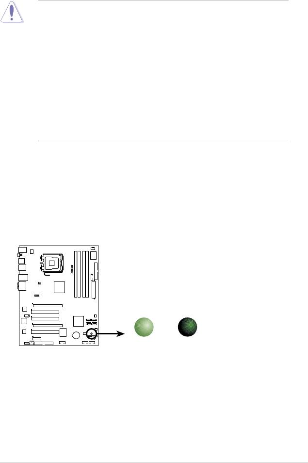
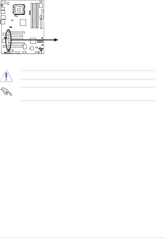
Onboard LED
The motherboard comes with a standby power LED that lights up to indicate that
the system is ON, in sleep mode, or in soft-off mode. This is a reminder that you
should shut down the system and unplug the power cable before removing or
plugging in any motherboard component. The illustration below shows the location
of the onboard LED.
ASUS P5K 2-1
®
P5K
SB_PWR
ON
OFF
Standby
Powered
P5K Onboard LED
Power
Off
2-2 Chapter 2: Hardware information
®
P5K
2.2 Motherboard overview
Before you install the motherboard, study the conguration of your chassis to
ensure that the motherboard ts into it.
Make sure to unplug the power cord before installing or removing the
motherboard. Failure to do so can cause you physical injury and damage
motherboard components.
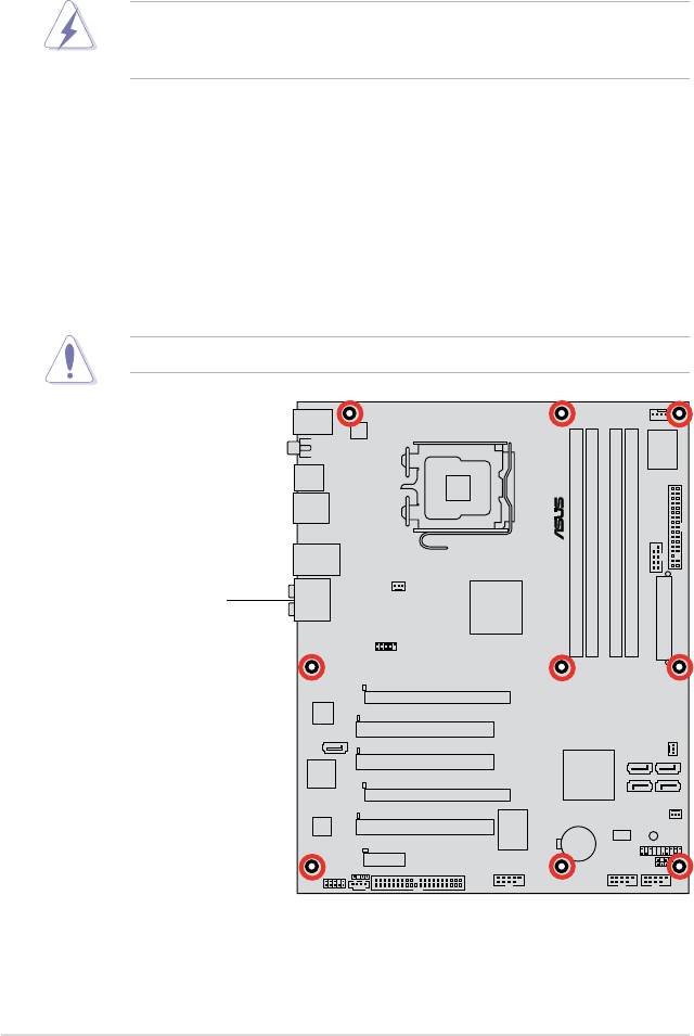
2.2.1 Placement direction
When installing the motherboard, make sure that you place it into the chassis in
the correct orientation. The edge with external ports goes to the rear part of the
chassis as indicated in the image below.
2.2.2 Screw holes
Place nine (9) screws into the holes indicated by circles to secure the motherboard
to the chassis.
Do not overtighten the screws! Doing so can damage the motherboard.
Place this side towards
the rear of the chassis
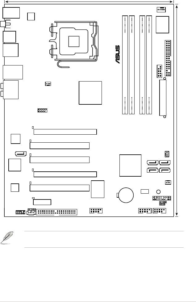
2.2.3 Motherboard layout
ASUS P5K 2-3
24.5cm (9.6in)
KB_USB56
CPU_FAN
ATX12V
SPDIF_O1
I/O
Super
LGA775
USB34
®
FLOPPY
F_ESATA
COM1
LAN1_USB12
CHA_FAN1
AUDIO
®
Intel
P35
DDR2 DIMM_A1 (64 bit,240-pin module)
DDR2 DIMM_A2 (64 bit,240-pin module)
DDR2 DIMM_B1 (64 bit,240-pin module)
DDR2 DIMM_B2 (64 bit,240-pin module)
EATXPWR
USB1112
P5K
30.5cm (12.0in)
DET_X16_1
PCIEX16_1
LAN
DET_PCI1
PCI1
SATA_E2
PWR_FAN
DET_PCI2
SATA2
SATA1
PCI2
®
Intel
JMB363
ICH9
DET_X16_2
PCIEX16_2
SATA4
SATA3
DET_PCI3
CHA_FAN2
ALC883
PCI3
SB_PWR
VIA
BIOS
CR2032 3V
Lithium Cell
PANEL
VT6308P
DET_EX1_1
CMOS Power
PCIEX1_1
CHASSIS
CLRTC
SPDIF_OUT
PRI_EIDE
AAFP
CD
IE1394_2 USB78
USB910
Refer to 2.7 Connectors for more information about rear panel connectors and
internal connectors.
2.2.4 Layout contents
Slots Page
1. DDR2 DIMM slots 2-13
2. PCI slots
2-21
3 PCI Express x1 slot
2-21
4. PCI Express x16 slots
2-21
Jumper Page
1. Clear RTC RAM (3-pin CLRTC) 2-24
Rear panel connectors Page
1. PS/2 keyboard port (purple) 2-25
2. IEEE 1394a port
2-25
3. LAN (RJ-45) port
2-25
4. Center/Subwoofer port (orange)
2-25
5. Rear Speaker Out port (black)
2-25
6. Line In port (light blue)
2-25
7. Line Out port (lime)
2-25
10. Microphone port (pink)
2-25
11. Side Speaker Out port (gray)
2-25
12. USB 2.0 ports 1 and 2
2-26
13. External SATA port
2-26
14. USB 2.0 ports 3 and 4
2-27
15. Coaxial S/PDIF Out port
2-27
16. USB 2.0 ports 5 and 6
2-27
2-4 Chapter 2: Hardware information

Internal connectors Page
1. Floppy disk drive connector (34-1 pin FLOPPY) 2-28
2. IDE connector (40-1 pin PRI_EIDE
) 2-29
3. ICh9 Serial ATA connectors (7-pin SATA1 [red], SATA2 [red],
2-30
SATA3 [black], SATA4 [black])
®
4. JMicron JMB363
Serial ATA RAID connector (7-pin SATA_E2) 2-31
5. Digital audio connector (4-1 pin SPDIF_OUT) 2-31
6. USB connectors (10-1 pin USB78, USB910, USB1112
) 2-32
7. IEEE 1394a port connector (10-1 pin IE1394_2) 2-32
8. Optical drive audio connector (4-pin CD) 2-33
9. CPU, chassis, and power fan connectors
2-34
(4-pin CPU_FAN, 3-pin CHA_FAN1, 3-pin CHA_FAN2,
3-pin PWR_FAN)
10. Serial port connector (10-1 pin COM1)
2-34
11. Chassis intrusion connector (4-1 pin CHASSIS) 2-35
12. Front panel connector (10-1 pin AAFP)
2-35
13. ATX power connectors (24-pin EATXPWR, 4-pin EATX12V) 2-36
14. System panel connector (20-8-pin PANEL
)
2-37
• System power LED (2-pin PLED)
• Hard disk drive activity LED (2-pin IDE_LED)
• System warning speaker (4-pin SPEAKER)
• ATX power button/soft-off button (2-pin PWR)
• Reset button (2-pin RESET)
15. ASUS Q-connector (system panel) 2-38
ASUS P5K 2-5
2.3 Central Processing Unit (CPU)
The motherboard comes with a surface mount LGA775 socket designed for the
®
™
®
™
™
®
Intel
Core
2 Quad / Intel
Core
2 Extreme / Core
2 Duo / Pentium
Extreme /
®
®
®
Pentium
D/ Pentium
4 / Celeron
D processors.
• Make sure that all power cables are unplugged before installing the CPU.
• Connect the chassis fan cable to the CHA_FAN1 connector to ensure
system stability.
•
Upon purchase of the motherboard, make sure that the PnP cap is on
the socket and the socket contacts are not bent. Contact your retailer
immediately if the PnP cap is missing, or if you see any damage to the PnP
cap/socket contacts/motherboard components. ASUS will shoulder the cost
of repair only if the damage is shipment/transit-related.
•
Keep the cap after installing the motherboard. ASUS will process Return
Merchandise Authorization (RMA) requests only if the motherboard comes
with the cap on the LGA775 socket.
• The product warranty does not cover damage to the socket contacts
resulting from incorrect CPU installation/removal, or misplacement/loss/
incorrect removal of the PnP cap.
2-6 Chapter 2: Hardware information
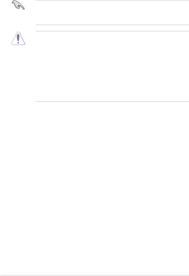
2.3.1 Installing the CPU
To install a CPU:
1. Locate the CPU socket on the motherboard.
Before installing the CPU, make sure that the socket box is facing towards you
and the load lever is on your left.
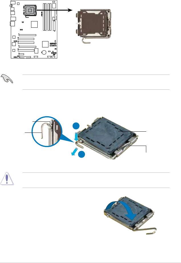
2. Press the load lever with your thumb (A), then move it to the left (B) until it is
released from the retention tab.
Retention tab
A
PnP cap
Load lever
B
This side of the socket box
should face you.
To prevent damage to the socket pins, do not remove the PnP cap unless you
are installing a CPU.
3. Lift the load lever in the direction of
the arrow to a 135º angle.
ASUS P5K 2-7
®
P5K
P5K CPU Socket 775
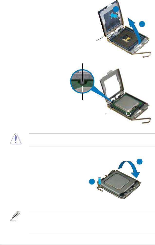
4. Lift the load plate with your thumb
and forenger to a 100º angle (A),
B
then push the PnP cap from the load
plate window to remove (B).
A
Load plate
Alignment key
5. Position the CPU over the
socket, making sure that
the gold triangle is on the
bottom-left corner of the
socket then t the socket
alignment key into the
CPU notch
CPU notch.
Gold triangle mark
The CPU ts in only one correct orientation. DO NOT force the CPU into the
socket to prevent bending the connectors on the socket and damaging the CPU!
A
6. Close the load plate (A), then
push the load lever (B) until it
snaps into the retention tab.
7. If installing a dual-core CPU,
B
connect the chassis fan cable
to the CHA_FAN1 connector to
ensure system stability.
®
®
The motherboard supports Intel
LGA775 processors with the Intel
Enhanced
®
Memory 64 Technology (EM64T), Enhanced Intel SpeedStep
Technology
(EIST), and Hyper-Threading Technology. Refer to the Appendix for more
information on these CPU features.
2-8 Chapter 2: Hardware information
2.3.2 Installing the CPU heatsink and fan
®
The Intel
LGA775 processor requires a specially designed heatsink and fan
assembly to ensure optimum thermal condition and performance.
®
•
When you buy a boxed Intel
processor, the package includes the CPU fan
and heatsink assembly. If you buy a CPU separately, make sure that you
®
use only Intel
-certied multi-directional heatsink and fan.
®
• Your Intel
LGA775 heatsink and fan assembly comes in a push-pin design
and requires no tool to install.
• If you purchased a separate CPU heatsink and fan assembly, make sure
that you have properly applied Thermal Interface Material to the CPU
heatsink or CPU before you install the heatsink and fan assembly.
Make sure that you have installed the motherboard to the chassis before you
install the CPU fan and heatsink assembly.
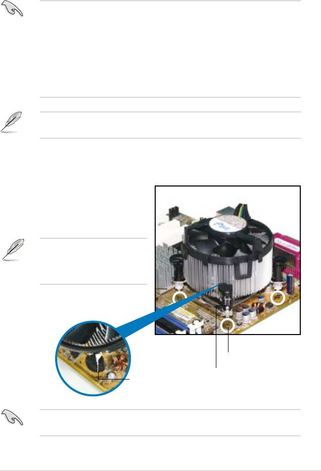
To install the CPU heatsink and fan:
1. Place the heatsink on top of the
installed CPU, making sure that
the four fasteners match the holes
on the motherboard.
Orient the heatsink and fan
assembly such that the CPU fan
cable is closest to the CPU fan
connector.
Motherboard hole
Fastener
Narrow end
of the groove
Make sure to orient each fastener with the narrow end of the groove pointing
outward. (The photo shows the groove shaded for emphasis.)
ASUS P5K 2-9
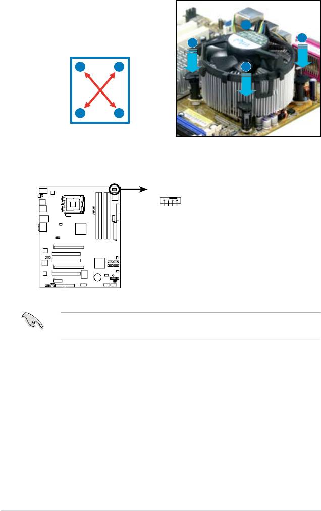
2. Push down two fasteners at a time in
a diagonal sequence to secure the
B
heatsink and fan assembly in place.
A
A
A
B
B
B
A
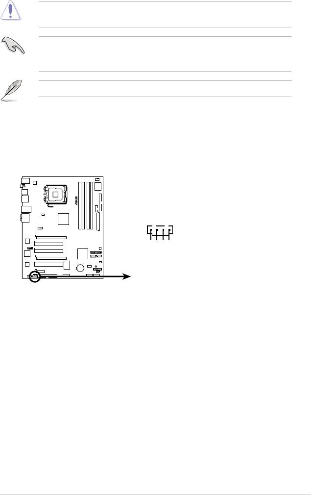
3. Connect the CPU fan cable to the connector on the motherboard labeled
CPU_FAN.
Do not forget to connect the CPU fan connector! Hardware monitoring errors
can occur if you fail to plug this connector.
2-10 Chapter 2: Hardware information
CPU_FAN
®
CPU FAN PWM
CPU FAN IN
CPU FAN PWR
GND
P5K
P5K CPU fan connector
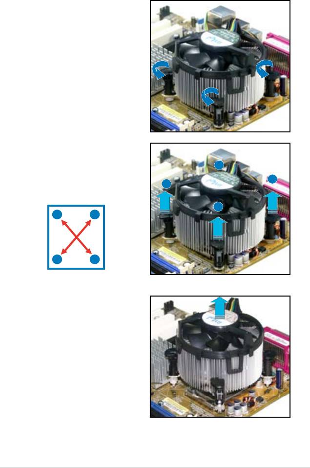
2.3.3 Uninstalling the CPU heatsink and fan
To uninstall the CPU heatsink and fan:
1. Disconnect the CPU fan cable from
the connector on the motherboard.
2. Rotate each fastener
counterclockwise.
3. Pull up two fasteners at a time in
a diagonal sequence to disengage
B
the heatsink and fan assembly
from the motherboard.
A
A
B
A
B
B
A
4. Carefully remove the heatsink
and fan assembly from the
motherboard.
ASUS P5K 2-11
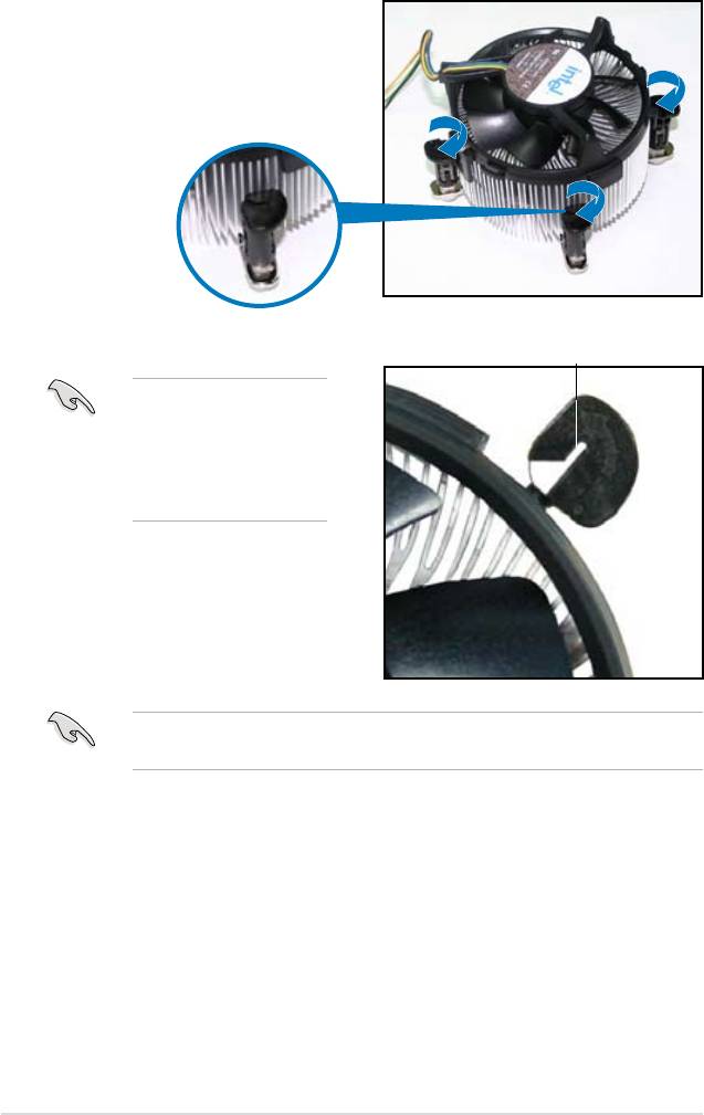
5. Rotate each fastener clockwise to
ensure correct orientation when
reinstalling.
Narrow end of the groove
The narrow end of the
groove should point
outward after resetting.
(The photo shows the
groove shaded for
emphasis.)
Refer to the documentation in the boxed or stand-alone CPU fan package for
detailed information on CPU fan installation.
2-12 Chapter 2: Hardware information
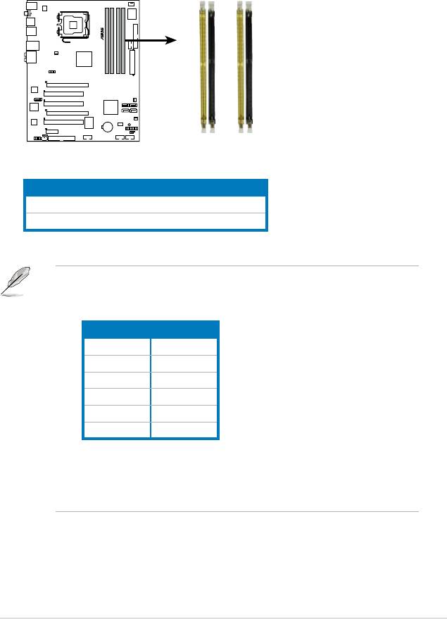
2.4 System memory
2.4.1 Overview
The motherboard comes with four Double Data Rate 2 (DDR2) Dual Inline Memory
Modules (DIMM) sockets.
The gure illustrates the location of the DDR2 DIMM sockets:
Channel Sockets
Channel A DIMM_A1 and DIMM_A2
Channel B DIMM_B1 and DIMM_B2
ASUS P5K 2-13
®
P5K
DIMM_A1
DIMM_A2
DIMM_B1
DIMM_B2
P5K 240-pin DDR2 DIMM sockets
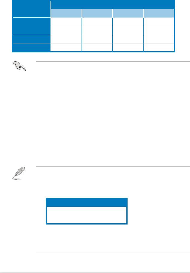
• This chipset ofcially supports DDR2-800 MHz. With the ASUS Super
Memspeed Technology, this motherboard natively supports up to
DDR2-1066 MHz. See the table below.
FSB DDR2
1333 1066*
1333 800
1333 667
1066 1066*
1066 800
1066 667
• *If you install a DDR2-1066 memory module whose SPD is DDR2-800,
make sure that you set the DRAM Frequency item in BIOS to
[DDR2-1066MHz]. See section 4.4.1 Jumperfree Conguration for
details.
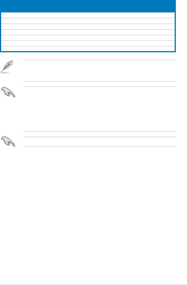
2.4.2 Memory congurations
You may install 256 MB, 512 MB, 1 GB, and 2 GB unbuffered non-ECC DDR2
DIMMs into the DIMM sockets.
Recommended Memory Congurations
Sockets
Mode
DIMM_A1 DIMM_B1 DIMM_A2 DIMM_B2
- Populated - -
Single-Channel
Populated - - -
Dual-channel (1) Populated Populated - -
Dual-channel (2) Populated Populated Populated Populated
• You may install varying memory sizes in Channel A and Channel B. The
system maps the total size of the lower-sized channel for the dual-channel
conguration. Any excess memory from the higher-sized channel is then
mapped for single-channel operation.
• Always install DIMMs with the same CAS latency. For optimum compatibility,
it is recommended that you obtain memory modules from the same vendor.
• If you install four 1 GB memory modules, the system may only recognize less
than 3GB because the address space is reserved for other critical functions.
®
This limitation appears on Windows
XP/Vista 32-bit operation system which
does not support Physical Address Extension (PAE).
®
• If you install Windows
XP/Vista 32-bit operation system, a total memory of
less than 3GB is recommended.
• This motherboard does not support memory modules made up of 128 Mb
chips.
Notes on memory limitations
• Due to chipset limitation, this motherboard can only support up to
8 GB on the operating systems listed below. You may install a maximum of
2 GB DIMMs on each slot.
64-bit
®
Windows
XP Professional x64 Edition
®
Windows
Vista x64 Edition
®
• Some old-version DDR2-800/667 DIMMs may not match Intel
’s
On-Die-Termination (ODT) requirement and will automatically downgrade
to run at DDR2-533. If this happens, contact your memory vendor to check
the ODT value.
2-14 Chapter 2: Hardware information
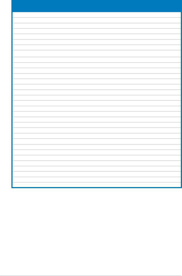
P5K Motherboard Qualied Vendors Lists (QVL)
DDR2-1066 MHz capability
SS/
DIMM support
Size Vendor
Part No.
DS
A* B* C*
1024MB CORSAIR DS XMS8505v1.1 / 0616126-12 • •
1024MB CORSAIR DS CM2X1024-8500 • • •
1024MB CORSAIR DS CM2X1024-9136C5D • •
512MB Kingston SS KHX9200D2 / 512 9905315-054.A00LF / 2.3-2.35v • • •
1024MB Kingston DS KHX9200D2 / 1G / 9905315-064.A00LF / 2.3-2.35v • • •
1024MB OCZ DS OCZ2FX11502GK / PC2 9200 /1G Dual CH /FlexXLC • • •
1024MB Kingston DS KHX9600D2 / 1G / 9905316-069.A00LF / 2.3-2.35v • •
If you install a DDR2-1066 memory module whose SPD is DDR2-800, make
sure that you set the DRAM Frequency item in BIOS to [DDR2-1066MHz]. See
section 4.4.1 Jumperfree Conguration for details.
• A*: Supports one module inserted in any slot as Single-channel memory
conguration.
• B*: Supports one pair of modules inserted into either the yellow slots or the
black slots as one pair of Dual-channel memory conguration.
• C*: Supports 4 modules inserted into both the yellow and black slots as two
pairs of Dual-channel memory conguration.
Visit the ASUS website for the latest DDR2-1066/800/667MHz QVL.
ASUS P5K 2-15
P5K Motherboard Qualied Vendors Lists (QVL)
DDR2-800 MHz capability
SS/
DIMM support
Size Vendor Chip No.
Part No.
DS
A* B* C*
512MB KINGSTON K4T51083QC SS KVR800D2N5/512 • • •
1024MB KINGSTON Heat-Sink Package SS KHX6400D2LLK2/1GN • • •
1024MB KINGSTON V59C1512804QBF25 DS KVR800D2N5/1G • • •
256MB Qimonda HYB18T512160BF-25F SS HYS64T32000HU-25F-B • • •
512MB Qimonda HYB18T512800BF25F SS HYS64T64000HU-25F-B • • •
1024MB Qimonda HYB18T512800BF25F DS HYS64T128020HU-25F-B • • •
512MB SAMSUNG EDD339XX SS M378T6553CZ3-CE7 • • •
256MB SAMSUNG K4T51163QC-ZCE7 SS M378T3354CZ3-CE7 • • •
512MB SAMSUNG ZCE7K4T51083QC SS M378T6553CZ3-CE7 • • •
512MB Hynix HY5PS12821CFP-S5 SS HYMP564U64CP8-S5 • • •
1024MB Hynix HY5PS12821CFP-S5 DS HYMP512U64CP8-S5 • • •
512MB MICRON 5JAIIZ9DQQ SS MT8HTF6464AY-80EA3 • • •
1024MB MICRON 5JAIIZ9DQQ DS MT16HTF12864AY-80EA3 • • •
512MB MICRON 5ZD22D9GKX SS MT8HTF6464AY-80ED4 • • •
1024MB MICRON 5ZD22D9GKX DS MT16HTF12864AY-80ED4 • • •
512MB MICRON 6CD22D9GKX SS MT8HTF6464AY-80ED4 • • •
1024MB MICRON 6CD22D9GKX DS MT16HTF12864AY-80ED4 • • •
1024MB CORSAIR Heat-Sink Package DS CM2X1024-6400C4 • • •
512MB Crucial Heat-Sink Package SS BL6464AA804.8FD • • •
512MB Crucial Heat-Sink Package SS BL6464AA804.8FD3 • • •
1024MB Crucial Heat-Sink Package DS BL12864AA804.16FD • • •
1024MB Crucial Heat-Sink Package DS BL12864AL804.16FD3 • • •
1024MB Crucial Heat-Sink Package DS BL12864AA804.16FD3 • • •
512MB Apacer Heat-Sink Package DS AHU512E800C5K1C • •
512MB A-DATA AD29608A8A-25EG SS M2OAD6G3H3160G1E53 • • •
1024MB A-DATA AD26908A8A-25EG DS M2OAD6G3I4170I1E58 • •
512MB Super Talent Heat-Sink Package SS T800UA12C4 • • •
1024MB Super Talent Heat-Sink Package DS T800UB1GC4 • • •
512MB NANYA NT5TU64M8BE-25C SS NT512T64U880BY-25C • • •
1024MB NANYA NT5TU64M8BE-25C DS NT1GT64U8HB0BY-25C • • •
512MB PSC A3R12E3HEF641B9A05 SS AL6E8E63B8E1K • • •
1024MB PSC A3R12E3HEF641B9A05 DS AL7E8E63B-8E1K • • •
2-16 Chapter 2: Hardware information

P5K Motherboard Qualied Vendors Lists (QVL)
DDR2-667MHz capability
SS/
DIMM support
Size Vendor Chip No.
Part No.
DS
A* B* C*
512MB KINGSTON D6408TEBGGL3U SS KVR667D2N5/512 • • •
1024MB KINGSTON D6408TEBGGL3U DS KVR667D2N5/1G • • •
256MB KINGSTON HYB18T256800AF3S SS KVR667D2N5/256 • • •
256MB KINGSTON 6SBI2D9DCG SS KVR667D2N5/256 • • •
2048MB KINGSTON E1108AB-6E-E DS KVR667D2N5/2G • • •
256MB Qimonda HYB18T512160BF-3S SS HYS64T32000HU-3S-B • • •
512MB Qimonda HYB18T512800BF3S SS HYS64T64000HU-3S-B • • •
1024MB Qimonda HYB18T512800BF3S DS HYS64T128020HU-3S-B • • •
512MB SAMSUNG ZCE6K4T51083QC SS M378T6553CZ0-CE6 • • •
256MB SAMSUNG K4T51163QC-ZCE6 SS M378T3354CZ3-CE6 • • •
512MB SAMSUNG K4T51083QC SS M378T6553CZ3-CE6 • • •
1024MB SAMSUNG ZCE6K4T51083QC DS M378T2953CZ3-CE6 • • •
256MB SAMSUNG K4T51163QE-ZCE6 SS M378T3354EZ3-CE6 • • •
512MB SAMSUNG K4T51083QE DS M378T6553EZS-CE6 • • •
1024MB SAMSUNG K4T51083QE DS M378T2953EZ3-CE6 • • •
256MB Hynix HY5PS121621CFP-Y5 SS HYMP532U64CP6-Y5 • • •
1024MB Hynix HY5PS12821CFP-Y5 DS HYMP512U64CP8-Y5 • • •
256MB CORSAIR MIII00605 SS VS256MB667D2 • • •
512MB CORSAIR 64M8CFEG SS VS512MB667D2 • • •
1024MB CORSAIR 64M8CFEG DS VS1GB667D2 • • •
256MB ELPIDA E2508AB-6E-E SS EBE25UC8ABFA-6E-E • • •
512MB ELPIDA E5108AE-6E-E SS EBE51UD8AEFA-6E-E • • •
512MB A-DATA AD29608A8A-3EG SS M2OAD5G3H3166I1C52 • • •
1024MB A-DATA AD29608A8A-3EG DS M2OAD5G3I4176I1C52 • • •
2048MB A-DATA NT5TU128M8BJ-3C DS M2ONY5H3J4170I1C5Z • • •
512MB crucial Heat-Sink Package SS BL6464AA663.8FD • •
1024MB crucial Heat-Sink Package DS BL12864AL664.16FD • • •
512MB Apacer AM4B5708GQJS7E0628F SS AU512E667C5KBGC • • •
1024MB Apacer AM4B5708GQJS7E DS AU01GE667C5KBGC • • •
256MB Kingmax N2TU51216AG-3C SS KLCB68F-36KH5 • • •
512MB Kingmax KKEA88B4LAUG-29DX SS KLCC28F-A8KB5 • • •
1024MB Kingmax KKEA88B4LAUG-29DX DS KLCD48F-A8KB5 • • •
512MB Super Talent Heat-Sink Package SS T6UA512C5 • • •
1024MB Super Talent Heat-Sink Package DS T6UB1GC5 • • •
512MB SMART G64M8XB3ITIX4TUE SS TB3D2667C58S • • •
1024MB SMART G64M8XB3ITIX4TUE DS TB4D2667C58D • • •
2048MB NANYA NT5TU128M8BJ-3C DS NT2GT64U8HB0JY-3C • • •
512MB NANYA NT5TU64M8BE-3C SS NT512T64U88B0BY-3C • • •
512MB PSC A3R12E3GEF637BLC5N SS AL6E8E63B-6E1K • • •
1024MB PSC A3R12E3GEF637BLC5N DS AL7E8E63B-6E1K • • •
ASUS P5K 2-17
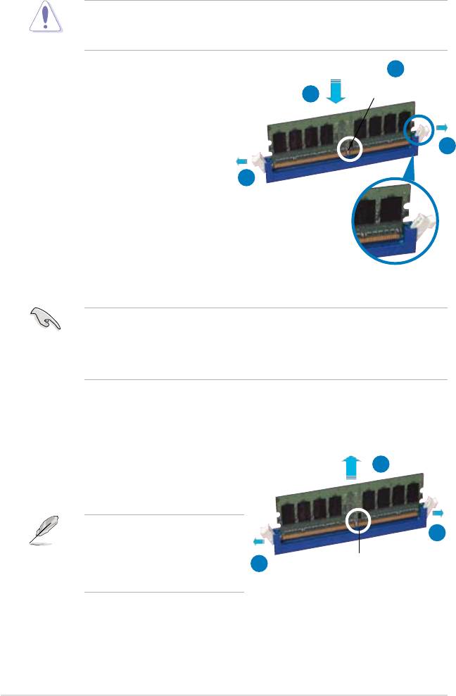
2.4.3 Installing a DIMM
Unplug the power supply before adding or removing DIMMs or other
system components. Failure to do so can cause severe damage to both the
motherboard and the components.
2
To install a DIMM:
DDR2 DIMM notch
3
1. Unlock a DIMM socket by
pressing the retaining clips
outward.
1
2. Align a DIMM on the socket
such that the notch on the DIMM
1
matches the break on the socket.
3. Firmly insert the DIMM into the
socket until the retaining clips
snap back in place and the DIMM
is properly seated.
Unlocked retaining clip
• A DDR2 DIMM is keyed with a notch so that it ts in only one direction. Do
not force a DIMM into a socket to avoid damaging the DIMM.
• The DDR2 DIMM sockets do not support DDR DIMMs. Do not install DDR
DIMMs to the DDR2 DIMM sockets.
2.4.4 Removing a DIMM
To remove a DIMM:
2
1. Simultaneously press the retaining
clips outward to unlock the DIMM.
Support the DIMM lightly with
1
your ngers when pressing the
retaining clips. The DIMM might
1
DDR2 DIMM notch
get damaged when it ips out with
extra force.
2. Remove the DIMM from the socket.
2-18 Chapter 2: Hardware information
2.5 Expansion slots
In the future, you may need to install expansion cards. The following sub-sections
describe the slots and the expansion cards that they support.
Make sure to unplug the power cord before adding or removing expansion
cards. Failure to do so may cause you physical injury and damage motherboard
components.
2.5.1 Installing an expansion card
To install an expansion card:
1. Before installing the expansion card, read the documentation that came with
it and make the necessary hardware settings for the card.
2. Remove the system unit cover (if your motherboard is already installed in a
chassis).
3. Remove the bracket opposite the slot that you intend to use. Keep the screw
for later use.
4. Align the card connector with the slot and press rmly until the card is
completely seated on the slot.
5. Secure the card to the chassis with the screw you removed earlier.
6. Replace the system cover.
2.5.2 Conguring an expansion card
After installing the expansion card, congure it by adjusting the software settings.
1. Turn on the system and change the necessary BIOS settings, if any. See
Chapter 4 for information on BIOS setup.
2. Assign an IRQ to the card. Refer to the tables on the next page.
3. Install the software drivers for the expansion card.
When using PCI cards on shared slots, ensure that the drivers support “Share
IRQ” or that the cards do not need IRQ assignments. Otherwise, conicts will
arise between the two PCI groups, making the system unstable and the card
inoperable. Refer to the table on the next page for details.
ASUS P5K 2-19
2.5.3 Interrupt assignments
IRQ Priority Standard function
0 1 System timer
1 2 Keyboard controller
2
– Re-direct to IRQ#9
3 11 IRQ holder for PCI steering*
4 12 Communications port (COM1)*
5 13 IRQ holder for PCI steering*
6 14 Floppy disk controller
7 15 Printer port (LPT1)*
8 3 System CMOS/Real Time Clock
9 4 IRQ holder for PCI steering*
10 5 IRQ holder for PCI steering*
11 6 IRQ holder for PCI steering*
12 7 PS/2 compatible mouse port*
13 8 Numeric data processor
14 9 Primary IDE channel
15 10 Secondary IDE channel
* These IRQs are usually available for PCI devices.
IRQ assignments for this motherboard
A B C D E F G H
PCI slot 1 shared – – – – – – –
PCI slot 2 – shared – – – – – –
PCI slot 3 – – shared – – – – –
LAN (L1) – shared – – – – – –
SATA (363) shared – – – – – – –
PCIE x16_1 shared – – – – – – –
PCIE x16_2 shared – – – – – – –
USB controller 1 – – – shared – – – –
USB controller 2 – – shared – – – – –
USB controller 3 shared – – – – – – –
USB controller 4 shared – – – – – – –
USB controller 5 – – – – – shared – –
USB 2.0 controller 1 – – – – – – – shared
USB 2.0 controller 2 – – shared – – – – –
SATA controller 1 – – shared – – – – –
SATA controller 2 – – – – – – shared –
Azalia – – – – – – shared –
2-20 Chapter 2: Hardware information
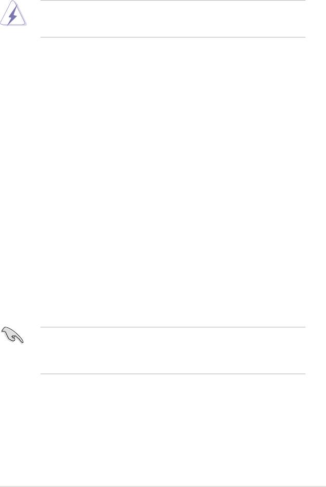
2.5.4 PCI slots
The PCI slots support cards such as
a LAN card, SCSI card, USB card,
and other cards that comply with PCI
specications. The gure shows a LAN
card installed on a PCI slot.
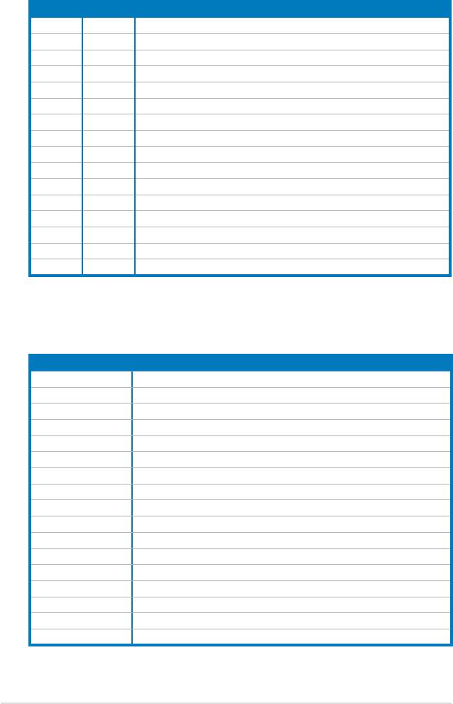
2.5.5 PCI Express x1 slot
This motherboard supports PCI Express
x1 network cards, SCSI cards and other
cards that comply with the PCI Express
specications. The following gure
shows a network card installed on the
PCI Express x1 slot.
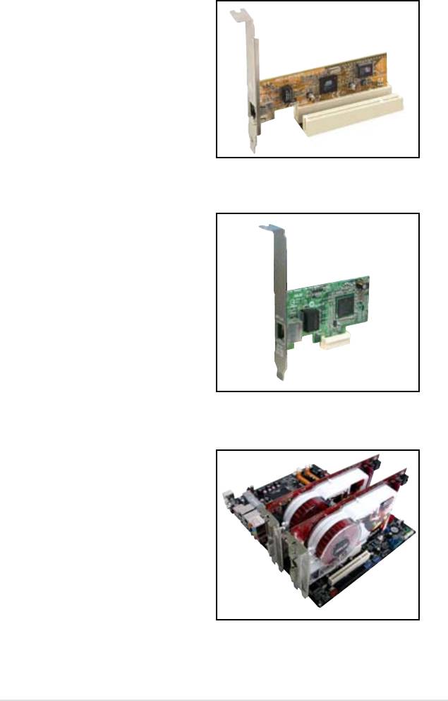
2.5.6 Two PCI Express x16 slots
This motherboard supports two ATI
CrossFire™ PCI Express x16 graphics
cards that comply with the PCI Express
specications.
The gure shows two graphics cards
installed on the PCI Express x16 slots.
ASUS P5K 2-21
We recommend that you install a VGA card on the primary (blue) PCI Express
slot, and install any other PCI Express device on the Universal PCI-E slot
(black).
Primary PCI Express x16 slot
The primary PCI Express x16 slot supports PCI Express x16 graphics cards that
comply with the PCI Express specications.
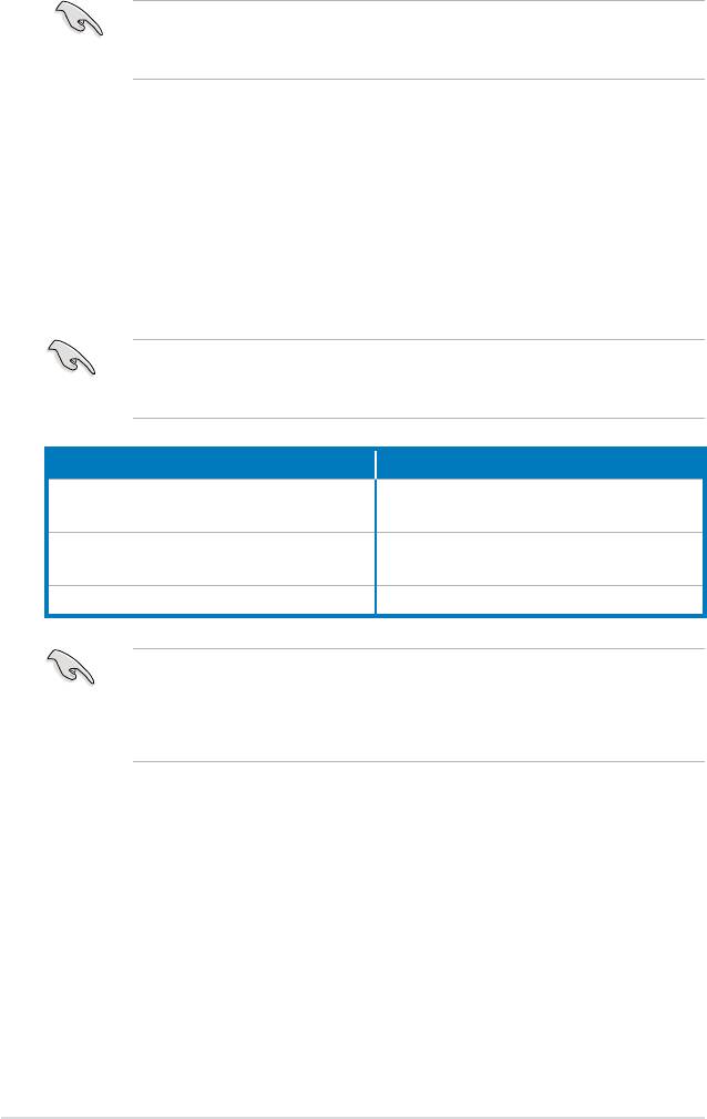
Universal PCI-E slot (max. x4 mode)
This motherboard also supports a Universal PCI-E slot with a maximum speed of 2
GB/s. The operating frequency of this slot changes, depending on the type of PCI
Express card you install. Refer to the table below for details.
If you install two VGA cards, we recommend that you plug the rear chassis
fan cable to the motherboard connector labeled CHA_FAN1 for better thermal
environment. See page 2-34 for the connector location.
Options for Universal PCI Express slot PCI Express operating speed
Auto Automatically optimizes performance and
functionality according to devices installed.
x4 mode [fast] User gets the best performance but this
mode disables the PCI Express x1 slot.
x2 mode [compatible] Always runs at PCI Express x2 speed.
•
Some PCI Express graphics cards cannot operate on x4/x2 mode. We suggest
that you install these cards on the primary PCI Express slot (blue) to increase
system stability.
•
Some PCI Express devices cannot operate on x4/x2 mode.
2-22 Chapter 2: Hardware information
2.5.7 AI Slot Detector
This motherboard comes with onboard LEDs that light up when the PCIE/PCI
devices are not correctly installed. This is a reminder that you should reinstall
these devices. Refer to the gure below for the location of the LEDs.
ASUS P5K 2-23
®
P5K
DET_X16_1
DET_PCI1
DET_PCI2
DET_X16_2
DET_PCI3
DET_PCIEX1_1
P5K Slot Detectors
When the LEDs light up, turn off the power before reinstalling the devices.
The PCIEX16_1 slot (blue) is for a PCIE x16 card. The DET_X16_1 LED lights
up despite correct installation when you install a x1, x4, or x8 card to this slot.
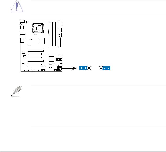
2.6 Jumper
1. Clear RTC RAM (3-pin CLRTC)
This jumper allows you to clear the Real Time Clock (RTC) RAM in
CMOS. You can clear the CMOS memory of date, time, and system setup
parameters by erasing the CMOS RTC RAM data. The onboard button
cell battery powers the RAM data in CMOS, which include system setup
information such as system passwords.
To erase the RTC RAM:
1. Turn OFF the computer and unplug the power cord.
2. Remove the onboard battery.
3. Move the jumper cap from pins 1-2 (default) to pins 2-3. Keep the cap on
pins 2-3 for about 5~10 seconds, then move the cap back to pins 1-2.
4. Reinstall the battery.
5. Plug the power cord and turn ON the computer.
6. Hold down the <Del> key during the boot process and enter BIOS setup
to re-enter data.
Except when clearing the RTC RAM, never remove the cap on CLRTC jumper
default position. Removing the cap will cause system boot failure!
• You do not need to clear the RTC when the system hangs due to
overclocking. For system failure due to overclocking, use the C.P.R. (CPU
Parameter Recall) feature. Shut down and reboot the system so the BIOS
can automatically reset parameter settings to default values.
• Due to the chipset limitation, AC power off is required prior using C.P.R.
function. You must turn off and on the power supply or unplug and plug the
power cord before reboot the system.
2-24 Chapter 2: Hardware information
®
P5K
CLRTC
1 2 2 3
Normal Clear RTC
P5K Clear RTC RAM
(Default)
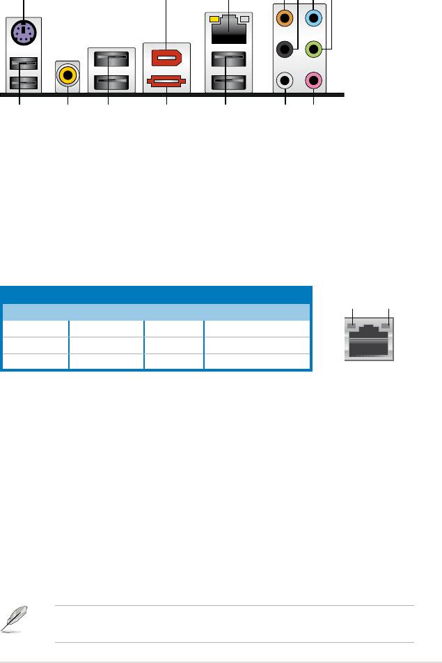
2.7 Connectors
2.7.1 Rear panel connectors
1. PS/2 keyboard port (purple). This port is for a PS/2 keyboard.
2. IEEE1394a port.
This 6-pin IEEE 1394a port provides high-speed
connectivity for audio/video devices, storage peripherals, PCs, or portable
devices.
3. LAN (RJ-45) port.
Supported by Gigabit LAN controller, this port allows
Gigabit connection to a Local Area Network (LAN) through a network hub.
Refer to the table below for the LAN port LED indications.
ASUS P5K 2-25
2
3
4
6 751
12
1113 89
1014
LAN port LED indications
ACT/LINK
SPEED
Activity/Link Speed LED
LED
LED
Status Description Status Description
OFF No link OFF 10 Mbps connection
ORANGE Linked ORANGE 100 Mbps connection
BLINKING Data activity GREEN 1 Gbps connection
LAN port
4. Center/Subwoofer port (orange).
This port connects the center/subwoofer
speakers.
5. Rear Speaker Out port (black).
This port connects the rear speakers in a
4-channel, 6-channel, or 8-channel audio conguration.
6. Line In port (light blue).
This port connects the tape, CD, DVD player, or
other audio sources.
7. Line Out port (lime).
This port connects a headphone or a speaker. In
4-channel, 6-channel, and 8-channel conguration, the function of this port
becomes Front Speaker Out.
8. Microphone port (pink).
This port connects a microphone.
9. Side Speaker Out port (gray).
This port connects the side speakers in an
8-channel audio conguration.
Refer to the audio conguration table on the next page for the function of the
audio ports in 2, 4, 6, or 8-channel conguration.
Audio 2, 4, 6, or 8-channel conguration
Headset
Port
4-channel 6-channel 8-channel
2-channel
Light Blue Line In Line In Line In Line In
Lime Line Out Front Speaker Out Front Speaker Out Front Speaker Out
Pink Mic In Mic In Mic In Mic In
Orange – – Center/Subwoofer Center/Subwoofer
Black – Rear Speaker Out Rear Speaker Ou Rear Speaker Out
Gray – – – Side Speaker Out
10. USB 2.0 ports 1 and 2. These two 4-pin Universal Serial Bus (USB) ports
are available for connecting USB 2.0 devices.
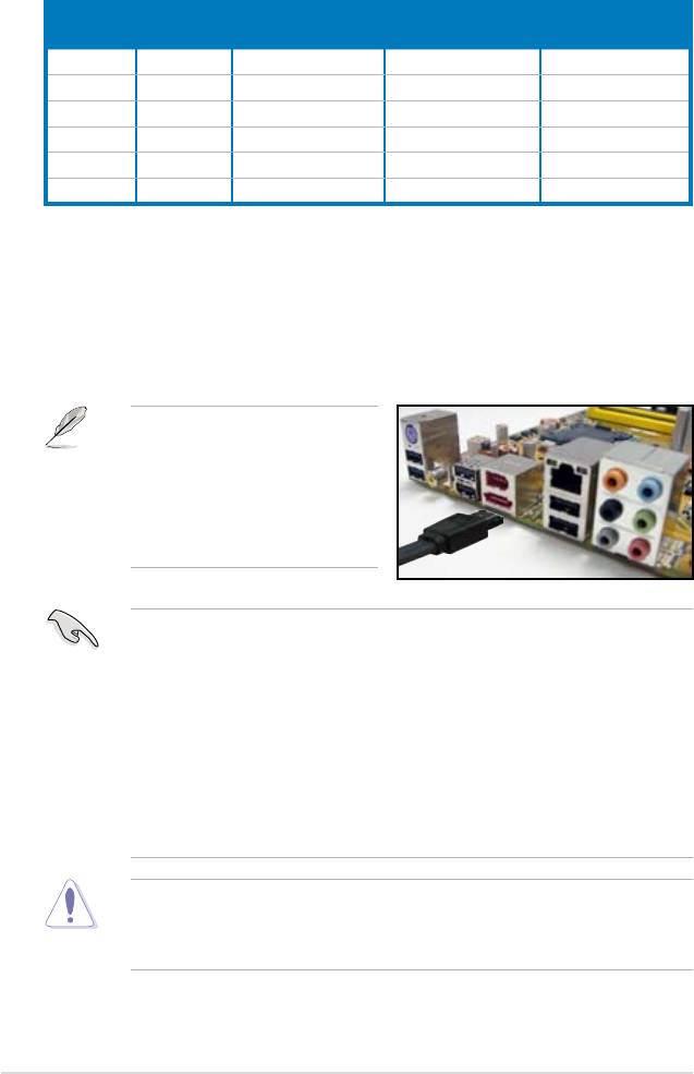
11. External SATA port. This port connects an external Serial ATA hard disk
drive. To congure a RAID 0, RAID 1, or JBOD set, install an external Serial
ATA hard disk drive and an internal Serial ATA hard disk drive connected to
the onboard Serial ATA connector labeled SATA_E2.
The external SATA port supports
external Serial ATA 3.0 Gb/s
devices. Longer cables support
higher power requirements to
deliver signal up to two meters
away, and enables improved hot-
swap function.
• Before creating a RAID set using Serial ATA hard disks, make sure that you
have connected the Serial ATA signal cable and installed Serial ATA hard
disk drives; otherwise, you cannot enter the JMicron RAID utility and SATA
BIOS setup during POST.
• If you intend to create a RAID conguration using this connector, set the
JMicron eSATA/PATA Controller Mode item in the BIOS to [RAID]. Setting
this item to [AHCI] supports Native Command Queuing (NCQ) function.
See section 4.4.5 Onboard Devices Conguration for details.
• Refer to section
5.4 RAID congurations for details about conguring a
RAID 0, RAID 1, or JBOD.
• DO NOT insert a different connector to this port.
• DO NOT unplug the external Serial ATA box when a RAID 0 or JBOD is
congured.
2-26 Chapter 2: Hardware information

12. USB 2.0 ports 3 and 4. These two 4-pin Universal Serial Bus (USB) ports
are available for connecting USB 2.0 devices.
13. Coaxial S/PDIF Out port.
This port connects an external audio output device
via a coaxial S/PDIF cable.
14. USB 2.0 ports 5 and 6.
These two 4-pin Universal Serial Bus (USB) ports
are available for connecting USB 2.0 devices.
ASUS P5K 2-27

2.7.2 Internal connectors
1. Floppy disk drive connector (34-1 pin FLOPPY)
This connector is for the provided oppy disk drive (FDD) signal cable. Insert
one end of the cable to this connector, then connect the other end to the
signal connector at the back of the oppy disk drive.
Pin 5 on the connector is removed to prevent incorrect cable connection when
using a FDD cable with a covered Pin 5.
2-28 Chapter 2: Hardware information
®
FLOPPY
NOTE: Orient the red markings on
the floppy ribbon cable to PIN 1.
P5K
PIN 1
P5K Floppy disk drive connector
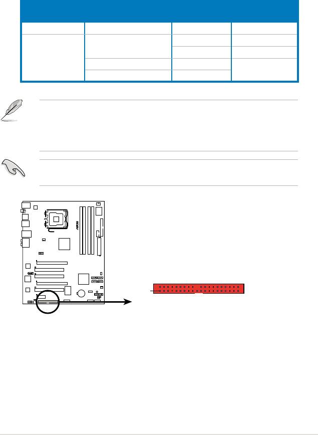
2. IDE connector (40-1 pin PRI_EIDE)
The onboard IDE connector is for the Ultra DMA 133/100/66 signal cable.
There are three connectors on each Ultra DMA 133/100/66 signal cable:
blue, black, and gray. Connect the blue connector to the motherboard’s IDE
connector, then select one of the following modes to congure your device.
Drive jumper setting Mode of
Cable connector
device(s)
Single device Cable-Select or Master - Black
Black
Two devices Cable-Select Master
Slave Gray
Master Master Black or gray
Slave Slave
• Pin 20 on the IDE connector is removed to match the covered hole on the
Ultra DMA cable connector. This prevents incorrect insertion when you
connect the IDE cable.
• Use the 80-conductor IDE cable for Ultra DMA 133/100/66 IDE devices.
If any device jumper is set as “Cable-Select,” make sure all other device
jumpers have the same setting.
ASUS P5K 2-29
®
P5K
PRI_EIDE
PIN 1
NOTE: Orient the red markings
(usually zigzag) on the IDE
ribbon cable to PIN 1.
P5K IDE connector
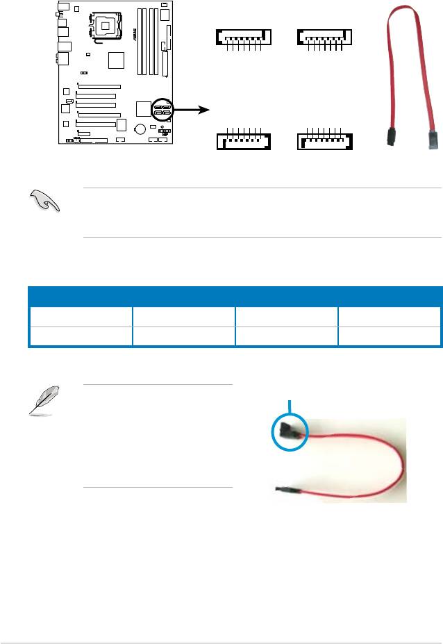
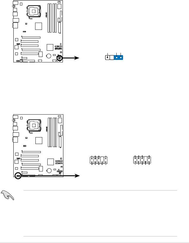
3. ICH9 Serial ATA connectors
(7-pin SATA1 [red], SATA2 [red], SATA3 [black], SATA4 [black])
These connectors are for the Serial ATA signal cables for Serial ATA hard disk
drives.
When using the connectors in Standard IDE mode, connect the primary (boot)
hard disk drive to the SATA1/2 connector. Refer to the table below for the
recommended SATA hard disk drive connections.
Serial ATA hard disk drive connection
Connector Color Setting Use
SATA 1/2 Red Master Boot disk
SATA 3/4 Black Slave Data disk
right angle side
Connect the right-angle side
of SATA signal cable to SATA
device. Or you may connect the
right-angle side of SATA cable to
the onboard SATA port to avoid
mechanical conict with huge
graphics cards.
2-30 Chapter 2: Hardware information
SATA2
SATA1
P5B
GND
RSATA_RXN2
RSATA_RXP2
GND
RSATA_TXN2
RSATA_TXP2
RSATA_RXN1
GND
RSATA_RXP1
GND
RSATA_TXN1
RSATA_TXP1
GND
GND
R
SATA3
SATA4
RSATA_TXP3
GND
GND
RSATA_RXN4
RSATA_RXP4
RSATA_TXN4
RSATA_TXN3
RSATA_TXP4
GND
GND
RSATA_RXN3
RSATA_RXP3
GND
GND
P5B SATA Connectors
SATA2
SATA1
®
GND
RSATA_TXP2
RSATA_TXN2
GND
RSATA_RXP2
RSATA_RXN2
GND
GND
RSATA_TXP1
RSATA_TXN1
GND
RSATA_RXP1
RSATA_RXN1
GND
P5K
RSATA_RXN4
RSATA_RXP4
RSATA_TXN4
RSATA_TXP4
RSATA_RXN3
RSATA_RXP3
RSATA_TXN3
RSATA_TXP3
GND
GND
GND
GND
GND
GND
P5K SATA connectors
SATA4
SATA3
®
4. JMicron JMB363
Serial ATA RAID connector (7-pin SATA_E2)
This connector is for a Serial ATA signal cable that supports a Serial ATA hard
disk drive. To congure RAID 0, RAID 1, or JBOD, install an internal Serial
ATA hard disk drive to this connector and an external Serial ATA drive to the
external SATA port.
The JMicron controller mode item in the BIOS is set to [IDE] by default. Setting
this item to [RAID] allows you to use the connectors to build a RAID set. See
®
section 5.4.2 JMicron
RAID Conguration for details. Setting this item to
[AHCI] supports Native Command Queuing (NCQ) function. See section 4.4.5
Onboard Devices Conguration for details.
Before creating a RAID set using Serial ATA hard disks, make sure that you
have connected the Serial ATA signal cables and installed Serial ATA hard disk
®
drives; otherwise, you cannot enter the JMicron
JMB363 RAID utility and SATA
BIOS setup during POST.
ASUS P5K 2-31
®
SATA_E2
P5K
GND
RSATA_TXP2
RSATA_TXN2
GND
RSATA_RXP2
RSATA_RXN2
GND
P5K SATA connector
5. Digital audio connector (4-1 pin SPDIF_OUT)
This connector is for an additional Sony/Philips Digital Interface (S/PDIF)
port(s). Connect the S/PDIF Out module cable to this connector, then install
the module to a slot opening at the back of the system chassis.
The S/PDIF module is purchased separately.
®
SPDIF_OUT
P5K
+5V
SPDIFOUT
GND
P5K Digital audio connector
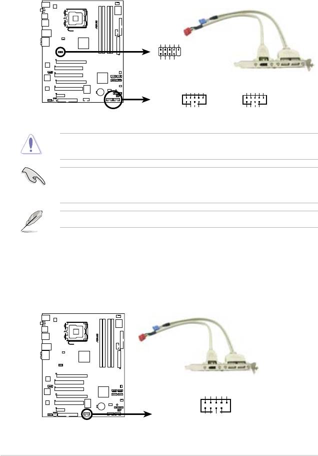
6. USB connectors (10-1 pin USB78, USB 910, USB1112)
These connectors are for USB 2.0 ports. Connect the USB module cable
to any of these connectors, then install the module to a slot opening at the
back of the system chassis. These USB connectors comply with USB 2.0
specication that supports up to 480 Mbps connection speed.
Never connect a 1394 cable to the USB connectors. Doing so will damage the
motherboard!
2-32 Chapter 2: Hardware information
®
USB1112
USB+5V
USB_P12-
USB_P12+
GND
NC
P5K
GND
USB+5V
USB_P11-
USB_P11+
USB+5V
USB_P6-
USB_P6+
GND
NC
USB+5V
USB_P8-
USB_P8+
GND
NC
USB910
USB78
P5K USB 2.0 connectors
GND
GND
USB+5V
USB_P5-
USB+5V
USB_P5+
USB_P7-
USB_P7+
7. IEEE 1394a port connector (10-1 pin IE1394_2)
This connector is for a IEEE 1394a port. Connect the IEEE 1394a module
cable to this connector, then install the module to a slot opening at the back
of the system chassis.
®
P5K
TPA1-
TPB1-
GND
+12V
GND
IE1394_2
PIN 1
TPA1+
GND
TPB1+
+12V
P5K IEEE 1394a connector
You can connect the front panel USB cable to the ASUS Q-Connector (USB,
blue) rst, and then install the Q-Connector (USB) to the USB connector
onboard if your chassis supports front panel USB ports.
The USB module cable is purchased separately.
8. Optical drive audio connector (4-pin CD)
These connectors allow you to receive stereo audio input from sound sources
such as a CD-ROM, TV tuner, or MPEG card.
ASUS P5K 2-33
®
CD
P5K
Left Audio Channel
Ground
Ground
Right Audio Channel
P5K Internal audio connector
Never connect a USB cable to the IEEE 1394a connector. Doing so will damage
the motherboard!
You can connect the front panel 1394 cable to the ASUS Q-Connector (1394,
red) rst, and then install the Q-Connector (1394) to the 1394 connector
onboard if your chassis supports front panel 1394 ports.
The IEEE 1394a module cable is purchased separately.
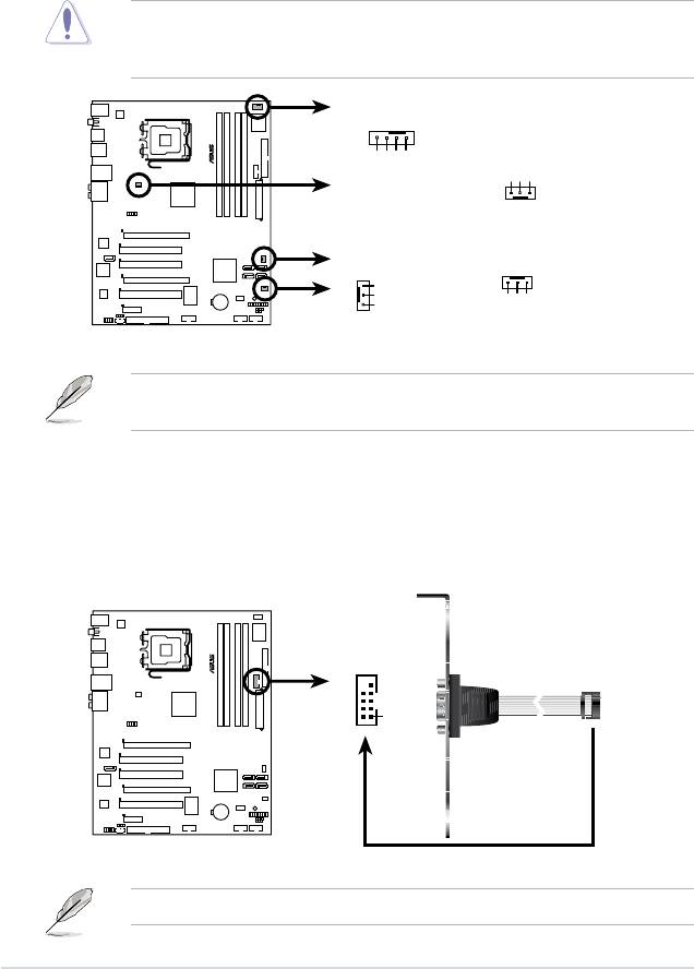
9. CPU, chassis, and power fan connectors
(4-pin CPU_FAN, 3-pin CHA_FAN1, 3-pin CHA_FAN2, 3-pin PWR_FAN)
The fan connectors support cooling fans of 350 mA~2000 mA (24 W max.)
or a total of 1 A~7 A (84 W max.) at +12V. Connect the fan cables to the fan
connectors on the motherboard, making sure that the black wire of each
cable matches the ground pin of the connector.
Do not forget to connect the fan cables to the fan connectors. Insufcient air
ow inside the system may damage the motherboard components. These are
not jumpers! Do not place jumper caps on the fan connectors!
Only the CPU-FAN and CHA-FAN 1-2 connectors support the ASUS Q-FAN 2
feature.
2-34 Chapter 2: Hardware information
CPU_FAN CHA_FAN1
Rotation
®
+12V
CPU FAN PWM
CPU FAN IN
CPU FAN PWR
GND
GND
P5K
CHA_FAN2PWR_FAN
GND
+12V
Rotation
+12V
GND
Rotation
P5K Fan connectors
10. Serial port connector (10-1 pin COM1)
This connector is for a serial (COM) port. Connect the serial port module
cable to this connector, then install the module to a slot opening at the back
of the system chassis.
®
COM1
PIN 1
P5K
P5K COM port connector
The serial port module is purchased separately.
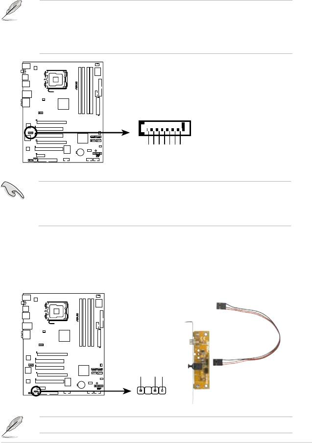
11. Chassis intrusion connector (4-1 pin CHASSIS)
This connector is for a chassis-mounted intrusion detection sensor or switch.
Connect one end of the chassis intrusion sensor or switch cable to this
connector. The chassis intrusion sensor or switch sends a high-level signal to
this connector when a chassis component is removed or replaced. The signal
is then generated as a chassis intrusion event.
By default, the pin labeled “Chassis Signal” and “Ground” are shorted with
a jumper cap. Remove the jumper caps only when you intend to use the
chassis intrusion detection feature.
ASUS P5K 2-35
®
Chassis Signal
+5VSB_MB
P5K
GND
CHASSIS
(Default)
P5K Chassis intrusion connector
12. Front panel audio connector (10-1 pin AAFP)
This connector is for a chassis-mounted front panel audio I/O module that
supports either HD Audio or legacy AC`97 audio standard. Connect one end
of the front panel audio I/O module cable to this connector.
•
We recommend that you connect a high-denition front panel audio module
to this connector to avail of the motherboard’s high-denition audio capability.
•
If you want to connect a high-denition front panel audio module to this
connector, set the Front Panel Type item in the BIOS setup to [HD Audio];
if you want to connect an AC'97 front panel audio module to this connector,
set the item to [AC'97]. By default, this connector is set to [HD Audio]. See
section 4.4.5 Onboard Devices Conguration for details.
AAFP
®
HD Audio-compliant
Legacy AC ‘97 audio
pin definition
pin definition
SENSE1_RETUR
SENSE2_RETUR
AGND
P5K
GND
NC
NC
PORT1 L
PORT1 RPRESENCE#
PORT2 R
SENSE_SEND
PORT2 L
MIC2
MICPWRNC
Line out_R
NC
Line out_L
P5K Analog front panel connector
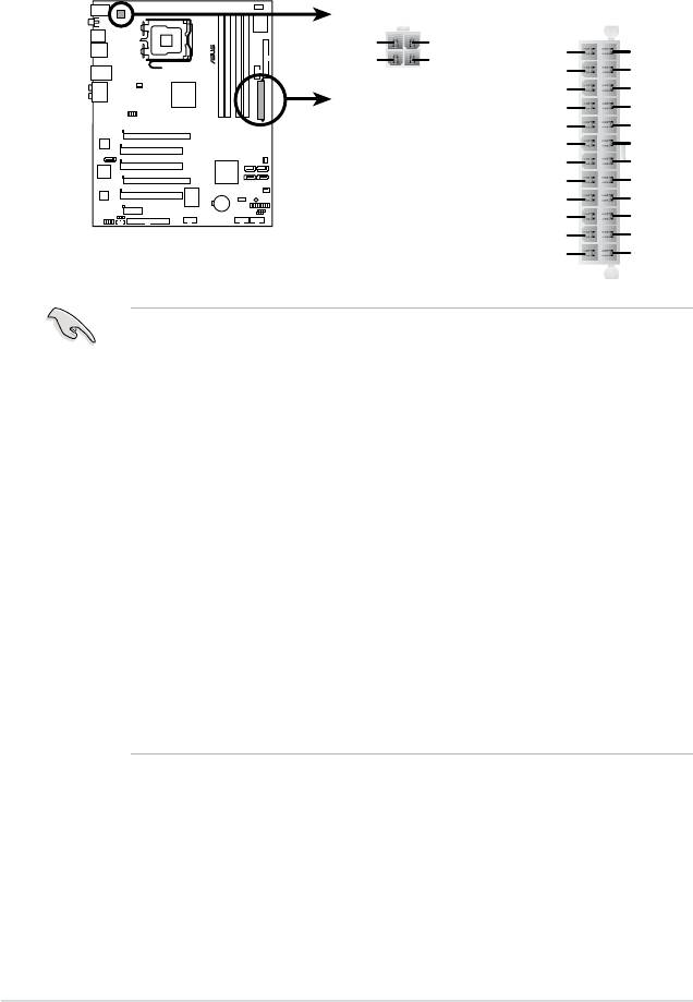
13. ATX power connectors (24-pin EATXPWR, 4-pin EATX12V)
These connectors are for ATX power supply plugs. The power supply plugs
are designed to t these connectors in only one orientation. Find the proper
orientation and push down rmly until the connectors completely t.
•
For a fully congured system, we recommend that you use a power supply
unit (PSU) that complies with ATX 12 V Specication 2.0 (or later version)
and provides a minimum power of 400 W.
• Do not forget to connect the 4-pin EATX12V power plug; otherwise, the
system will not boot.
• Use of a PSU with a higher power output is recommended when
conguring a system with more power-consuming devices. The system
may become unstable or may not boot up if the power is inadequate.
• The ATX 12 V Specication 2.0-compliant (400W) PSU has been tested
to support the motherboard power requirements with the following
conguration:
®
®
CPU: Intel
Pentium
Extreme 3.73GHz
Memory: 512 MB DDR2 (x4)
Graphics card: ASUS EAX1900XT
Parallel ATA device: IDE hard disk drive
Serial ATA device: SATA hard disk drive (x2)
Optical drive: DVD-RW
• If you want to use two high-end PCI Express x16 cards, use a PSU with
500W to 600W power or above to ensure the system stability.
2-36 Chapter 2: Hardware information
ATX12V
EATXPWR
®
+12V DC
+12V DC
+3 Volts
Ground
GND
GND
+12 Volts
+5 Volts
+12 Volts
+5 Volts
+5V Standby
+5 Volts
P5K
Power OK
-5 Volts
Ground
Ground
+5 Volts
Ground
Ground
Ground
+5 Volts
PSON#
Ground
Ground
+3 Volts
-12 Volts
P5K ATX power connectors
+3 Volts
+3 Volts
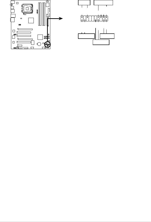
14. System panel connector (20-8 pin PANEL)
This connector supports several chassis-mounted functions.
•
System power LED (2-pin PLED)
This 2-pin connector is for the system power LED. Connect the chassis
power LED cable to this connector. The system power LED lights up when
you turn on the system power, and blinks when the system is in sleep mode.
•
Hard disk drive activity LED (2-pin IDE_LED)
This 2-pin connector is for the HDD Activity LED. Connect the HDD Activity
LED cable to this connector. The IDE LED lights up or ashes when data is
read from or written to the HDD.
•
System warning speaker (4-pin SPEAKER)
This 4-pin connector is for the chassis-mounted system warning speaker. The
speaker allows you to hear system beeps and warnings.
•
ATX power button/soft-off button (2-pin PWRSW)
This connector is for the system power button. Pressing the power button
turns the system on or puts the system in sleep or soft-off mode depending
on the BIOS settings. Pressing the power switch for more than four seconds
while the system is ON turns the system OFF.
•
Reset button (2-pin RESET)
This 2-pin connector is for the chassis-mounted reset button for system
reboot without turning off the system power.
ASUS P5K 2-37
PLED SPEAKER
®
PLED+
PLED-
+5V
Ground
Ground
Speaker
PANEL
P5K
PWR
Reset
Ground
Ground
IDE_LED+
IDE_LED-
IDE_LED
RESET
PWRSW
* Requires an ATX power supply.
P5K System panel connector
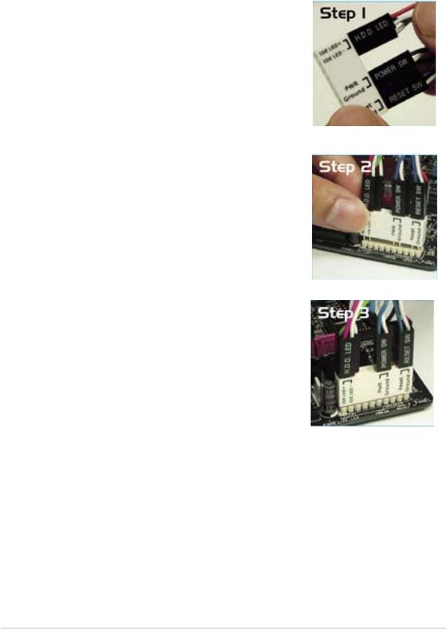
Q-Connector (system panel)
You can use ASUS Q-Connector to connect / disconnect chassis front panel
cables by only a few steps. Directions below shows how to install ASUS Q-
Connector.
Step1.
Connect correct front panel to ASUS Q-
Connector rst. You can refer to the marking
on Q-Connector itself to know the detail pin
denition.
Step2.
Properly install the ASUS Q-Connector to the
System panel connctor.
Step3.
Front panel functions are enabled.
2-38 Chapter 2: Hardware information
