Asus P4V533-MX – страница 2
Инструкция к Материнской Плате Asus P4V533-MX
®
®
®
®
1-11
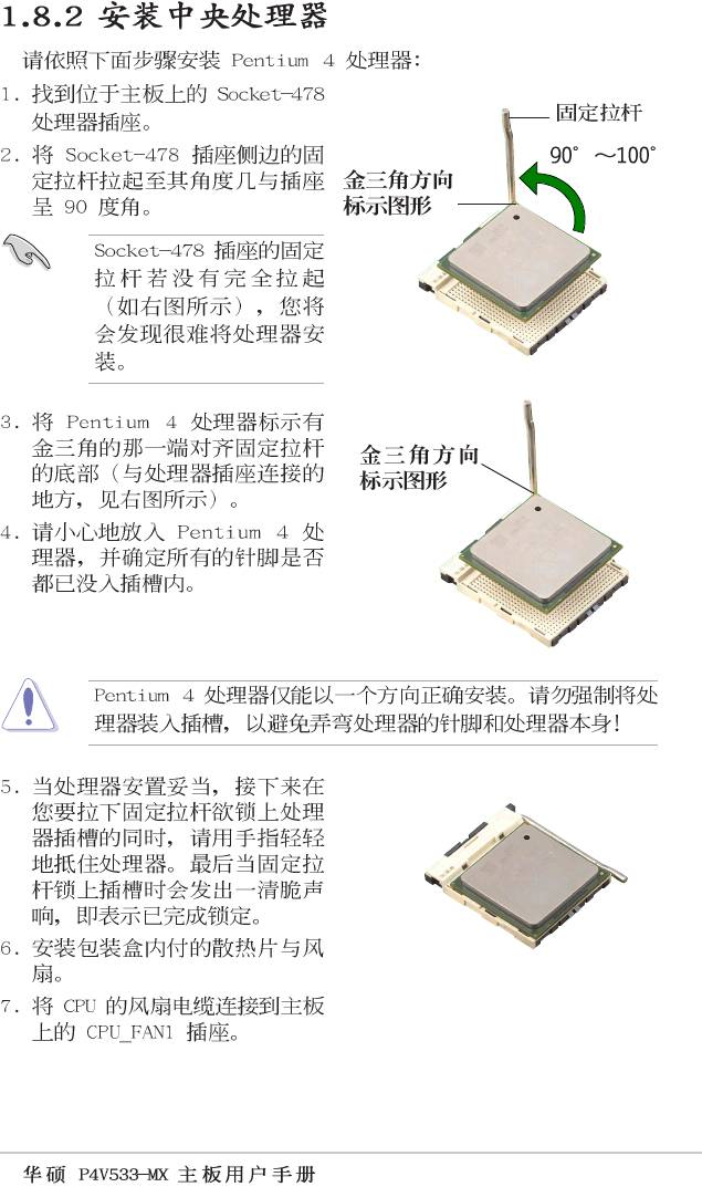
104 Pins
®
P4V533-MX
80 Pins
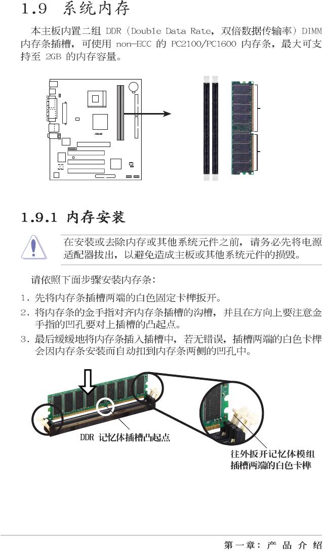
P4V533-MX 184-Pin DDR DIMM Sockets
1-12
ABCDEFGH
1-13
®
P4V533-MX
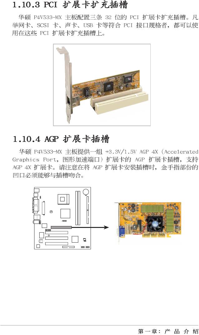
P4V533-MX Accelerated Graphics Port (AGP )
1-14
®
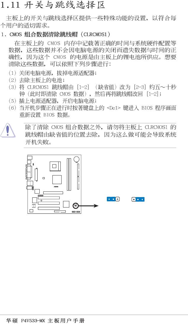
CLRCMOS1
P4V533-MX
12 23
Normal Clear CMOS
(Default)
P4V533-MX Clear RTC RAM Setting
1-15
®
P4V533-MX
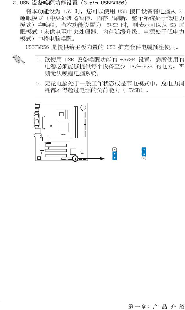
USBPWR56
3
2
2
1
+5V
+5VSB
P4V533-MX USB Device Wake Up
(Default)
1-16
®
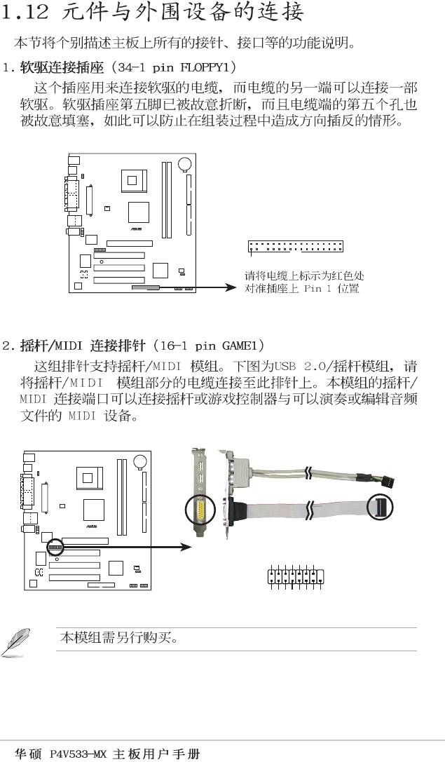
FLOPPY1
P4V533-MX
PIN 1
P4V533-MX Floppy Disk Drive Connector
®
P4V533-MX
+5V
J2B1
J2CX
MIDI_OUT
J2CY
J2B2
MIDI_IN
GAME1
P4V533-MX Smartcard
+5V
J1B1
GND
GND
J1B2
+5V
J1CX
J1CY
1-17
®
P4V533-MX
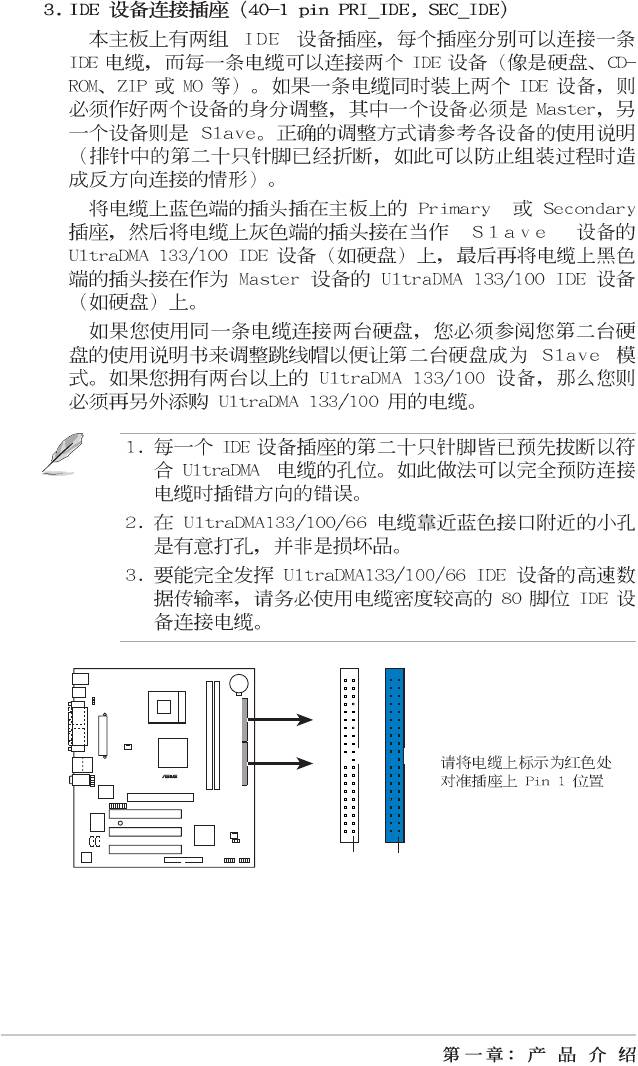
SEC_IDE
PRI_IDE
PIN 1
PIN 1
P4V533-MX IDE Connectors
1-18
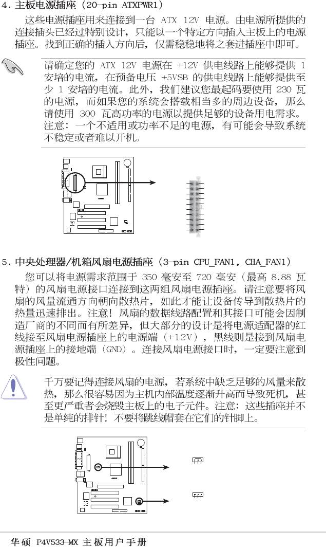
ATXPWR1
+12.0VDC
+5.0VDC
+5VSB
+5.0VDC
PWR_OK
-5.0VDC
®
COM
COM
+5.0VDC
COM
P4V533-MX
COM
COM
+5.0VDC
PS_ON#
COM
COM
+3.3VDC
-12.0VDC
+3.3VDC
+3.3VDC
P4V533-MX ATX Power Connectors
CPU_FAN1
+12V
GND
®
Rotation
CHA_FAN1
P4V533-MX
+12V
GND
Rotation
P4V533-MX 12-Volt Cooling Fan Power
1-19
®
CD1(Black)
AUX1(White)
Left Audio Channel
P4V533-MX
Ground
Ground
Right Audio Channel
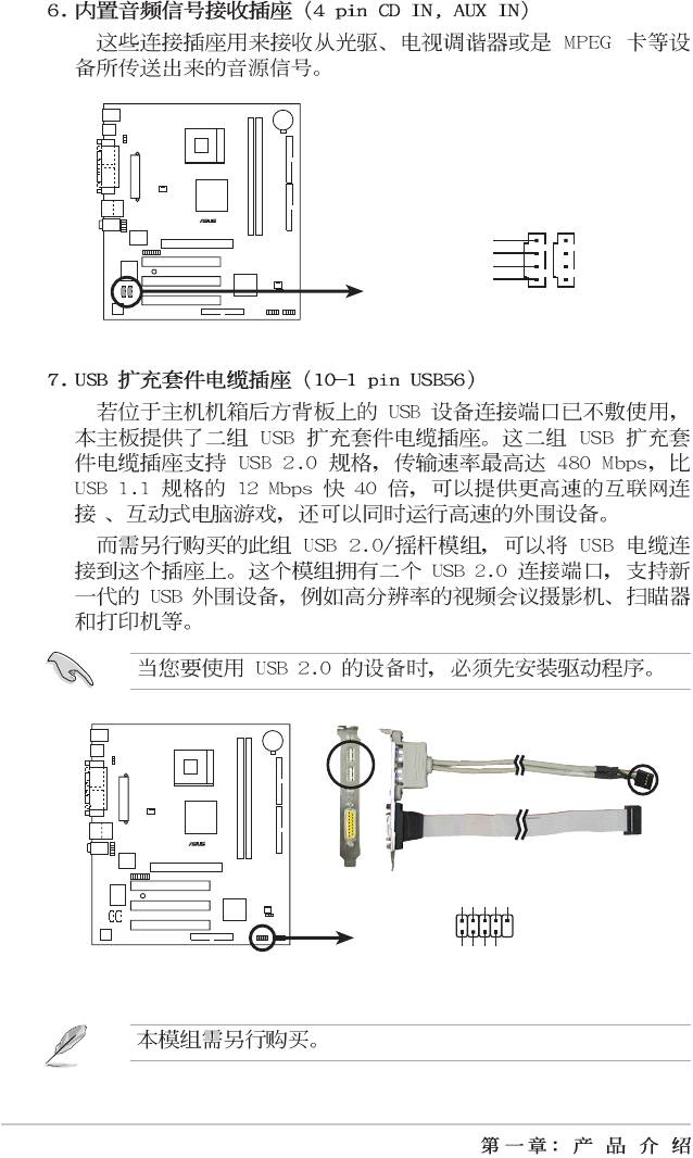
P4V533-MX Internal Audio Connectors
®
P4V533-MX
USB+5V
USB_P4-
USB_P4+
GND
NC
USB56
1
P4V533-MX USB Header
GND
USB+5V
USB_P5-
USB_P5+
1-20
®
P4V533-MX
PLED1
PLED-
NC
PLED+
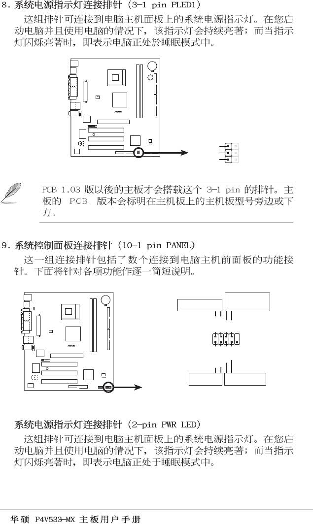
P4V533-MX Power LED
1
ATX Power
Power LED
Switch*
PLED+
PLED-
PWR
GNDReset
PANEL1
®
P4V533-MX
Ground
IDE_LED+
IDE_LED-
IDE_LED
Reset SW
*
Requires an ATX power supply.
P4V533-MX System Panel Connector
•
1-21
•
•
•
BUZZ1
®
P4V533-MX
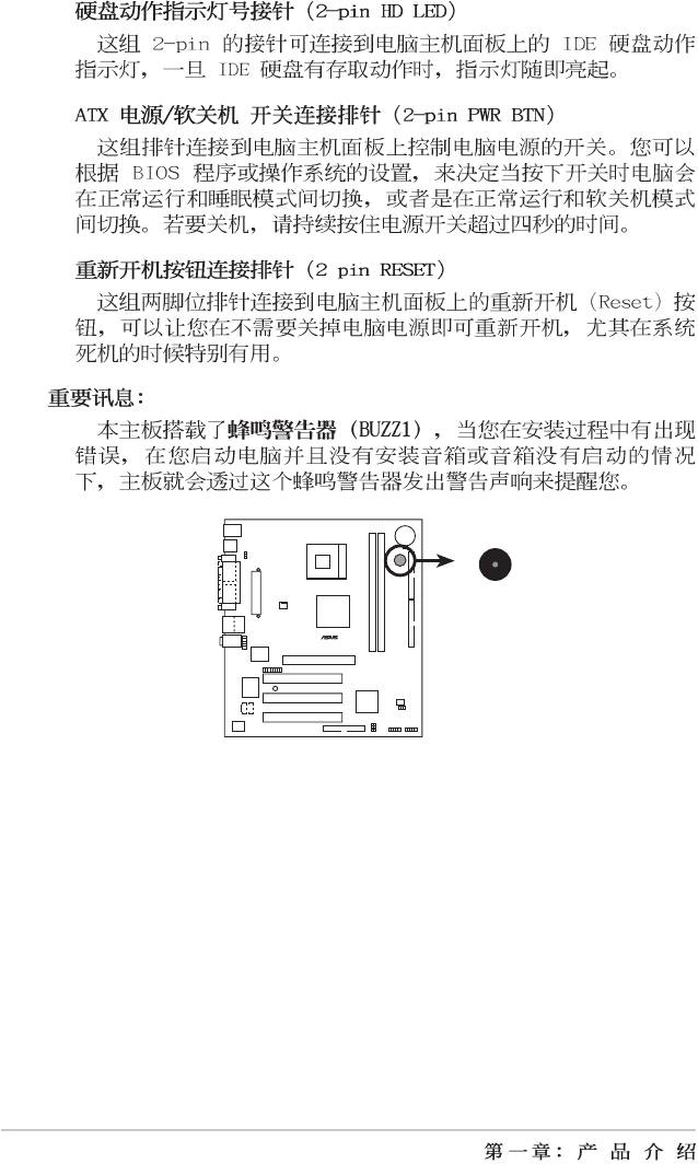
P4V533-MX Buzzer
1-22
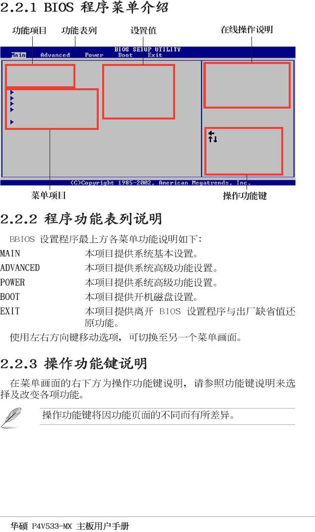
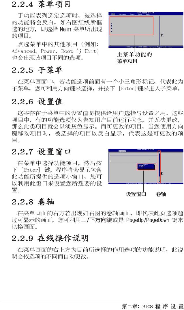
2-1
2-2
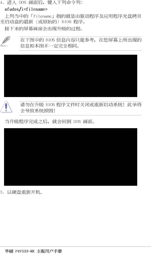
A:\>afudos /iP4V533-MX.rom
AMI Firmware Update Utility - Version 1.10
Copyright (C) 2002 American Megatrends, Inc. All rights reserved.
Reading file ..... done
Erasing flash .... done
Writing flash .... 0x0008CC00 (9%)
A:\>afudos /iP4V533-MX.rom
AMI Firmware Update Utility - Version 1.10
Copyright (C) 2002 American Megatrends, Inc. All rights reserved.
Reading file ..... done
Erasing flash .... done
Writing flash .... 0x0008CC00 (9%)
Verifying flash .. done
A:\>
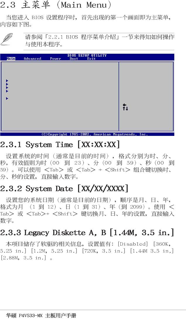
2-3
2-4
System Time [11:10:19]
Use [ENTER], [TAB]
System Date [Thu 05/27/2003]
or [SHIFT-TAB] to
Legacy Diskette A [1.44M, 3.5 in]
select a field.
Primary IDE Master :[ST320413A]
Use [+] or [-] to
Primary IDE Slave :[ASUS CD-S340]
configure system time.
Secondary IDE Master :[Not Detected]
Secondary IDE Slave :[Not Detected]
System Information
Select Screen
Select Item
+- Change Field
Tab Select Field
F1 General Help
F10 Save and Exit
ESC Exit
2-5
System Date [Thu 05/27/2003]
System Time [11:10:19]
or [SHIFT-TAB] to
Use [ENTER], [TAB]
Legacy Diskette A [1.44M, 3.5 in]
select a field.
Primary IDE Master :[ST320413A]
Primary IDE Slave :[ASUS CD-S340]
configure system time.
Use [+] or [-] to
Secondary IDE Slave :[Not Detected]
Secondary IDE Master :[Not Detected]
System Information
Select Item
Select Screen
Tab Select Field
+- Change Field
F10 Save and Exit
F1 General Help
ESC Exit
Advanced PCI/PnP settings
NO: Lets the bIOS
WARNING: Setting wrong values in the sections below
configure all the
may cause system to malfunction.
devices in the system.
PCI Latency Timer [64]
Plug and Play OS [No]
operating system
YES: Lets the
Allocate IRQ to PCI VGA [Yes]
required for boot if
Play (PnP) devices not
configure Plug and
IRQ3 [Available]
IRQ4 [Available]
your system has a Plug
IRQ5 [Available]
and Play operating
IRQ7 [Available]
system.
IRQ9 [Available]
Select Screen
IRQ10 [Available]
IRQ11 [Available]
IRQ14 [Available]
IRQ15 [Available]
ESC Exit
F10 Save and Exit
F1 General Help
+- Change Option
Select Item
2-6
System Time [11:10:19]
Use [ENTER], [TAB]
System Date [Thu 05/27/2003]
or [SHIFT-TAB] to
Legacy Diskette A [1.44M, 3.5 in]
select a field.
Primary IDE Master :[ST320413A]
Use [+] or [-] to
Primary IDE Slave :[ASUS CD-S340]
configure system time.
Secondary IDE Master :[Not Detected]
Secondary IDE Slave :[Not Detected]
System Information
Select Screen
Select Item
+- Change Field
Tab Select Field
F1 General Help
F10 Save and Exit
ESC Exit
2-7
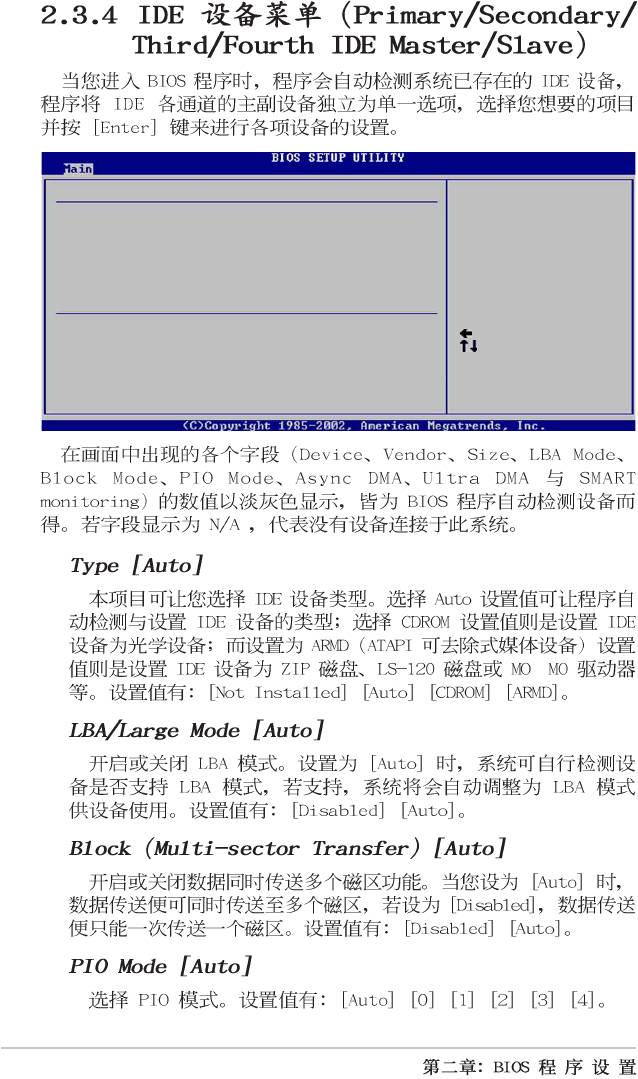
Primary IDE Master
Select the type
Device : Hard Disk
of device connected
Vendor : ST320413A
to the system.
Size : 20.0GB
LBA Mode : Supported
Block Mode : 16 Sectors
PIO Mode : 4
Async DMA : MultiWord DMA-2
SMART Monitoring: Supported
Type
[Auto]
LBA/Large Mode
[Auto]
Select Screen
Block (Multi-sector Transfer)
[Auto]
Select Item
PIO Mode
[Auto]
+- Change Option
DMA Mode
[Auto]
F1 General Help
Smart Monitoring
[Auto]
F10 Save and Exit
32Bit Data Transfer
[Disabled]
ESC Exit
