Asus P4P800: Chapter 5
Chapter 5: Asus P4P800

Chapter 5
This chapter describes the contents of the
support CD that comes with the
motherboard package.
Software support

Chapter summary
5.1 Install an operating system........................... 5-1
5.2 Support CD information ................................ 5-1
5.3 Software information ..................................... 5-7
®
5.4 Intel
RAID for Serial ATA configuration .... 5-21
®
5.5 Using Intel
Makedisk.exe........................... 5-25
®
5.6 Marvell
Virtual Cable Tester™ (VCT) ........ 5-26
ASUS P4P800 motherboard
5.1 Install an operating system
This motherboard supports Windows 98SE/ME/2000/XP operating system
(OS). Always install the latest OS version and corresponding updates so
you can maximize the features of your hardware.
Because motherboard settings and hardware options vary, use the
setup procedures presented in this chapter for general reference only.
Refer to your OS documentation for more information.
5.2 Support CD information
The support CD that came with the motherboard contains useful software
and several utility drivers that enhance the motherboard features.
The contents of the support CD are subject to change at any time
without notice. Visit the ASUS website for updates.
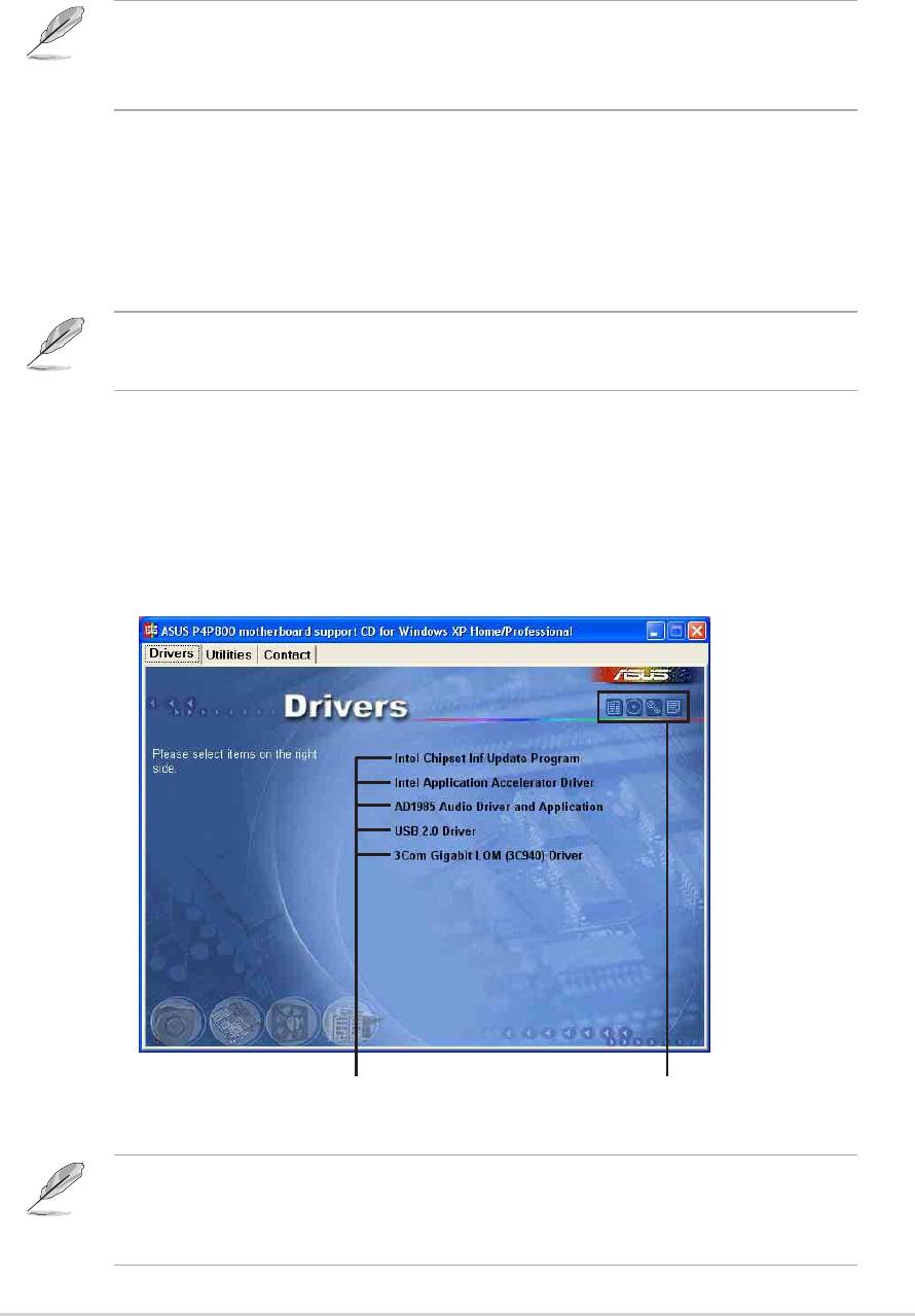
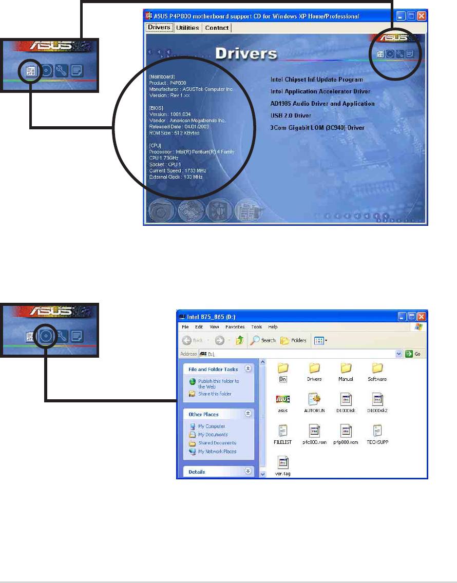
5.2.1 Running the support CD
To begin using the support CD, simply insert the CD into your CD-ROM
drive. The CD automatically displays the Drivers menu if Autorun is
enabled in your computer.
Click an item to install
Click an icon to display
more information
If Autorun is NOT enabled in your computer, browse the contents of
the support CD to locate the file ASSETUP.EXE from the BIN folder.
Double-click the ASSETUP.EXE to run the CD.
ASUS P4P800 motherboard user guide
5-1
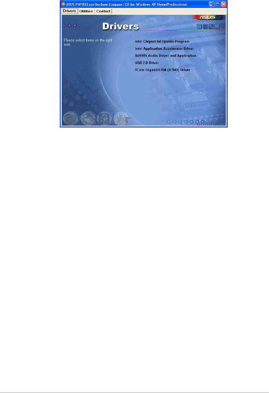
5.2.2 Drivers menu
The drivers menu shows the available device drivers if the system detects
installed devices. Install the necessary drivers to activate the devices.
Intel Chipset Inf Update Program
®
This item installs the Intel
Chipset INF Update Program that enables
®
Plug-n-Play INF support for Intel
chipset components. This utility installs
to the target system the Windows INF files that outline to the operating
system how the chipset components will be configured.
You may install this utility in three modes: interactive, silent and
unattended preload. The interactive mode requires user input during
installation. This is not required in the silent and unattended preload
modes.
Refer to the online help or readme file that came with the utility.
Intel Application Accelerator Driver
This item installs the Intel Application Accelerator Driver. If you are using
®
Windows
XP, this driver allows RAID 0 configuration for the Serial ATA
channels. This driver can only be installed when the RAID function of S-
ATA is enabled.
AD1985 Audio Driver and Applications
This item executes the wizard to install the SoundMAX audio driver and
applications.
5-2
Chapter 5: Software support
USB 2.0 Driver
This item installs the Universal Serial Bus 2.0 driver.
3Com Gigabit LOM (3C940) Driver
This item executes the dialogue box interface for the 3COM NIC driver and
diagnostics installation.
Screen display and driver options may not be the same for other
operating system versions.
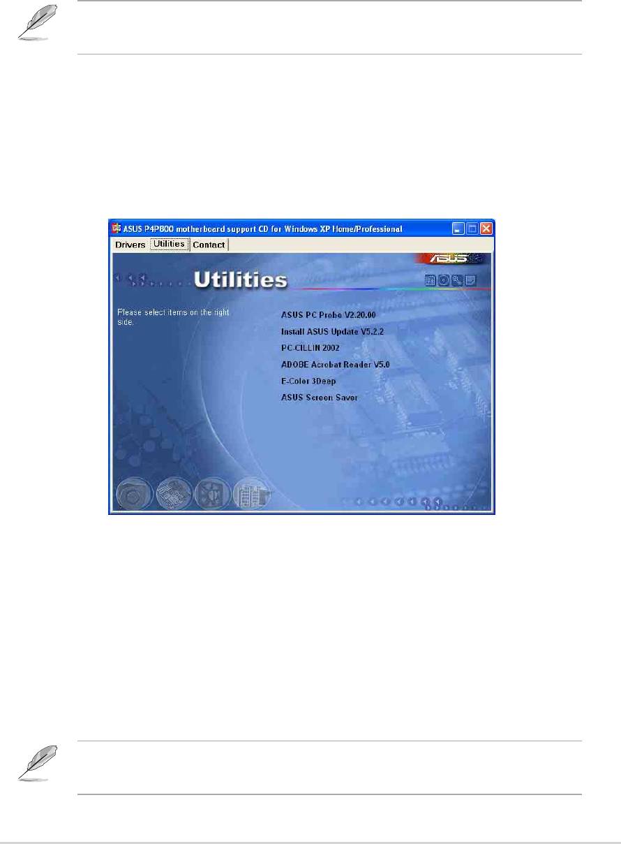
5.2.3 Utilities menu
The Utilities menu shows the applications and other software that the
motherboard supports.
ASUS PC Probe
This smart utility monitors the fan speed, CPU temperature, and system
voltages, and alerts you on any detected problems. This utility helps you
keep your computer at a healthy operating condition.
Install ASUS Update
This program allows you to download the latest version of the BIOS from
the ASUS website.
Before using the ASUS Update, make sure that you have an Internet
connection so you can connect to the ASUS website.
ASUS P4P800 motherboard user guide
5-3
Microsoft Direct X 8.1 Driver
This item installs the Microsoft V8.1 driver.
PC-CILLIN 2002
This item installs the PC-cillin 2002 anti-virus program. View the PC-cillin
online help for detailed information.
Adobe Acrobat Reader V5.0
This item installs the Adobe Acrobat Reader V5.0. The Acrobat Reader
software is for viewing files saved in Portable Document Format (PDF).
ASUS Screen Saver
This item installs the ASUS screen saver.
E-Color 3Deep
This item installs the 3Deep software. 3Deep is the first application that
gives online gamers the competitive edge in multi-player skirmishes. This
application removes dark washed-out graphics to deliver true vibrant
colors.
Screen display and utilities option may not be the same for other
operating system versions.
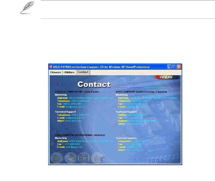
5.2.4 ASUS Contact Information
Clicking the ASUS Contact Information tab displays as stated. You may
also find this information on page x of this user guide.
5-4
Chapter 5: Software support
5.2.5 Other information
The icons on the top right corner of the screen give additional information
on the motherboard and the contents of the support CD. Click an icon to
display the specified information.
Motherboard Info
The window displays the general specifications of the P4P800
motherboard.
Browse this CD
The window displays the support CD contents in graphical format.
ASUS P4P800 motherboard user guide
5-5
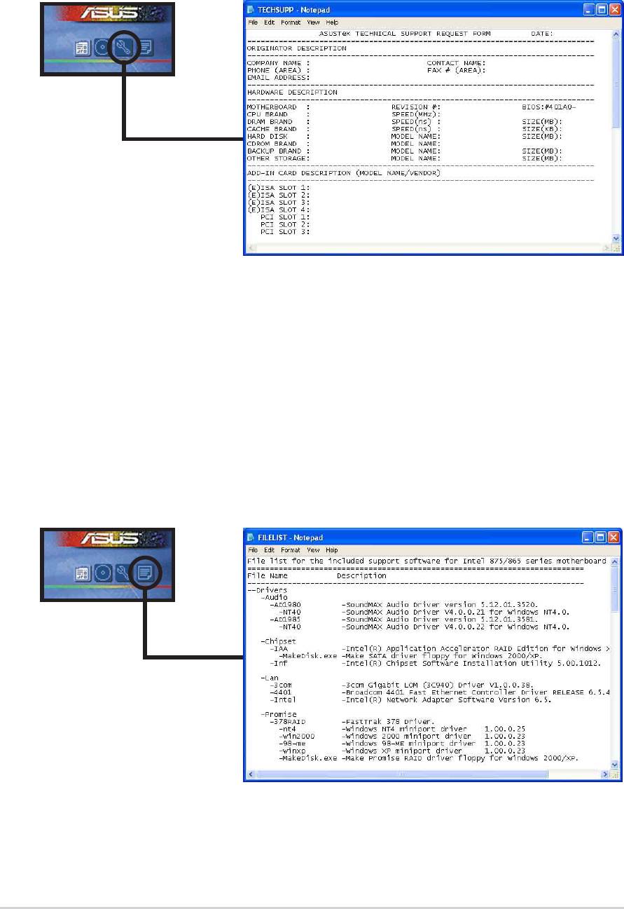
Technical Support Form
The window displays the ASUS Technical Support Request Form that you
have to fill up when requesting technical support.
Filelist
The window displays the contents of the support CD and a brief
description of each in text format.
5-6
Chapter 5: Software support
5.3 Software information
Most of the applications in the support CD have wizards that will
conveniently guide you through the installation. View the online help or
readme file that came with the software for more information.
This section provides details on the software applications that the
motherboard supports.
5.3.1 ASUS Update
The ASUS Update is a utility that allows you to update the motherboard
BIOS and drivers. This utility requires an Internet connection either
through a network or an Internet Service Provider (ISP).
Follow these steps to use the ASUS Update.
1. Launch the utility from your Windows
Start menu:
Programs/AsusUpdate Vx.xx.xx/
AsusUpdate
The ASUS Update initial screen
appears.
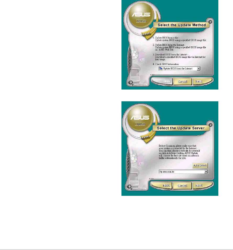
2. Select your desired update method,
then click Next.
3. If you selected updating/
downloading from the Internet,
select the ASUS FTP site nearest
you to avoid network traffic, or
choose Auto Select. Click Next.
ASUS P4P800 motherboard user guide
5-7
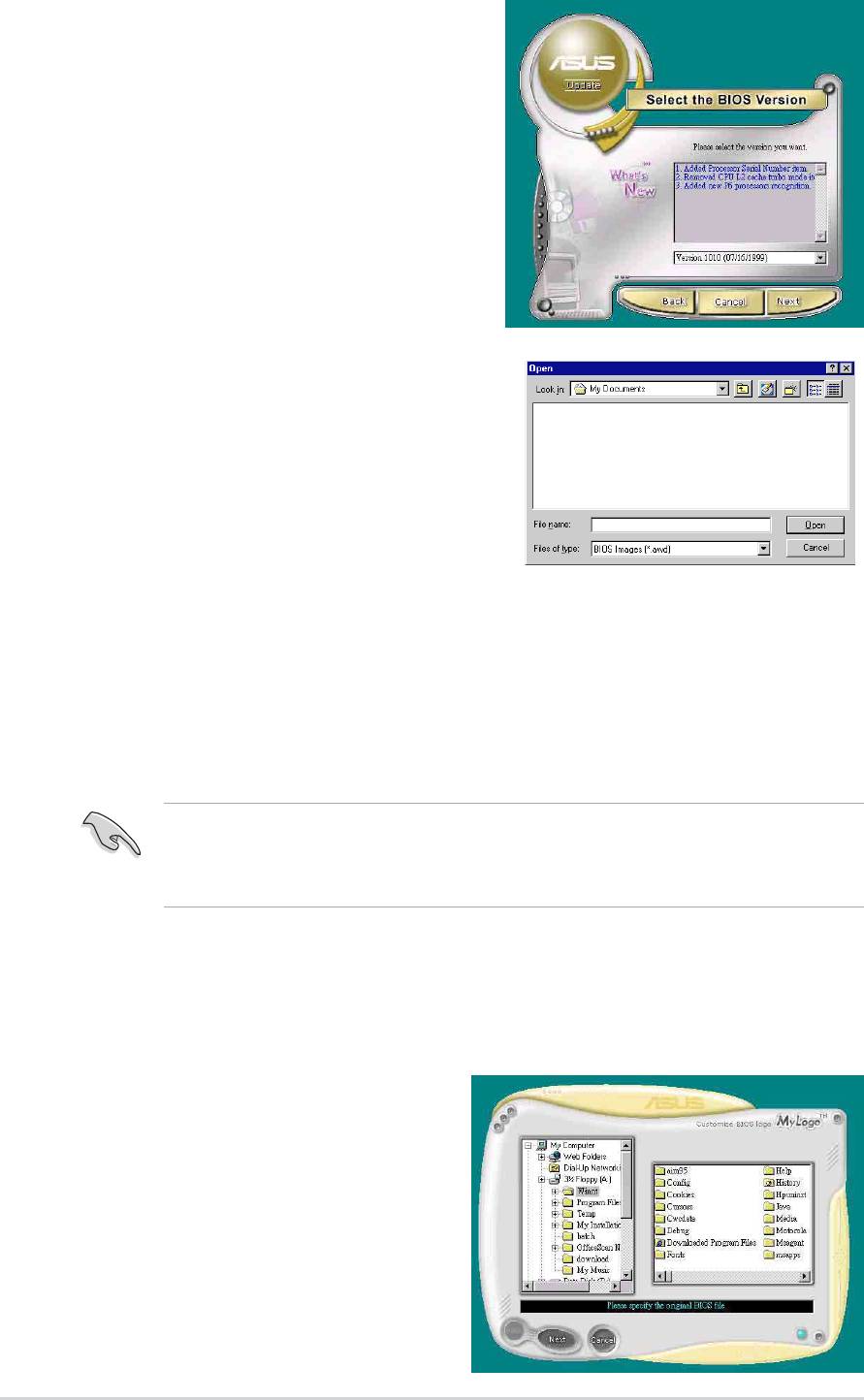
4. From the FTP site, select the
BIOS version that you wish to
download. Click Next.
5. Follow the instructions on the
succeeding screens to complete
the update process.
If you selected the option to update
the BIOS from a file, a window pops
up prompting you to locate the file.
Select the file, click Save, then follow
the screen instructions to complete
the update process.
5.3.2 ASUS MyLogo2™
The ASUS MyLogo2™ is automatically installed when you install the
ASUS Update utility from the software menu. See section “5.2.3 Utilities
menu”.
Before using ASUS MyLogo2 feature, use the AFLASH utility to make
a copy of your original BIOS file, or obtain the latest BIOS version from
the ASUS website.
Follow these steps to use ASUS MyLogo2.
1. Launch the ASUS Update utility.
See section “5.3.1 ASUS Update.”
2. When prompted for the BIOS
update method, select the option
“Update BIOS from a file.”
3. Specify the location of the BIOS
file, such as from a floppy disk.
Click Next.
5-8
Chapter 5: Software support
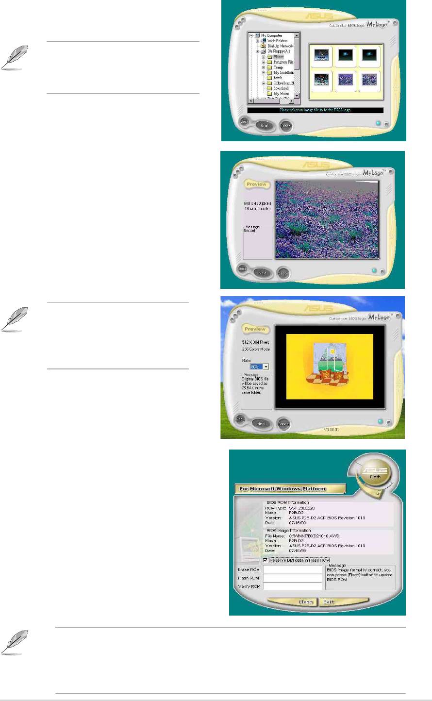
4. From the selection that appears,
choose a logo image. Click Next.
If you wish, you may create
your own boot logo image in
GIF, JPG, or BMP file formats.
5. When you click on an image, it
displays larger on the MyLogo2
screen.
If you will to make the logo
image smaller, click on the
arrow on the Ratio item and
select your desired scale.
6. The next screen prompts you to
flash the original BIOS to update
it with the new boot logo. Click
Flash to update the BIOS.
7. When finished, click Exit, then
reboot your computer.
Your system boots with the new
boot logo.
Instead of starting from ASUS Update, you may also launch ASUS
MyLogo2 directly from the Windows Start menu to change your BIOS
boot logo. After you have modified the BIOS file with the new logo, use
the ASUS Update utility to upload the new BIOS.
ASUS P4P800 motherboard user guide
5-9
5.3.3 ASUS PC Probe
The ASUS PC Probe is a convenient utility to continuously monitor your
computer system’s vital components, such as fan rotations, voltages, and
temperatures. It also has a utility that lets you review useful information
about your computer, such as hard disk space, memory usage, and CPU
type, CPU speed, and internal/external frequencies through the DMI
Explorer.
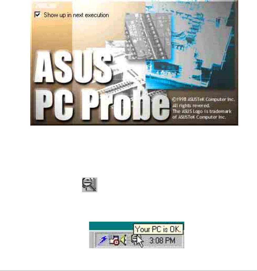
Starting ASUS PC Probe
When ASUS PC Probe starts, a splash screen appears allowing you to
select whether to show the screen again when you open PC Probe or not.
To bypass this startup screen, clear the Show up in next execution check
box.
To launch ASUS PC Probe, click the Windows Start button, point to
Programs, and then ASUS Utility, and then click Probe Vx.xx.
The PC Probe icon
appears on the taskbar system tray indicating
that ASUS PC Probe is running. Clicking the icon allows you to see the
status of your PC.
5-10
Chapter 5: Software support
Using ASUS PC Probe
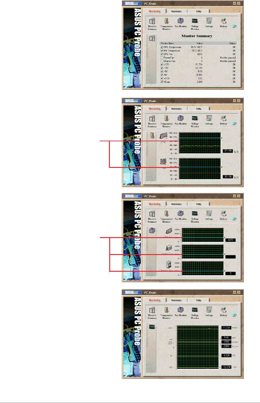
Monitoring
Monitor Summary
Shows a summary of the items
being monitored.
Temperature Monitor
Shows the PC temperature (for
supported processors only).
Temperature Warning
threshold adjustment
(Move the slider up to increase the
threshold level or down to decrease
the threshold level)
Fan Monitor
Shows the PC fan rotation.
Fan Warning
threshold adjustment
(Move the slider up to increase the
threshold level or down to decrease
the threshold level)
Voltage Monitor
Shows the PC voltages.
ASUS P4P800 motherboard user guide
5-11
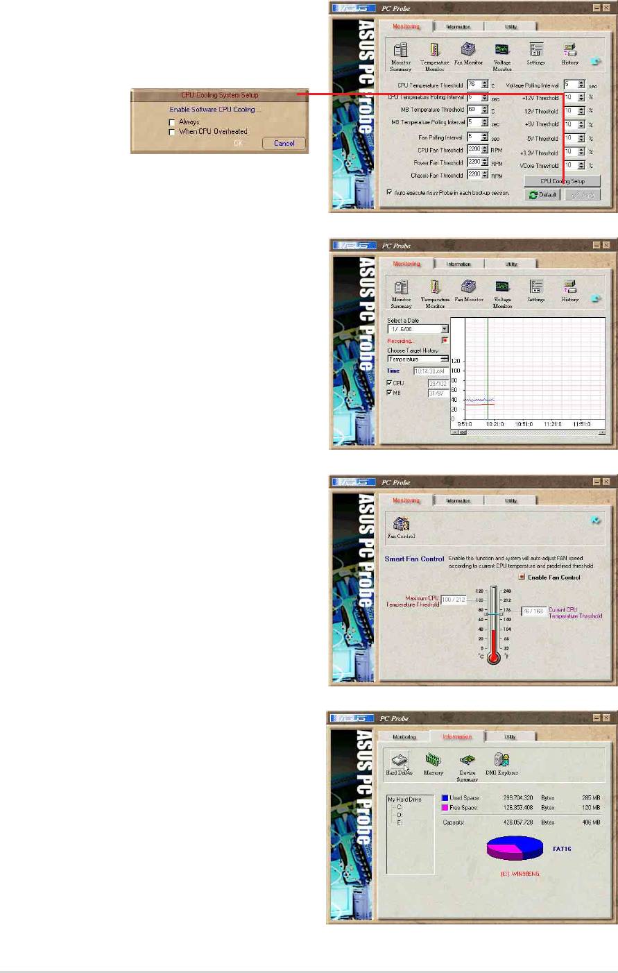
Settings
Lets you set threshold levels and
polling intervals or refresh times of
the PC’s temperature, fan rotation,
and voltages.
CPU Cooling System Setup
Lets you select when to enable software CPU
cooling. When When CPU Overheated is selected,
the CPU cooling system is enabled whenever the
CPU temperature reaches the threshold value.
History
Lets you record the monitoring
activity of a certain component of
your PC for future reference.
Fan Control
Lets you enable/disable Smart Fan
Control. Smart Fan Control adjusts
the fan speed automatically based
on the current CPU temperature
and predefined threshold.
Hard Drives
Shows the used and free space of
the PC’s hard disk drives and the
file allocation table or file system
used.
5-12
Chapter 5: Software support
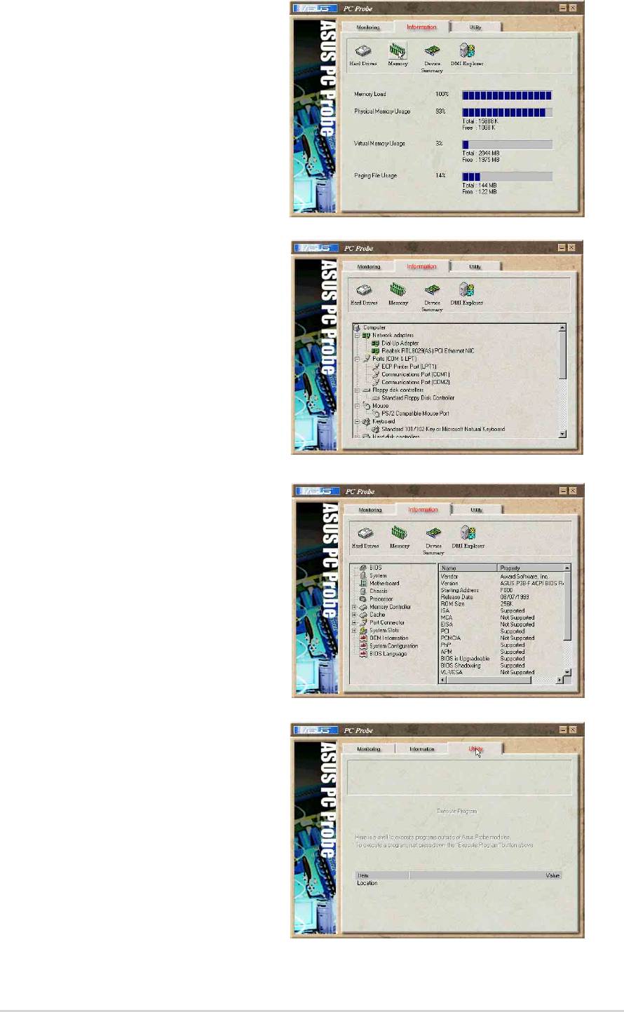
Information
Memory
Shows the PC memory load,
memory usage, and paging file
usage.
Device Summary
Shows a summary of devices
present in your PC.
DMI Explorer
Shows information pertinent to the
PC, such as CPU type, CPU
speed, and internal/external
frequencies, and memory size.
Utility
Lets you run programs outside of
the ASUS Probe modules. To run a
program, click Execute Program.
NOTE: This feature is currently
unavailable.
ASUS P4P800 motherboard user guide
5-13
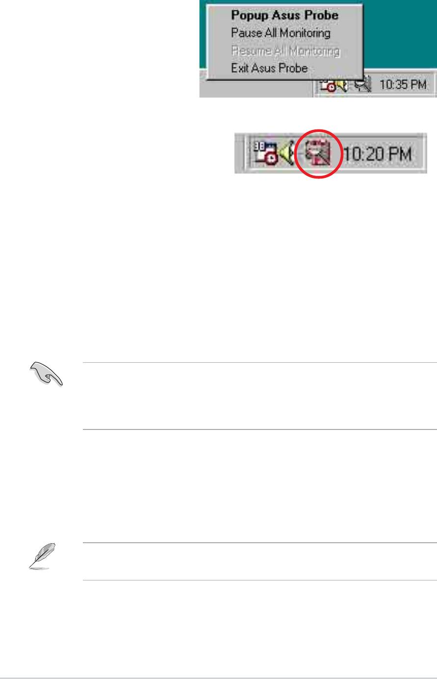
ASUS PC Probe Task Bar Icon
Right clicking the PC Probe
icon brings up a menu to
open or exit ASUS PC Probe
and pause or resume all
system monitoring.
When the ASUS PC Probe
senses a problem with your PC,
portions of the ASUS PC Probe
icon change to red, the PC
speaker beeps, and the ASUS
PC Probe monitor appears.
5.3.4 ASUS Instant Music
The ASUS Instant Music is a BIOS-based audio playback feature that
allows you to play audio CDs without turning on the system power. This
feature is supported by the onboard audio AC’97 CODEC, and requires an
optical drive (CD-ROM, DVD-ROM, or CD-RW).
1. Instant Music only supports CDs in audio format.
2. Instant Music would not work if you installed and enabled
an add-on sound card.
3. Instant Music only supports PS/2 keyboard.
To enable ASUS Instant Music:
1. Connect the analog audio cable from the optical drive (CD-ROM, DVD-
ROM, or CD-RW drive) to the 4-pin CD-In connector (labeled CD1) on
the motherboard. See section “2.8 Connectors” for the connector
location.
Make sure to connect the CD-ROM audio cable. Otherwise, you
cannot control the audio volume using the Instant Music function keys.
2. Turn on the system and enter BIOS by pressing the Delete key during
the Power On Self-Tests (POST).
3. In the Advanced Menu Instant Music Configuration menu, select
↓
the item Instant Music and set it to Enabled.
5-14
Chapter 5: Software support
4. Highlight the Instant Music CDROM item and press Enter to display
the CD-ROM options. Select the CD-ROM drive that you wish to use
for this feature.
5. Save your changes and exit BIOS Setup.
1. The Scroll Lock LED is fixed to ON after enabling Instant Music.
2. When set to Instant Music mode, the system wake-up
features (LAN, keyboard, mouse, USB) are deactivated. In
this case, power up the system using the power switch.
3. If the system lost connection or did not detect any optical
drive, the Instant Music feature turns OFF (disabled)
automatically. A “beep” indicates this condition.
To use ASUS Instant Music:
1. Ensure that the power cord is plugged to a grounded power source, so
that the system has a standby power.
2. Place the Instant Music keyboard label over Esc and other function
keys on your keyboard (top left corner). The keys covered by the label
identify the Instant Music special function keys.
Instant Music function keys (Set 1)
Esc F1 F2 F3 F4 F5 F6 F7 F8
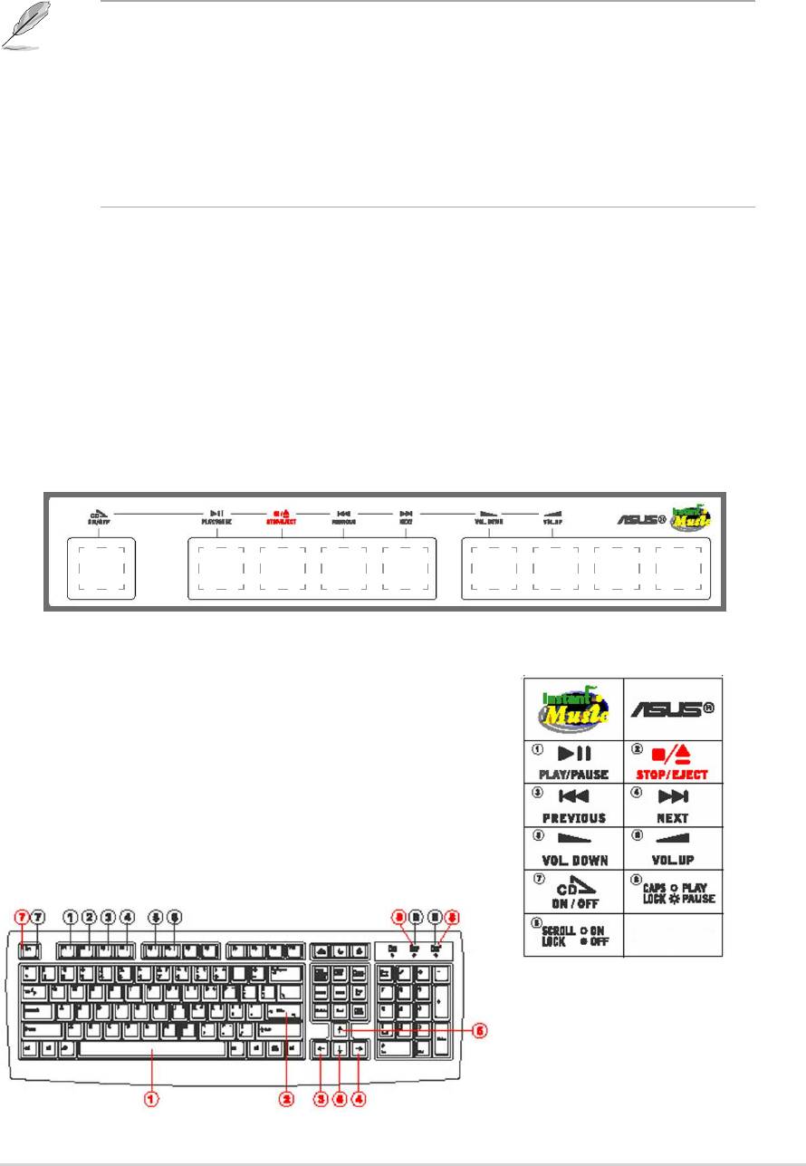
Instant Music function keys (Set 2)
As an alternative, you may also use another
set of keys on the keyboard as Instant Music
function keys. These keys are indicated by
marked numbers in the keyboard illustration
below. The functions are defined in the
illustration on the right.
↓↓↓
↓
↓
↓
↓
↓
↓
ASUS P4P800 motherboard user guide
5-15

These labels all come with your motherboard package.
3. Connect speakers or a headphone to the Line Out (lime colored) port
on the rear panel for audio output.
You may also connect a headphone to the headphone jack on the CD-
ROM drive front panel.
4. Place an audio CD on the drive.
5. Press Esc to turn ON Instant Music.
6. Press F1 or the Space Bar to play the first track on the CD.
If there is no CD on the drive and you press F1 or Space Bar, the drive
tray ejects.
7. Refer to the Instant Music function key definitions on the previous page
to select other tracks or control the volume.
8. Press F2 or Enter once to stop playing the CD.
Press F2 or Enter one more time to eject the CD.
5-16
Chapter 5: Software support
®
5.3.5 SoundMAX
4 XL software
The ADI AD1985 AC ‘97 audio CODEC provides 6-channel audio
capability through the SoundMAX4 XL with AudioESP™ software to
deliver the ultimate audio experience on your PC. The software
implements high quality audio synthesis/rendering, 3D sound positioning,
and advanced voice-input technologies.
Follow the installation wizard install the SoundMAX Audio Driver and
Application from the support CD that came with the motherboard
package to activate the 6-channel audio feature.
• You must use 4-channel or 6-channel speakers for this setup.
• SoundMAX 4 XL requires Microsoft Winodws 98SE/ME/2000/XP.
Make sure that one of these operating systems is installed before
installing SoundMAX.
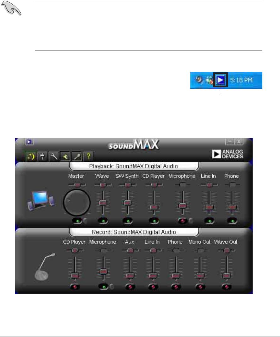
If the SoundMAX4 XL software is correctly installed,
you will find the SoundMAX4 XL icon on the
taskbar.
SoundMAX4 XL icon
From the taskbar, double-click on the SoundMAX4
XL icon to display the SoundMAX Control Panel.
ASUS P4P800 motherboard user guide
5-17
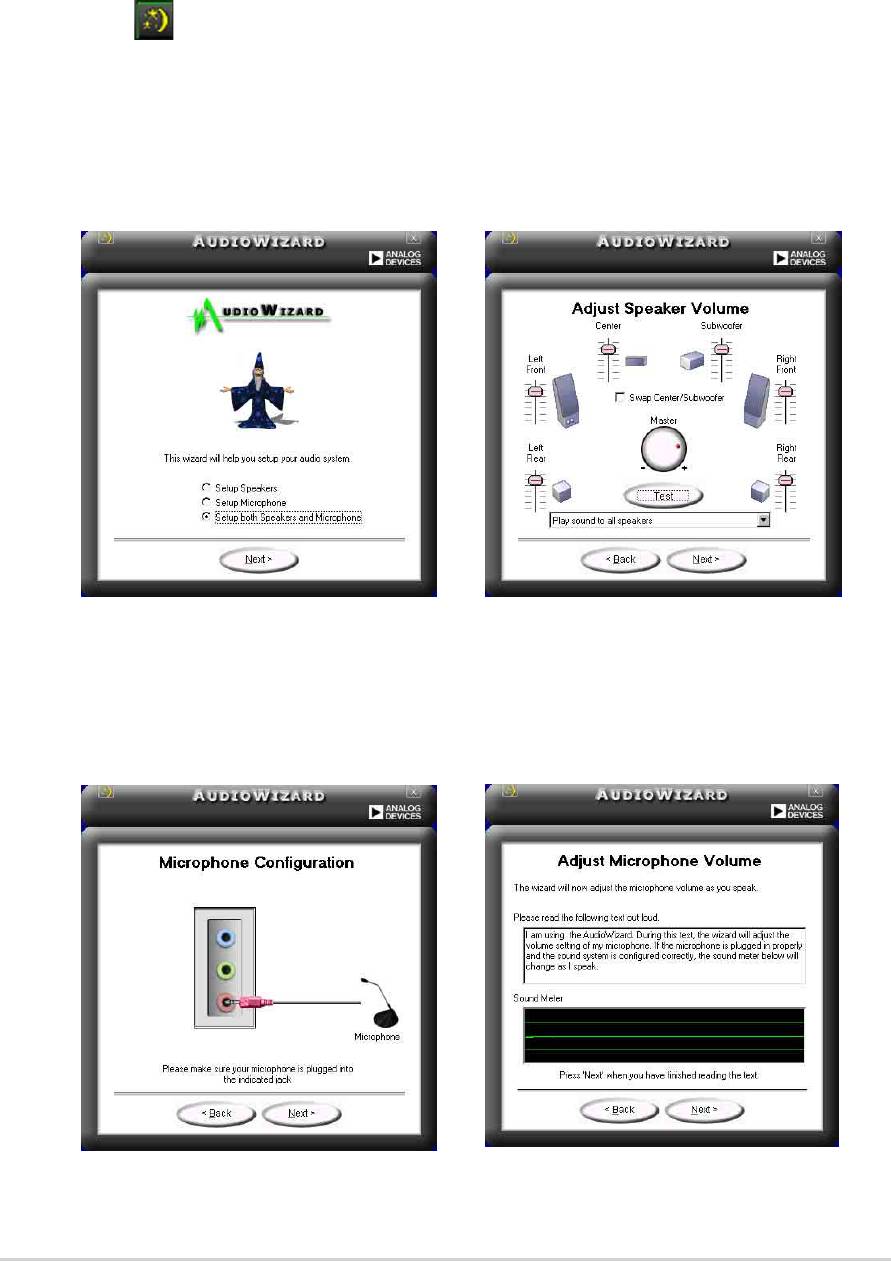
Setup wizards
Use the speaker and microphone setup wizards to fine tune the gain/
attenuation of the inputs/outputs for optimal audio performance. You may
launch the setup wizards by clicking the Configuration button when
AudioESP detects and verifies a newly connected peripheral, or by clicking
on the
icon from the SoundMAX control panel.
Speaker wizard
Follow the screen instructions to configure the speakers to your desired
settings.
Microphone wizard
Follow the screen instructions to configure the microphone to your desired
settings.
5-18
Chapter 5: Software support
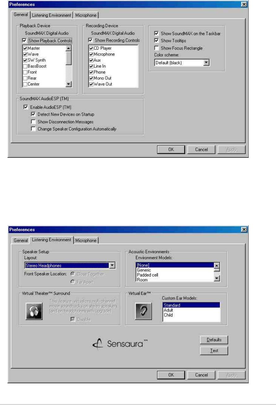
Audio preferences
The Preferences page of the SoundMAX4 XL allows you to change
various audio settings.
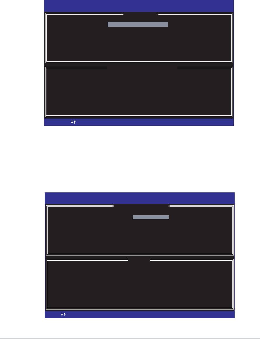
Listening environment options
The SoundMAX4 XL support several audio technologies including
SoundMAX SPX™ Animated Audio, 3DPA™, MultiDrive™ 5.1,
EnvironmentFC™, MacroFX/ZoomFX™, and Virtual Theater Surround.
ASUS P4P800 motherboard user guide
5-19

Rear panel audio ports function variation
The functions of the Line Out (lime), Line In (blue), and Mic (pink) ports on
the rear panel change when you select the 4-channel or 6-channel audio
configuration as shown in the following table.
Headphone/
2-Speaker 4-Speaker 6-Speaker
Light Blue Line In Rear Speaker Out Rear Speaker Out
Lime Line Out Front Speaker Out Front Speaker Out
Pink Mic In Mic In Bass/Center
5-20
Chapter 5: Software support

®
5.4 Intel
RAID for Serial ATA configuration
®
This motherboard supports Intel
RAID 0 for Serial ATA drives through the
®
Intel
ICH5R chipset. The Serial ATA as RAID option must be enabled in
®
the BIOS before the system can load the Intel
RAID Option ROM code for
®
®
Intel
RAID. The Intel
RAID Option ROM is a standard PnP (Plug and
Play) option ROM that provides a pre-operating system user interface for
®
the Intel
RAID implementation. It also allows the boot order to be selected
from within the BIOS setup utility.
®
For more information about the Intel
RAID for SATA configuration,
refer to the Intel Application Accelerator, RAID Edition, User’s manual
found in “\Manual\IAA RAID Manual.doc” of the support CD.
5.4.1 BIOS Configuration
1. Enter the BIOS setup program by pressing the <Del> key after the
Power-On Self Test (POST) memory test begins.
2. Select the Main menu, then the IDE Configuration menu.
3. If necessary, switch the
Onboard IDE Operate Mode option from
[Legacy Mode] to [Enhanced Mode].
4. Switch the
Configure S-ATA as RAID option to [Yes].
5. Press <F10> to save the BIOS settings and exit the BIOS
setup program.
5.4.2 Installing Serial ATA (SATA) hard disks
Installing Serial ATA (SATA) hard disks requires the use of a new SATA
data cable (4-conductor) which supports the Serial ATA protocol and a
SATA power cable. Either end of the SATA data cable can be connected to
the SATA hard disk or the SATA connector on the motherboard.
• Both the data and power SATA cables are new cables. You cannot
use older 40-pin 80-conductor IDE or regular IDE power cables
with SATA hard drives.
• Carefully follow any technical instructions that come from the hard
disk manufacturer.
Follow the given steps for correct cable installation:
1. Attach either cable end to the SATA connector on the motherboard.
2. Attach the other cable end to the SATA hard disk.
ASUS P4P800 motherboard user guide
5-21
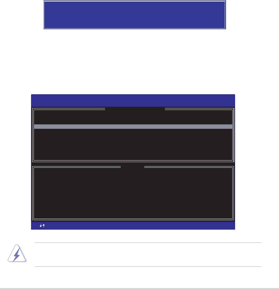
5.4.4 Creating a RAID Volume
Intel(R) Integrated RAID for Serial ATA - RAID Configuration Utility
Copyright(C) 2003 Intel Corporation. All Rights Reserved. v3.x.x.xxxx
[
CREATE ARRAY MENU
]
Name: RAID_Volume1
Strip Size: 64KB
RAID Level: RAID0(Striping)
Capacity: 37.2GB
Create Volume
[
HELP
]
Enter a string between 1 and 16 characters in length taht can be used
to uniquely identify the RAID volume. This name is case sensitive and
can not contain special characters.
[ ]-Change
5-22
Chapter 5: Software support
[ ]-Change
[TAB]-Next
[TAB]-Next
[ESC] Previous Menu
[ESC] Previous Menu
[Enter]-Select
[Enter]-Select
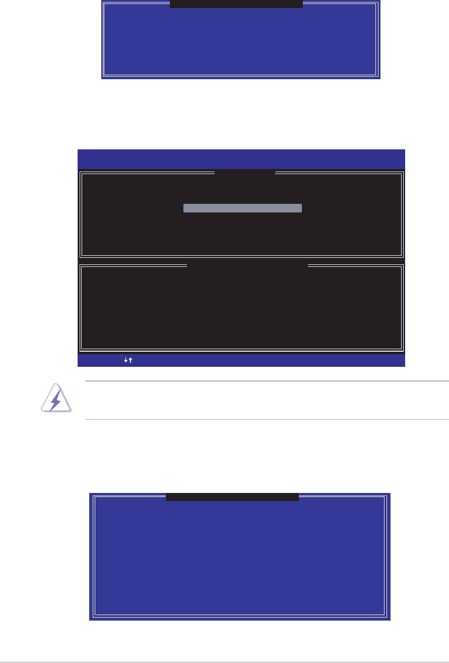
5.4.3 Creating, Deleting, and Resetting RAID Sets
The Serial ATA RAID set must be configured in the RAID Configuration
®
utility. This configuration can be done by the Intel
RAID Option ROM.
During the Power-On Self Test (POST), the following message will appear
for a few seconds: Press <Ctrl-I> to enter Raid Configuration Utility. After
this message appears, press the <Ctrl> and <I> keys simultaneously, the
following screen menu appears.
Intel(R) Integrated RAID for Serial ATA - RAID Configuration Utility
Copyright(C) 2003 Intel Corporation. All Rights Reserved. v3.x.x.xxxx
[
MAIN MENU
]
1. Create RAID Volume
2. Delete RAID Volume
3. Reset Disks to Non-RAID
4. Exit
[
DISK/VOLUME INFORMATION
]
RAID Volumes:
None defined.
Non-RAID Disks:
Port Drive Model Serial # Size Status Bootable
0 ST320413A xxxxxxxx 18.6GB Normal Yes
1 ST320413A xxxxxxxx 18.6GB Normal Yes
[ ]-Select
[ ]-Select
[ESC] Exit
[ESC] Exit
[Enter]-Select Menu
[Enter]-Select Menu
Follow the given steps to create a RAID 0 Volume
1. Select option 1 Create RAID Volume and press the <Enter> key.
2. Select the stripe value for the RAID 0 array by scrolling through the
available values by using the Up and Down arrow keys and
pressing the <Enter> key.
3. The available values range from 8 KB to 128 KB increments. The
strip value should be chosen based on the planned drive usage.
Some suggested selections are listed below. The default selection
is 64 KB.
• 16 KB - low disk usage
• 64 KB - typical disk usage
• 128 KB - performance disk usage
4. Press the <Enter> key again to the Create Volume prompt to create
the array. Confirm this selection by pressing the <Y> key after the
prompt.
Are you sure you want to create this volume (Y/N)
5. Scroll to option 4 Exit and press the <Enter> key to exit the RAID
configuration utility. Confirm the exit by pressing <Y> key.
5.4.5 Deleting a RAID Volume
Intel(R) Integrated RAID for Serial ATA - RAID Configuration Utility
Copyright(C) 2003 Intel Corporation. All Rights Reserved. v3.x.x.xxxx
[
DELETE ARRAY MENU
]
[
HELP
]
Deleting a volume will destroy the volume data on the drive(s) and
cause any member disks to become available as non-RAID disks.
WARNING:EXISTING DATA WITHING THIS VOLUME WILL BE LOST AND NON-RECOVERABLE
[ ]-Change
ASUS P4P800 motherboard user guide
5-23
[ ]-Change
[TAB]-Next
[TAB]-Next
[<ESC>]-Previous Menu
[<ESC>]-Previous Menu
[<DEL>]-Delete Volume
[<DEL>]-Delete Volume
Name Level Drives Capacity Status Bootable
RAID_Volume1 RAID0(Stripe) 2 37.2GB Normal Yes
Take caution in using this option; All data on the RAID drives will be
lost!
5.4.6 Reset RAID Data
Intel(R) Integrated RAID for Serial ATA - RAID Configuration Utility
Copyright(C) 2003 Intel Corporation. All Rights Reserved. v3.x.x.xxxx
[
MAIN MENU
]
1. Create RAID Volume
2. Delete RAID Volume
3. Reset Disks to Non-RaID
4. Exit
[
DISK/VOLUME INFORMATION
]
RAID Volumes:
None defined.
Non-RAID Disks:
Port Drive Model Serial # Size Status Bootable
0 ST320413A xxxxxxxx 18.6GB Normal Yes
1 ST320413A xxxxxxxx 18.6GB Normal Yes
[ ]-Select
1. Select option 3 Reset RAID Data and press the <Enter> key to
delete the RAID set and remove any RAID structures from the
drives.
5-24
Chapter 5: Software support
[ ]-Select
[ESC] Exit
[ESC] Exit
[Enter]-Select Menu
[Enter]-Select Menu
1. Select option 2 Delete RAID Volume and press the <Enter> key to
delete the RAID set.
2. Press the <Delete> key to delete the RAID volume.
[
VOLUME DELETE VERIFICATION
]
Are you sure you want to delete this volume?
ALL DATA IN THE VOLUME WILL BE LOST!!
Are you sure you want to delete volume "RAID_Volume1"? (Y/N)
3. Confirm the volume deletion by pressing the <Y> key.
Take caution in using this option; All data on the RAID drives and any
internal RAID structures will be lost!
[
RESET ALL DATA RAID DATA
]
Resetting all RAID data will remove any internal RAID structures
from all RAID disks, including disks with working volumes. These
structures are used to maintain the RAID volumes. By removing
these structures, the drive will revert back to a Non-RAID disk
that can then be used or reallocated to a new RAID volume.
WARNING: Selecting "Yes" will cause all data on any RAID disk
(RAID Volume or Other RAID Disk) to be lost.
Are you sure you want to destroy all RAID data (Y/N):
2. Confirm the volume deletion by pressing the <Y> key.

®
5.5 Using Intel
Makedisk.exe
Important Notes
1. The Makedisk.exe utility enables you to create a floppy disk with the
RAID driver necessary when configuring RAID installations.
®
2. The Makedisk.exe utility for Intel
RAID is located in
“/Drivers/chipset/IAA/Makedisk.exe” of the support CD.
®
The Makedisk.exe utility for Intel
RAID is supported in
®
Windows
XP™ only.
3. During OS installation, press the “F6” key and insert the created driver
floppy disk to upload RAID driver.
Write-protect the floppy disk to avoid computer virus infection.
ASUS P4P800 motherboard user guide
5-25
®
5.6 Marvell
Virtual Cable Tester™ (VCT)
Technology
®
The P4P800 motherboard supports the Marvell
Virtual Cable Tester
(VCT) Technology. The VCT virtually diagnose and report cable faults
using the Time Domain Reflectometry (TDR). With this essential tool,
installation and network diagnosis has never been easier. The VCT
technology detects and reports open and shorted cables with up to 1
meter of accuracy. It also detects impedance mismatches, pair swaps, pair
polarity problems and pair skew problems of up to 64ns.
VCT remarkably reduces networking and support costs, complementing a
highly manageable and controlled network system. Also, this tool can be
incorporated in the network systems software making it ideal for field
support as well as development diagnostics.
Using the Virtual Cable Tester™
1. Right click on the My Computer icon on your desktop, on the pop-
up menu, click on Properties to display the System Properties
dialog box.
2. Locate Network adapters and select
3COM Gigabit LOM (3C940)
from the list. Click on the Properties button.
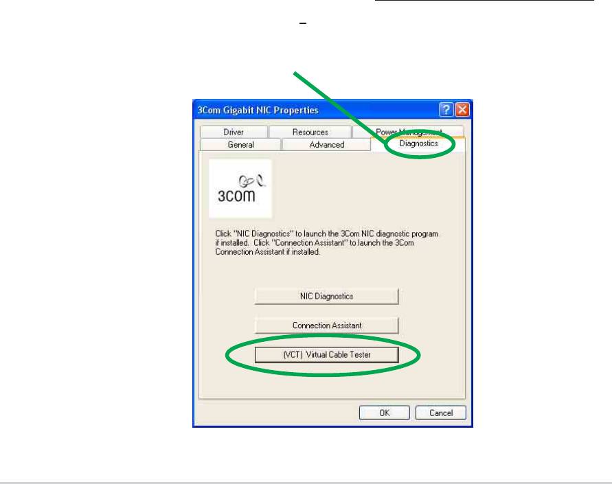
3. From the 3Com Gigabit LOM (3C940) Properties dialogue box,
select the Diagnostics tab.
5-26
Chapter 5: Software support
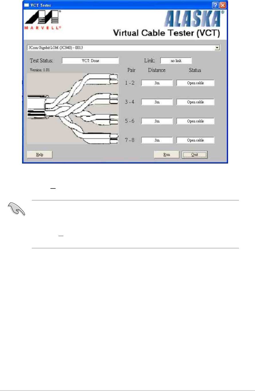
4. Click on the (VCT) Virtual Cable Tester button. The following
screen display appears.
5. Click on Run to execute test.
®
• The Virtual Cable Tester™ (VCT) feature is supported in Windows
®
XP™ and Windows
2000™ operating systems only.
• The Run button on the VCT Tester dialogue box is disabled if no
problem is detected on the network.
ASUS P4P800 motherboard user guide
5-27

5-28
Chapter 5: Software support
