Asus P4P800: Chapter 2
Chapter 2: Asus P4P800

Chapter 2
This chapter describes the hardware setup
procedures that you have to perform when
installing system components. It includes
details on the switches, jumpers, and
connectors on the motherboard.
Hardware information

Chapter summary
2.1 Motherboard installation ............................... 2-1
2.2 Motherboard layout ....................................... 2-2
2.3 Before you proceed ....................................... 2-3
2.4 Central Processing Unit (CPU) ..................... 2-4
2.5 System memory ........................................... 2-10
2.6 Expansion slots ........................................... 2-15
2.7 Jumpers ........................................................ 2-20
2.8 Connectors ................................................... 2-23
ASUS P4P800 motherboard
2.1 Motherboard installation
Before you install the motherboard, study the configuration of your chassis
to ensure that the motherboard fits into it. The P4P800 uses the ATX form
factor that measures 12 inches x 9.6 inches.
Make sure to unplug the power cord before installing or removing the
motherboard. Failure to do so may cause you physical injury and
damage motherboard components.
2.1.1 Placement direction
When installing the motherboard, make sure that you place it into the
chassis in the correct orientation. The edge with external ports goes to the
rear part of the chassis as indicated in the image below.
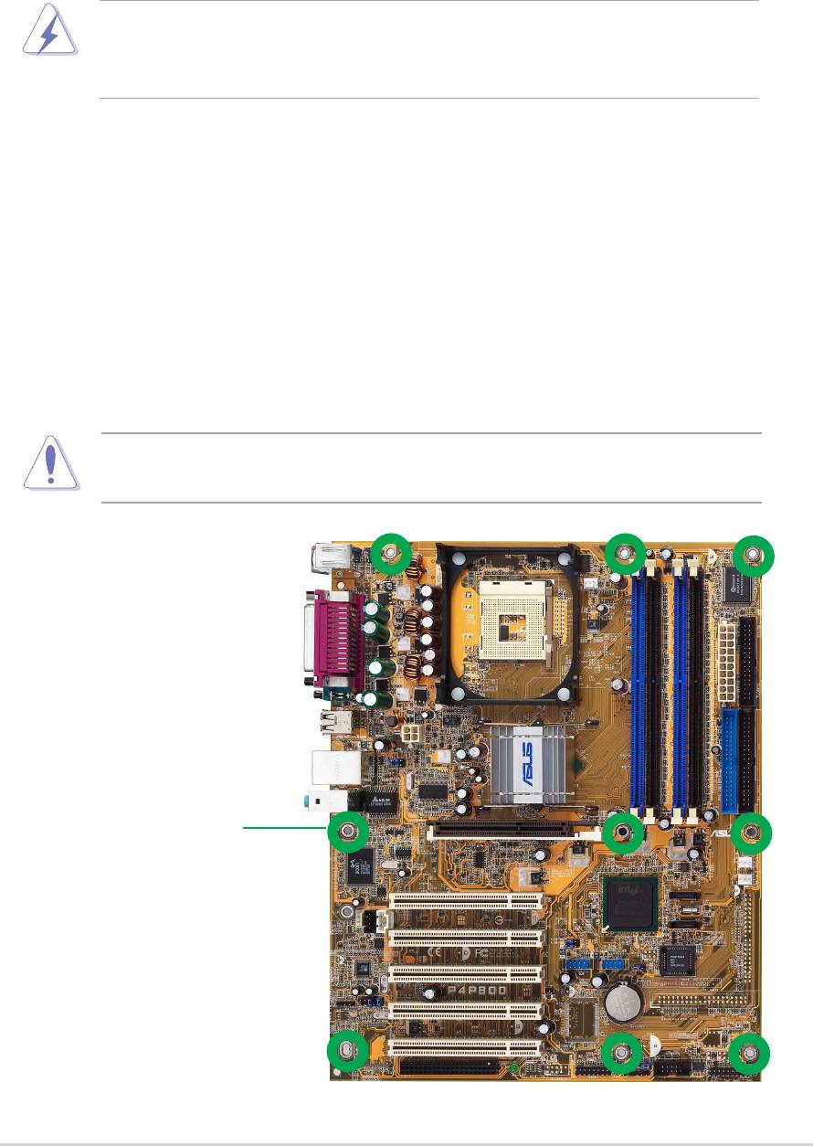
2.1.2 Screw holes
Place nine (9) screws into the holes indicated by circles to secure the
motherboard to the chassis.
Do not overtighten the screws! Doing so may damage the
motherboard.
Place this side towards
the rear of the chassis
ASUS P4P800 motherboard user guide
2-1
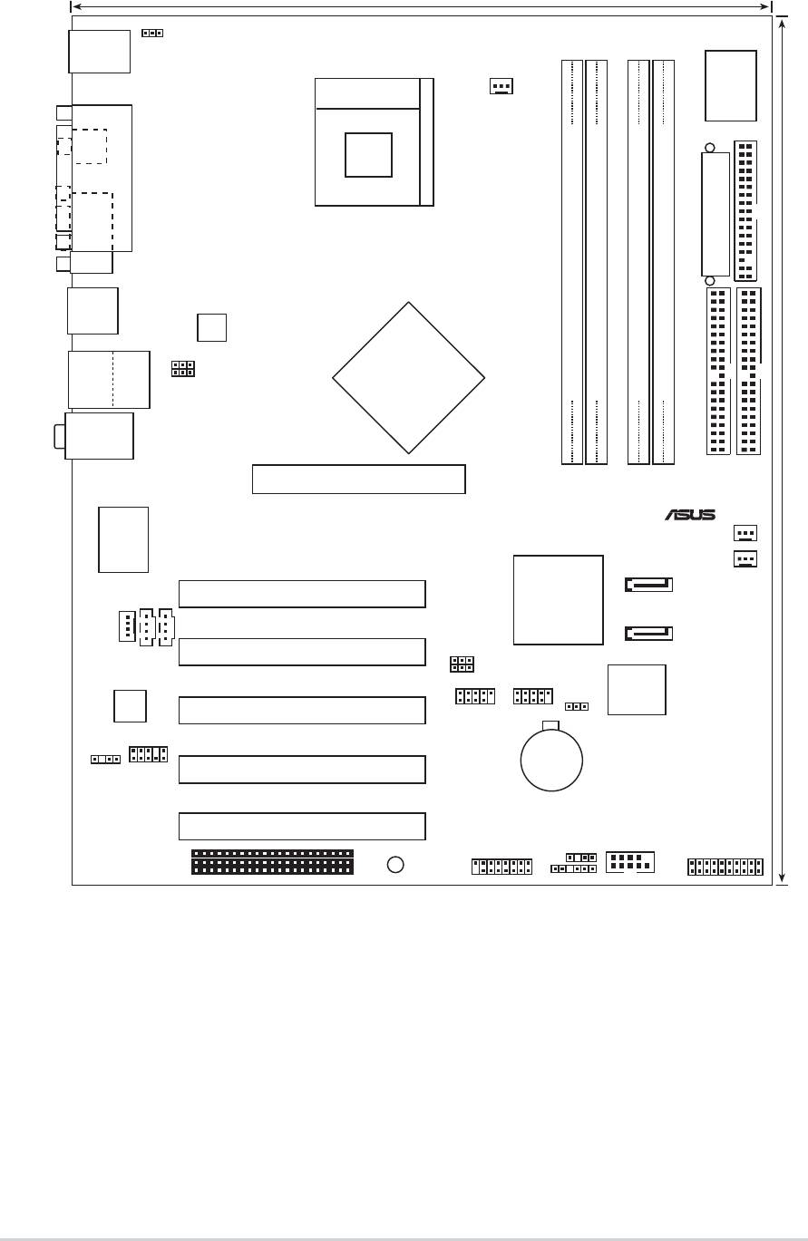
2.2 Motherboard layout
PCI1
P4P800
PANEL1
2-2
Chapter 2: Hardware information
®
PS/2KBMS
KBPWR
T: Mouse
B: Keyboard
Socket 478
I/O
CPU_FAN1
Super
SPDIF_O
PARALLEL PORT
COM1
ATX Power Connector
FLOPPY1
Intel
ATX12V1
82865PE
USB2.0
Top:
T: USB4
Memory
RJ-45
USBPW12
DDR DIMM_A1 (64 bit,184-pin module)
DDR DIMM_A2 (64 bit,184-pin module)
DDR DIMM_B1 (64 bit,184-pin module)
DDR DIMM_B2 (64 bit,184-pin module)
B: USB3
USBPW34
Controller
Hub
Top:Line In
Center:Line Out
Below:Mic In
Accelerated Graphics Port (AGP1)
PRI_IDE1
SEC_IDE1
CHA_FAN1
Gbit
3Com
3C940
PWR_FAN1
SATA1
Intel
CD1
ICH5R
SATA2
AUX1
MODEM1
PCI2
USBPW56
USBPW78
4Mbit
Firmware
Audio
CLRTC1
Hub
Codec
PCI3
USB_56 USB_78
FP_AUDIO
CR2032 3V
Lithium Cell
SPDIF_OUT
CMOS Power
PCI4
PCI5
SB_PWR1
CHASSIS1
COM2
GAME1
WIFI
24.5cm (9.6in)
USB20_12
30.5cm (12.0in)
SMB1
2.3 Before you proceed
Take note of the following precautions before you install motherboard
components or change any motherboard settings.
P4P800
ASUS P4P800 motherboard user guide
2-3
®
SB_PWR1
ON
OFF
Standby
Powere
Power
P4P800 Onboard LED
d
1. Unplug the power cord from the wall socket before touching any
component.
2. Use a grounded wrist strap or touch a safely grounded object or to
a metal object, such as the power supply case, before handling
components to avoid damaging them due to static electricity.
3. Hold components by the edges to avoid touching the ICs on them.
4. Whenever you uninstall any component, place it on a grounded
antistatic pad or in the bag that came with the component.
5. Before you install or remove any component, ensure that the
ATX power supply is switched off or the power cord is
detached from the power supply. Failure to do so may cause
severe damage to the motherboard, peripherals, and/or
components.
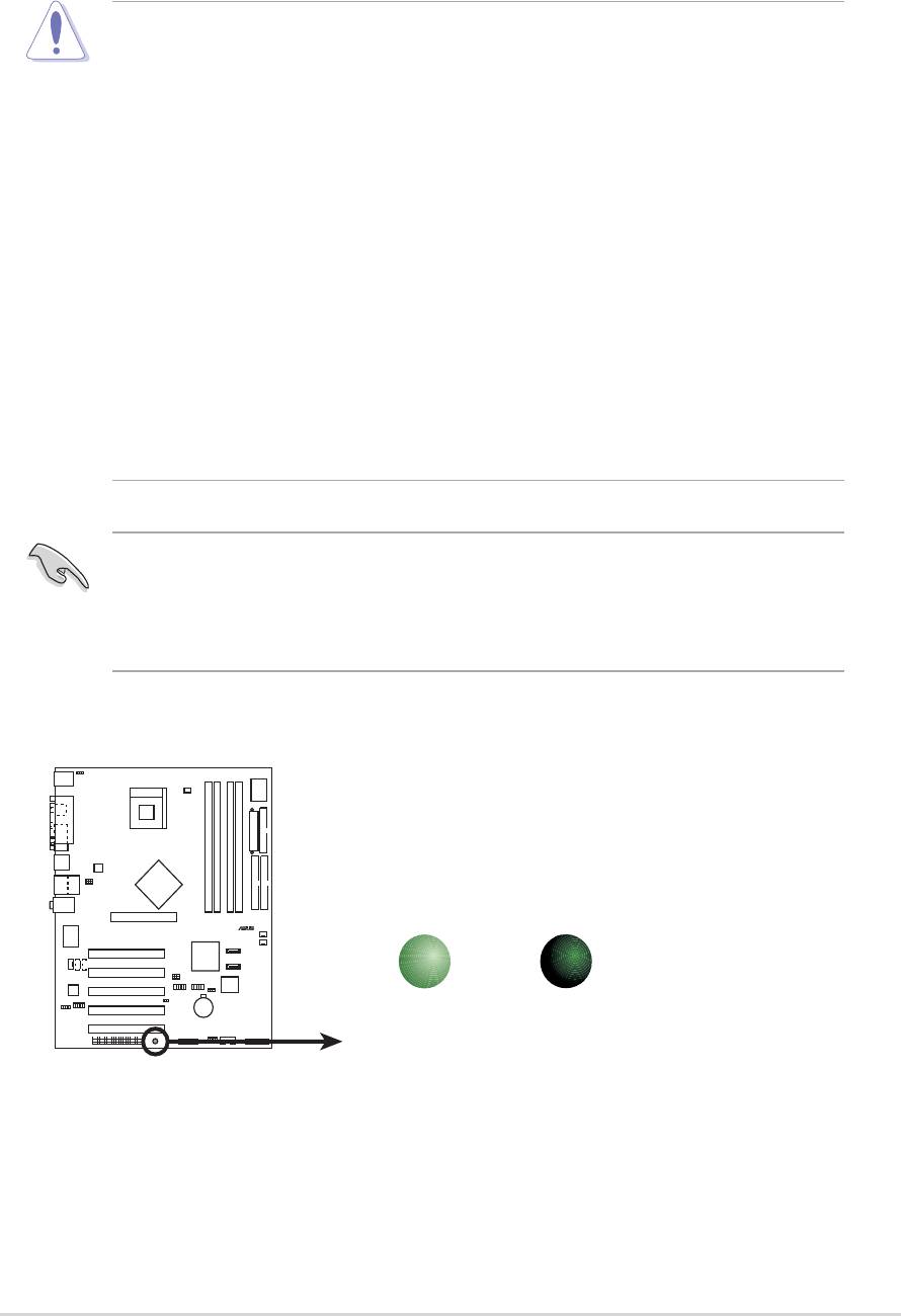
When lit, the green LED (SB_PWR) indicates that the system is ON, in
sleep mode, or in soft-off mode, a reminder that you should shut down
the system and unplug the power cable before removing or plugging in
any motherboard component.
Off
2.4 Central Processing Unit (CPU)
2.4.1 Overview
The motherboard comes with a surface mount 478-pin Zero Insertion
®
®
Force (ZIF) socket. The socket is designed for the Intel
Pentium
4
Processor in the 478-pin package with 512KB L2 cache on 0.13 micron
®
process. This processor includes the Intel
NetBurst™ micro-architecture
®
that features the rapid execution engine, Intel
Hyper-Threading
Technology, 800/533/400MHz system bus, and execution trace cache.
Together, these attributes improve system performance by allowing higher
core frequencies, faster execution of integer instructions, and data transfer
rates of 6.4GB/s, 4.2GB/s and 3.2GB/s.
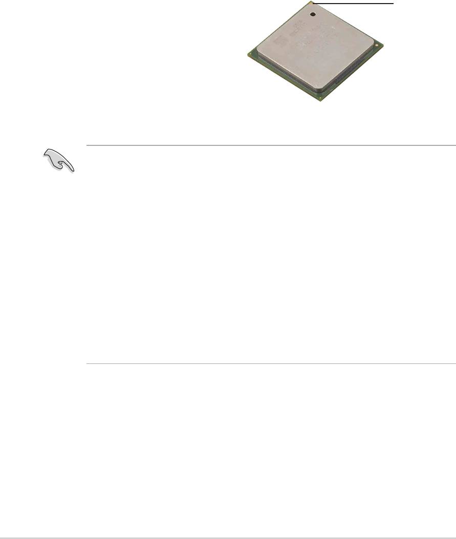
Gold Mark
Note in the illustration that the CPU
has a gold triangular mark on one
corner. This mark indicates the
processor Pin 1 that should match a
specific corner of the CPU socket.
®
Notes on Intel
Hyper-Threading Technology
1. This motherboard supports Intel Pentium 4 CPUs with Hyper-
Threading Technology.
2. Hyper-Threading Technology is supported under Windows XP and
Linux 2.4.x (kernel) and later versions only. Under Linux, use the
Hyper-Threading compliler to compile the code. If you are using any
other operating systems, disable the Hyper-Threading Techonology
item in BIOS to ensure system stability and performance.
3. It is recommended that you install WinXP Service Pack 1.
4. Make sure to enable the Hyper-Threading Technology item in BIOS
before installing a supported operating system.
5. For more information on Hyper-Threading Technology, visit
www.intel.com/info/hyperthreading.
To use the Hyper-Threading Technology on this motherboard:
1. Buy an Intel Pentium 4 CPU that supports Hyper-Threading
Technology. Install the CPU.
2. Power up the system and enter BIOS Setup (see Chapter 2). Under
the Advanced Menu, make sure that the item CPU Configuration->
Hyper-Threading Technology is set to Enabled. The item appears
only if you installed a CPU that supports Hyper-Threading Technology.
3. Reboot the computer.
2-4
Chapter 2: Hardware information
2.4.2 Installing the CPU
Follow these steps to install a CPU.
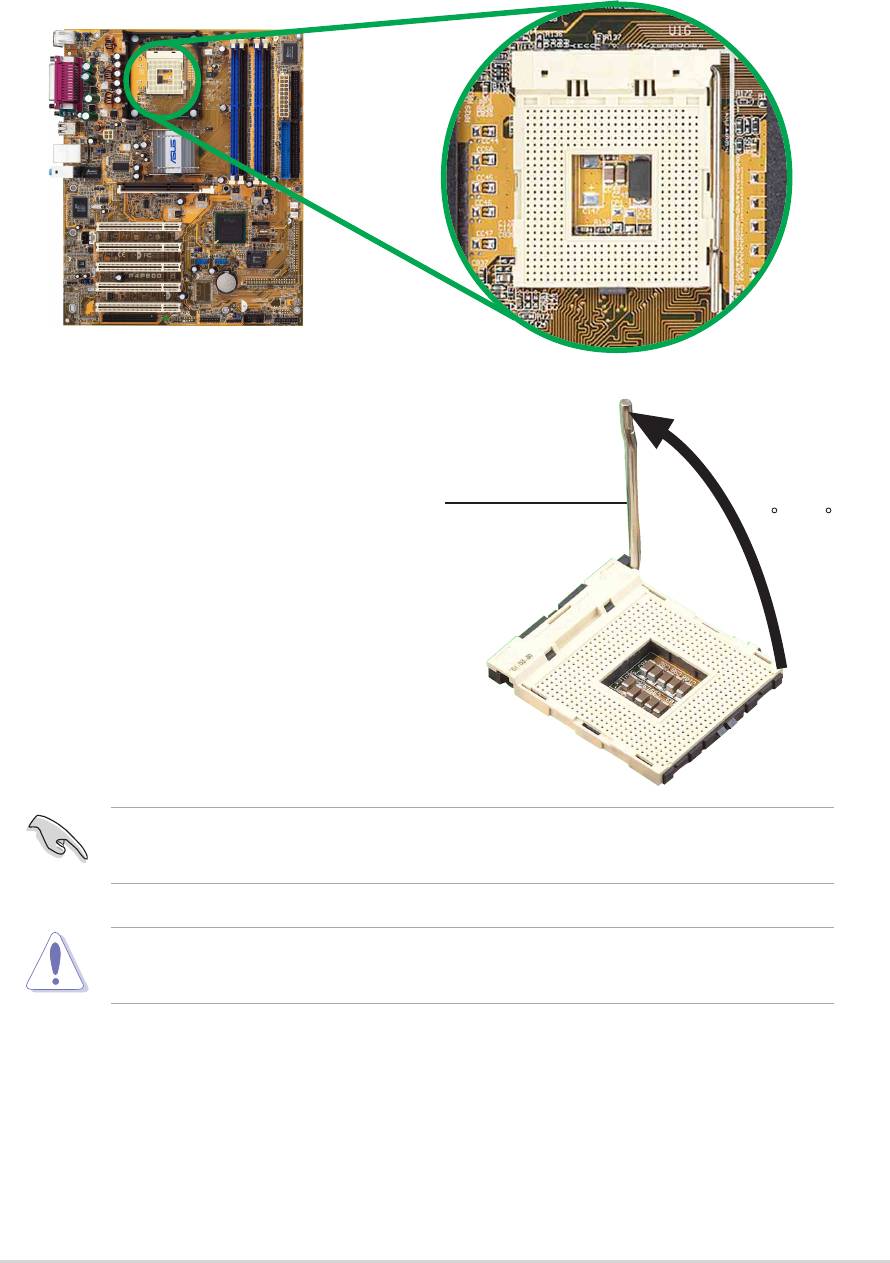
1. Locate the 478-pin ZIF socket on the motherboard.
2. Unlock the socket by pressing the
lever sideways, then lift it up to a
90°-100° angle.
Socket Lever
90 -10
ASUS P4P800 motherboard user guide
2-5
0
Make sure that the socket lever is lifted up to 90°-100° angle,
otherwise the CPU does not fit in completely.
Incorrect installation of the CPU into the socket may bend the pins and
severely damage the CPU!
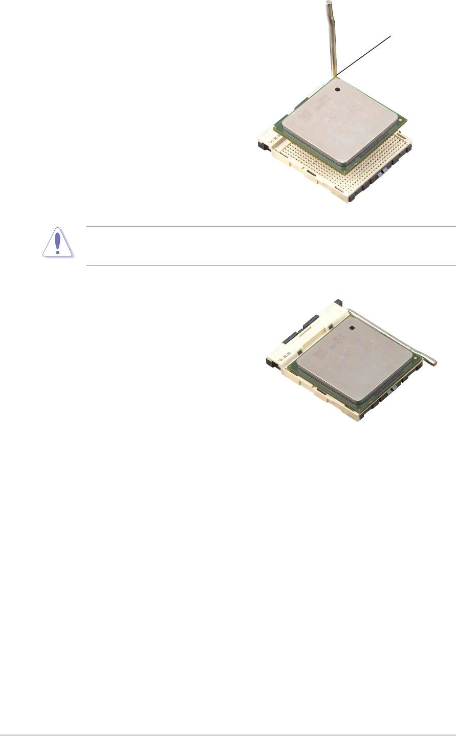
3. Position the CPU above the
Gold Mark
socket such that its marked
corner matches the base of the
socket lever.
4. Carefully insert the CPU into the
socket until it fits in place.
The CPU fits only in one correct orientation. DO NOT force the CPU
into the socket to prevent bending the pins and damaging the CPU!
5. When the CPU is in place, push
down the socket lever to secure
the CPU. The lever clicks on the
side tab to indicate that it is
locked.
2-6
Chapter 2: Hardware information
2.4.3 Installing the heatsink and fan
®
®
The Intel
Pentium
4 Processor requires a specially designed heatsink
and fan assembly to ensure optimum thermal condition and performance.
When you buy a boxed Intel Pentium 4 Processor, the package
includes the heatsink, fan, and retention mechanism.
In case you buy a CPU separately, make sure that you use only Intel
certified heatsink and fan.
Follow these steps to install the CPU heatsink and fan.
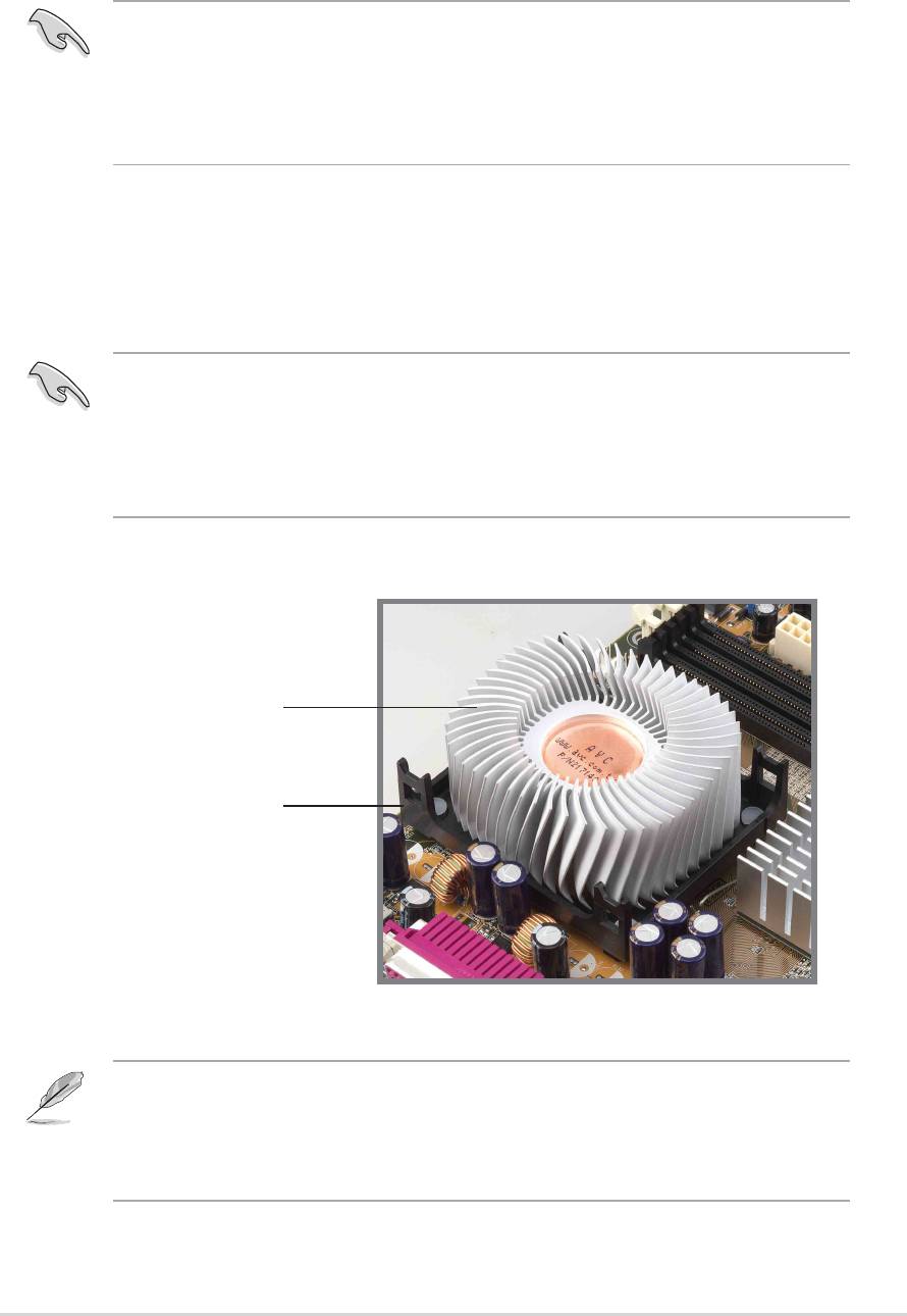
1. Place the heatsink on top of the installed CPU, making sure that the
heatsink fits properly on the retention module base.
The retention module base is already installed on the motherboard
upon purchase.
You do not have to remove the retention module base when installing
the CPU or installing other motherboard components.
CPU Heatsink
Retention Module Base
Your boxed Intel Pentium 4 Processor package should come with
installation instructions for the CPU, heatsink, and the retention
mechanism. If the instructions in this section do not match the CPU
documentation, follow the latter.
ASUS P4P800 motherboard user guide
2-7
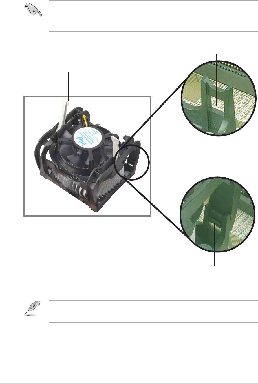
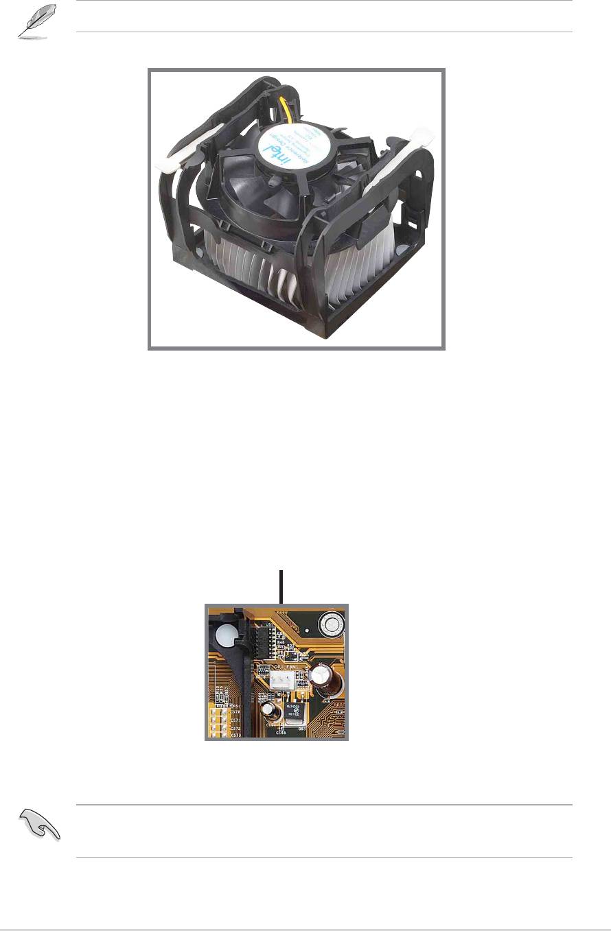
2. Position the fan with the retention mechanism on top of the heatsink.
Align and snap the four hooks of the retention mechanism to the holes
on each corner of the module base.
Make sure that the fan and retention mechanism assembly perfectly
fits the heatsink and module base, otherwise you cannot snap the
hooks into the holes.
Retention Hole
Retention Lock
Retention Hook Snapped
to the Retention Hole
Keep the retention locks lifted upward while fitting the retention
mechanism to the module base.
2-8
Chapter 2: Hardware information
3. Push down the locks on the retention mechanism to secure the
heatsink and fan to the module base.
When secure, the retention locks should point to opposite directions.
2.4.4 Connecting the CPU fan cable
When the fan, heatsink, and the retention mechanism are in place,
connect the CPU fan cable to the connector on the motherboard labeled
CPU_FAN.
CPU Fan Connector
(CPU_FAN)
Don’t forget to connect the CPU fan connector! Hardware monitoring
errors may occur if you fail to plug this connector.
ASUS P4P800 motherboard user guide
2-9
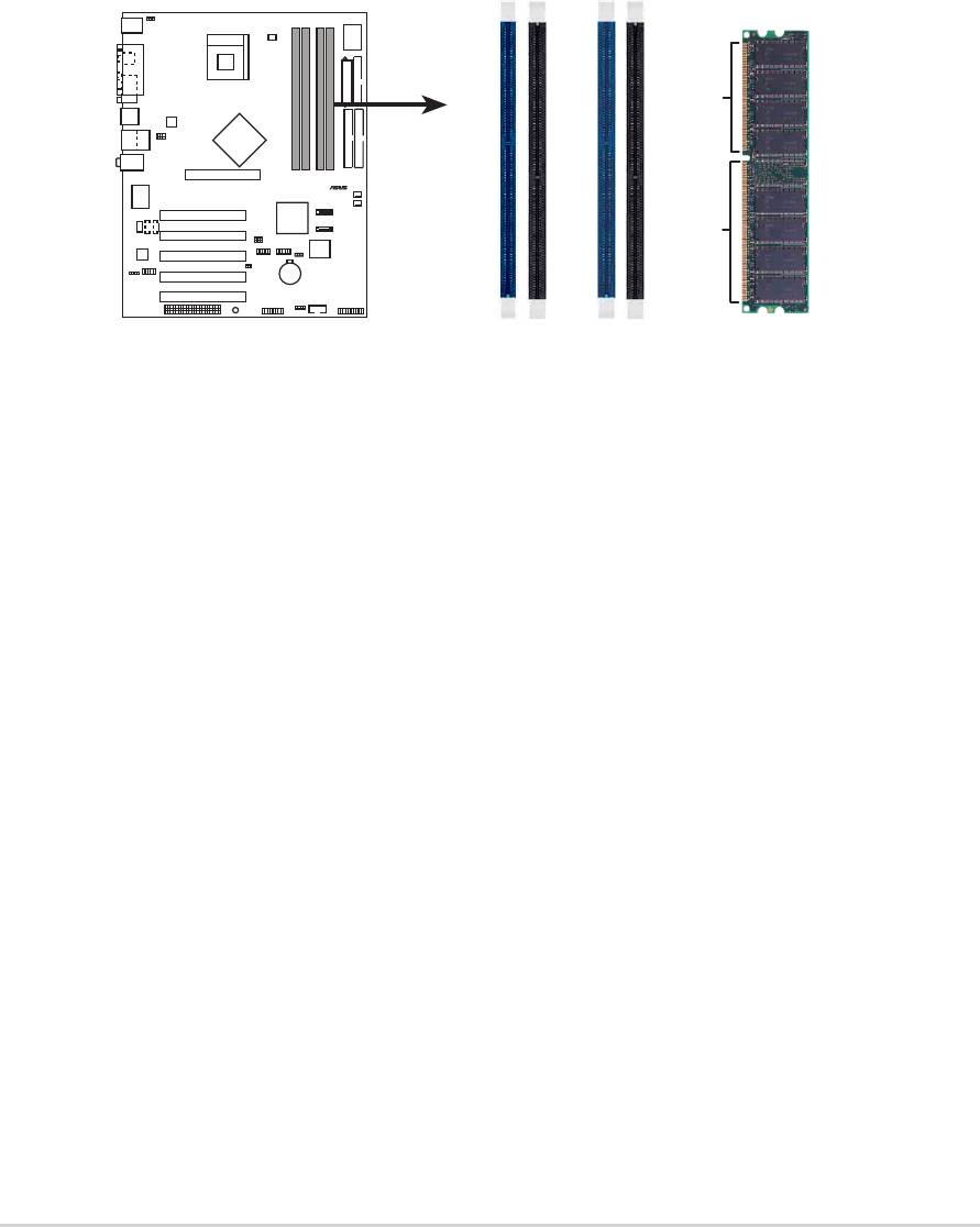
2.5 System memory
2.5.1 Overview
The motherboard comes with four Double Data Rate (DDR) Dual Inline
Memory Module (DIMM) sockets. These sockets support up to 4GB
system memory using 184-pin unbuffered non-ECC PC3200/2700/PC2100
DDR DIMMs and allow up to 6.4 GB/s data transfer rate.
The following figure illustrates the location of the DDR DIMM sockets.
P4P800
Notes on DDR technology
The DDR SDRAM technology evolved from the mainstream PC66, PC100,
PC133 memory known as Single Data Rate (SDR) SDRAM. DDR memory
however, has the ability to perform two data operations in one clock cycle,
thus providing twice the throughput of SDR memory.
A DDR DIMM has the same physical dimensions as an SDR DIMM, but it
has a 184-pin footprint compared to the 168-pin of the SDR DIMM. Also, a
DDR DIMM is single notched while an SDR DIMM is double notched.
Therefore, a DDR DIMM is not backward compatible with SDR, and should
be installed only in a socket specially designed for DDR DIMMs.
2-10
Chapter 2: Hardware information
®
DIMM_A
80 Pins104 Pins
P4P800 184-Pin DDR DIMM Sockets
1
DIMM_A
2
DIMM_B
1
DIMM_B
2

2.5.2 Memory configurations
You may install 64MB, 128MB, 256MB, 512MB, and 1GB DDR DIMMs into
the DIMM sockets using the memory configurations in this section.
Important notes on memory configurations
1. Installing DDR DIMMs other than the recommended configurations
may cause memory sizing error or system boot failure. Use any of
the recommended configurations in Table 1.
2. In dual-channel configurations, install only identical (the same
type and size) DDR DIMM pairs for each channel.
3. Always install DIMMs with the same CAS latency. For optimum
compatibility, it is recommended that you obtain memory modules
from the same vendor. See list of qualified vendors on page 2-13.
4. Make sure that the memory frequency matches the CPU FSB
(Front Side Bus). Refer to Table 2.
5. DIMMs installed into any three sockets will function in single-
channel mode.
6. When all four sockets are populated with 1GB DIMMs (total 4GB),
the system may detect only 3+GB (a little less than 4GB) due to
ICH5R resource allocation.
7. Double-sided DDR DIMMs with X16 (databus width = 16-bit)
memory chips are not supported due to chipset limitation.
8. It is recommended to use the blue DIMM slots first.
ASUS P4P800 motherboard user guide
2-11

Table 1 Recommended memory configurations
Sockets
Mode DIMM_A1 DIMM_A2 DIMM_B1 DIMM_B2
Single-channel (1) Populated — — —
(2) — Populated — —
(3) — — Populated —
(4) — — — Populated
Dual-channel* (1) Populated
— Populated —
(2) —
Populated — Populated
(3) Populated Populated Populated Populated
* Use only identical DDR DIMM pairs.
* For dual-channel configuration (3), you may:
• install identical DIMMs in all four sockets
or
• install identical DIMM pair in DIMM_A1 and DIMM_B1 (blue sockets)
and identical DIMM pair in DIMM_A2 and DIMM_B2 (black sockets)
Table 2 Memory frequency/CPU FSB synchronization
CPU FSB DDR DIMM Type Memory Frequency
800 MHz PC3200/PC2700*/PC2100 400/333*/266 MHz
533 MHz PC2700/PC2100 333/266 MHz
400 MHz PC2100 266 MHz
• *When using 800MHz CPU FSB, PC2700 DDR DIMMs may run
only at 320MHz (not 333MHz) due to chipset limitation.
• The following FSB/DDR ratios are not supported: 400/333,
400/400, 533/400.
• FSB/DDR setting 800/333 is recognized as FSB/DDR 800/320.
2-12
Chapter 2: Hardware information

2.5.2.2 DDR Qualified Vendor List
The following table lists the PC3200 (DDR400) memory modules that have
been tested and qualified for use with this motherboard.
Size Vendor Model Brand SS/DS Component A* B* C*
256MB A DATA MDGA5F3G315B1EC2 ADATA SS ADD8608A8A-5B • • •
256MB A DATA MDOWB5F3G316B1EAE Winbond SS W942508BH-5 • •
256MB A DATA MDOSS6F3G31JB1EAE SAMSUNG SS K4H560838D-TCC4 • •
256MB Apacer 77.10636.465 SAMSUNG SS K4H560838D-TCC4 • • •
512MB Apacer 77.10736.464 SAMSUNG DS K4H560838D-TCC4 • • •
256MB Corsair CMX256-3500C2 XMS3502v1.1 N/A SS N/A • •
512MB Corsair CMX512-3500C2 XMS3502v1.1 N/A DS N/A • •
256MB Hynix HYMD232646B8J-D43AA Hynix SS HY5DU56822BT-D43 • • •
512MB Hynix HYMD232646B8J-D43AA Hynix DS HY5DU56822BT-D43 • • •
128MB Infineon HYS64D16301GU-5-B Infineon SS HYB25D256160BT-5B • • •
256MB Infineon HYS64D32300GU-5-B Infineon SS HYB25D256800BT-5B • • •
512MB Infineon HYS64D64320GU-5-B Infineon SS HYB25D256800BT-5B • • •
256MB Kingston KVR400X64C25/256 Winbond SS W942508BH-5 • • •
512MB Kingston KVR400X64C25/512 Winbond DS W942508BH-5 •
256MB Kingston KHX3500/256 N/A SS N/A • •
256MB MICRON MT16VDDT3264AG-403B2 MICRON DS MT46V16M8-5TESB • •
512MB PSC AL6D8A53TK1-5B PSC DS A2S56D30ATP • • •
256MB SAMSUNG M368L3223ETM-CCC SAMSUNG SS K4H560838E-TCCC • • •
512MB SAMSUNG M368L6423ETM-CCC SAMSUNG DS K4H560838E-TCCC • • •
256MB Transcend TS32MLD64V4F3 SAMSUNG SS K4H560838D-TCC4 • •
256MB Transcend TS32MLD64V4F3 Mosel SS V58C2256804SAT5 • •
512MB Transcend TS64MLD64V4F3 SAMSUNG DS K4H560838D-TCC4 • •
256MB Transcend TS64MLD64V4F3 Mosel DS V58C2256804SAT5 • • •
256MB TwinMOS M2G9108AFATT9FD81AA4T TwinMOS SS TMD7608F8E50D • • •
512MB TwinMOS M2G9J16AGATT9F081AA4T TwinMOS DS TMD7608F8E50D • •
256MB TwinMOS M2S9108AFAPS9F0811A-T PSC SS A2S56D30ATP • • •
256MB Winbond W9425GCDB-5 Winbond SS W942508CH-5 • • •
512MB Winbond W9451GCDB-5 Winbond DS W942508CH-5 • • •
A* - supports one module inserted in any slot in a Single-channel memory
configuration.
B* - supports one pair of modules inserted into either the blue slots or the black
slots as one pair of Dual-channel memory configuration .
C* - support for 4 modules inserted into the blue and black slots as two pairs of
Dual-channel memory configuration.
Obtain DDR DIMMs only from ASUS qualified vendors for better
system performance.
Make sure to use only the tested and qualified DDR400 DIMMs listed
above. Other DDR DIMMs manufactured by other vendors may not be
suitable for this motherboard. Visit the ASUS website (www.asus.com)
for the latest qualified vendor DDR 400 module list.
ASUS P4P800 motherboard user guide
2-13
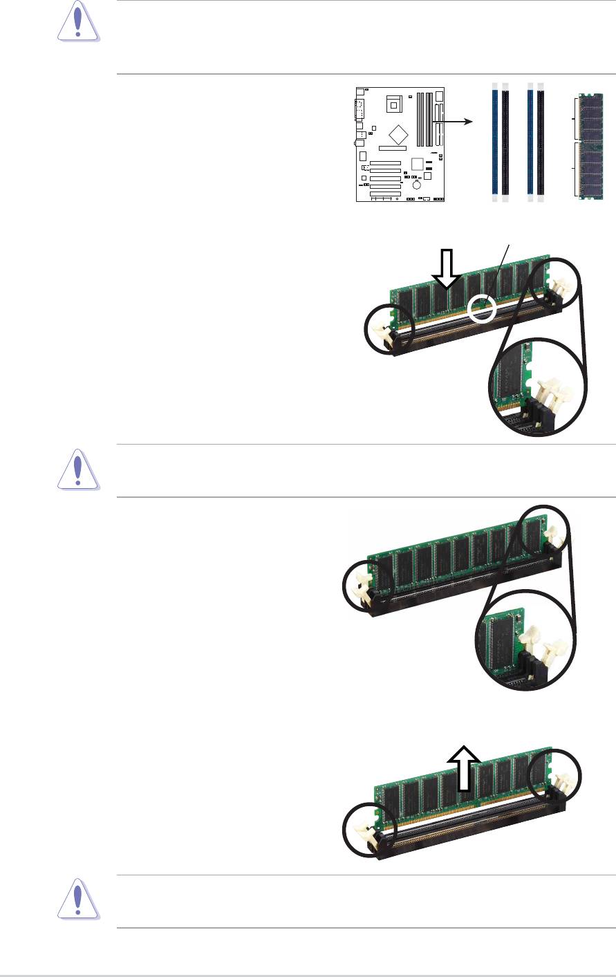
2.5.3 Installing a DIMM
Follow these steps to install a DIMM.
1. Locate the DIMM sockets in the
motherboard.
P4P800
2. Unlock a DIMM socket by
pressing the retaining clips
outward.
3. Align a DIMM on the socket such
that the notch on the DIMM
matches the break on the socket.
4. Firmly insert the DIMM into the
socket until the retaining clips
snap back in place and the DIMM
is properly seated.
2.5.4 Removing a DIMM
Follow these steps to remove a DIMM.
1. Simultaneously press the
retaining clips outward to unlock
the DIMM.
2. Remove the DIMM from the socket.
2-14
Chapter 2: Hardware information
®
DIMM_A
80 Pins104 Pins
P4P800 184-Pin DDR DIMM Sockets
1
DIMM_A
2
DIMM_B
1
DIMM_B
2
Make sure to unplug the power supply before adding or removing
DIMMs or other system components. Failure to do so may cause
severe damage to both the motherboard and the components.
DDR DIMM
Unlocked Retaining Clip
A DDR DIMM is keyed with a notch so that it fits in only one direction.
DO NOT force a DIMM into a socket to avoid damaging the DIMM.
Locked Retaining Clip
Support the DIMM lightly with your fingers when pressing the retaining
clips. The DIMM might get damaged when it flips out with extra force.

2.6 Expansion slots
In the future, you may need to install expansion cards. The motherboard
has five PCI slots and one Accelerated Graphics Port (AGP) slot. The
following sub-sections describe the slots and the expansion cards that
they support.
Make sure to unplug the power cord before adding or removing
expansion cards. Failure to do so may cause you physical injury and
damage motherboard components.
2.6.1 Installing an expansion card
Follow these steps to install an expansion card.
1. Before installing the expansion card, read the documentation that
came with it and make the necessary hardware settings for the card.
2. Remove the system unit cover (if your motherboard is already installed
in a chassis).
3. Remove the bracket opposite the slot that you intend to use. Keep the
screw for later use.
4. Align the card connector with the slot and press firmly until the card is
completely seated on the slot.
5. Secure the card to the chassis with the screw you removed earlier.
6. Replace the system cover.
2.6.2 Configuring an expansion card
After installing the expansion card, configure the card by adjusting the
software settings.
1. Turn on the system and change the necessary BIOS settings, if any.
See Chapter 4 for information on BIOS setup.
2. Assign an IRQ to the card. Refer to the tables on the next page.
3. Install the software drivers for the expansion card.
ASUS P4P800 motherboard user guide
2-15

Standard Interrupt Assignments
IRQ Priority Standard Function
0 1 System Timer
1 2 Keyboard Controller
2 N/A Programmable Interrupt
3* 11 Communications Port (COM2)
4* 12 Communications Port (COM1)
5* 13 Sound Card (sometimes LPT2)
6 14 Floppy Disk Controller
7* 15 Printer Port (LPT1)
8 3 System CMOS/Real Time Clock
9* 4 ACPI Mode when used
10* 5 IRQ Holder for PCI Steering
11* 6 IRQ Holder for PCI Steering
12* 7 PS/2 Compatible Mouse Port
13 8 Numeric Data Processor
14* 9 Primary IDE Channel
15* 10 Secondary IDE Channel
* These IRQs are usually available for ISA or PCI devices.
IRQ assignments for this motherboard
ABCDEFGH
PCI slot 1 — — — — — shared — —
PCI slot 2 — — — — — — shared —
PCI slot 3 — — — — — — — shared
PCI slot 4 — — — — shared — — —
PCI slot 5 — — — — — shared — —
AGP slot used — — — — — — —
Onboard USB 1.1/2.0 controller — — — — shared shared shared shared
Onboard LAN — — — — — — shared —
Onboard Audio — — used — — — — —
When using PCI cards on shared slots, ensure that the drivers support
“Share IRQ” or that the cards do not need IRQ assignments.
Otherwise, conflicts will arise between the two PCI groups, making the
system unstable and the card inoperable.
2-16
Chapter 2: Hardware information

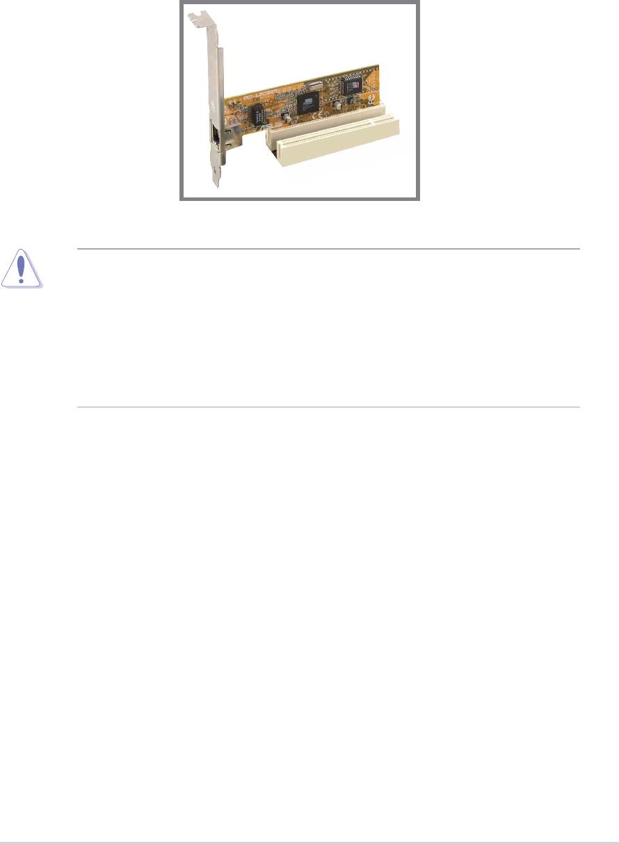
2.6.3 PCI slots
There are five 32-bit PCI slots on this motherboard. The slots support PCI
cards such as a LAN card, SCSI card, USB card, and other cards that
comply with PCI specifications. The following figure shows a LAN card
installed on a PCI slot.
• The PCI 5 slot and the WiFi slot can not be used at the same time.
• When installing long PCI cards, it is recommended that to install in
PCI slots 2, 4 or 5. Long PCI cards installed in PCI slot 1 may
interfere with the SATA connectors.
• When installing 64-bit PCI cards, it is recommended not to install in
PCI slot 3. 64-bit PCI cards installed in PCI slot 3 may interfere
with the USB connectors.
ASUS P4P800 motherboard user guide
2-17
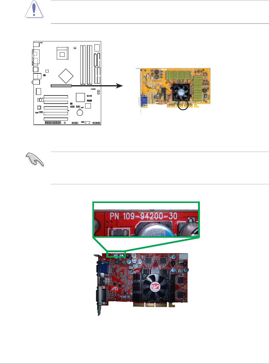
2.6.4 AGP slot
This motherboard has an Accelerated Graphics Port (AGP) slot that only
supports +1.5V AGP cards. When you buy an AGP card, make sure that
you ask for one with +1.5V specification. Note the notches on the card
golden fingers to ensure that they fit the AGP slot on your motherboard.
P4P800
2-18
Chapter 2: Hardware information
®
Install only 1.5V AGP cards on this motherboard! 3.3V AGP cards are
not supported in this motherboard.
Keyed for 1.5v
P4P800 Accelerated Graphics Port (AGP)
If installing the ATi 9500 or 9700 Pro Series VGA cards, use only the
card version PN xxx-xxxxx-30 or later, for optimum performance and
overclocking stability.
2.6.5 Wi-Fi slot
The Wi-Fi (Wireless Fidelity) slot will support the ASUS Wi-Fi module
when available. Visit the ASUS website (www.asus.com) for product
updates.
The Wi-Fi slot conforms to the Institute of Electrical and Electronics
Engineers (IEEE) 802.11b standard for wireless devices operating in the
2.4 GHz frequency band. This standard includes provisions for three radio
technologies: direct sequence spread spectrum, frequency hopping
spread spectrum, and infrared. Devices that comply with the 802.11b
standard operate at data rates of up to 11 Mbps for direct sequence
spread spectrum.
The IEEE 802.11b specification allocates the 2.4 GHz frequency band into
14 overlapping operating channels. Each Channel corresponds to a
different set of frequencies. If operating multiple 802.11b wireless PCI
cards in the same vicinity, the distance between the center frequencies
must be at least 25 MHz to avoid interference.
The channels available to an 802.11b wireless PCI card will vary from
country to country. In the United States, the 802.11b standard allocates 11
operating channels for direct sequence devices. Channels 1, 6, and 11 are
independent and do not overlap with each other.
P4P800
The PCI 5 slot and the Wi-Fi slot may not be used at the same time.
ASUS P4P800 motherboard user guide
2-19
®
WIF
P4P800 WIRELESS Connectors
I
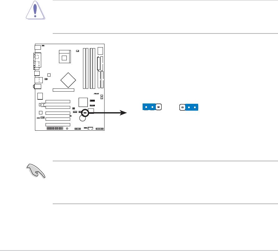
2.7 Jumpers
1. Clear RTC RAM (CLRTC1)
This jumper allows you to clear the Real Time Clock (RTC) RAM in
CMOS. You can clear the CMOS memory of date, time, and system
setup parameters by erasing the CMOS RTC RAM data. The RAM
data in CMOS, that include system setup information such as system
passwords, is powered by the onboard button cell battery.
To erase the RTC RAM:
1. Turn OFF the computer and unplug the power cord.
2. Remove the onboard battery.
3. Move the jumper cap from pins 1-2 (default) to pins 2-3. Keep the
cap on pins 2-3 for about 5~10 seconds, then move the cap back
to pins 1-2.
4. Replace the battery.
5. Plug the power cord and turn ON the computer.
6. Hold down the <Del> key during the boot process and enter BIOS
setup to re-enter data.
P4P800
2-20
Chapter 2: Hardware information
®
Except when clearing the RTC RAM, never remove the cap on
CLRTC1 jumper default position. Removing the cap will cause system
boot failure!
CLRTC1
12 23
Normal Clear CMOS
(Default)
P4P800 Clear RTC RAM
You do not need to clear the RTC when the system hangs due to
overclocking. For system failure due to overclocking, use the C.P.R.
(CPU Parameter Recall) feature. Shut down and reboot the system so
BIOS can automatically reset parameter settings to default values.

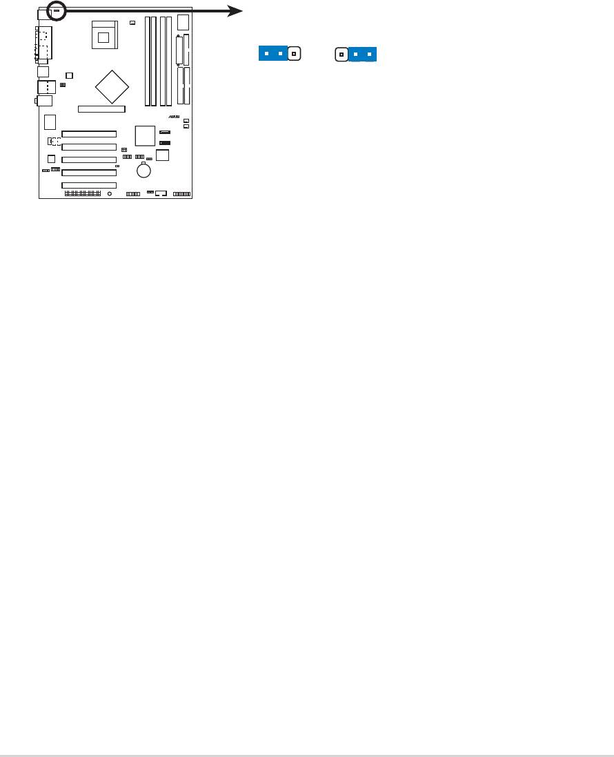
2. Keyboard power (3-pin KBPWR)
This jumper allows you to enable or disable the keyboard wake-up
feature. Set this jumper to pins 2-3 (+5VSB) if you wish to wake up the
computer when you press a key on the keyboard (the default value is
[Disabled]). This feature requires an ATX power supply that can supply
at least 1A on the +5VSB lead and a corresponding setting in the
BIOS. (see section 4.5.1 Power Up Control)
P4P800
ASUS P4P800 motherboard user guide
2-21
®
KBPWR
2312
+5V +5VSB
(Default)
P4P800 Keyboard Power Setting
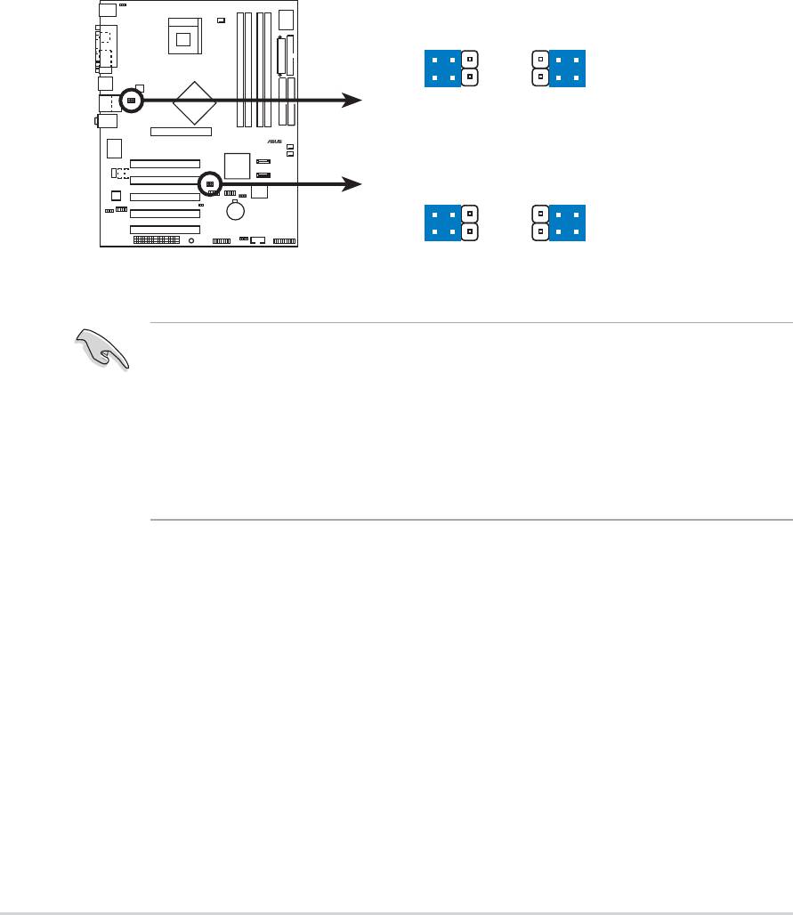
3. USB device wake-up (3-pin USBPW12, USBPW34, USBPW56,
USBPW78)
Set these jumpers to +5V to wake up the computer from S1 sleep
mode (CPU stopped, DRAM refreshed, system running in low power
mode) using the connected USB devices. Set to +5VSB to wake up
from S3 and S4 sleep modes (no power to CPU, DRAM in slow
refresh, power supply in reduced power mode).
The USBPW12 and USBPW34 jumpers are for the rear USB ports.
The USBPW56 and USBPW78 jumpers are for the internal USB
header that you can connect to the front USB ports.
P4P800
2-22
Chapter 2: Hardware information
®
P4P800 USB Device Wake Up
3
21
2
+5V
+5VS
(Default)
USBPW12
B
USBPW34
3
21
2
+5V
+5VS
(Default)
B
USBPW56
USBPW78
1. The USB device wake-up feature requires a power supply that can
provide 500mA on the +5VSB lead for each USB port. Otherwise,
the system would not power up.
2. The total current consumed must NOT exceed the power supply
capability (+5VSB) whether under normal condition or in sleep
mode.

2.6 Expansion slots
In the future, you may need to install expansion cards. The motherboard
has five PCI slots and one Accelerated Graphics Port (AGP) slot. The
following sub-sections describe the slots and the expansion cards that
they support.
Make sure to unplug the power cord before adding or removing
expansion cards. Failure to do so may cause you physical injury and
damage motherboard components.
2.6.1 Installing an expansion card
Follow these steps to install an expansion card.
1. Before installing the expansion card, read the documentation that
came with it and make the necessary hardware settings for the card.
2. Remove the system unit cover (if your motherboard is already installed
in a chassis).
3. Remove the bracket opposite the slot that you intend to use. Keep the
screw for later use.
4. Align the card connector with the slot and press firmly until the card is
completely seated on the slot.
5. Secure the card to the chassis with the screw you removed earlier.
6. Replace the system cover.
2.6.2 Configuring an expansion card
After installing the expansion card, configure the card by adjusting the
software settings.
1. Turn on the system and change the necessary BIOS settings, if any.
See Chapter 4 for information on BIOS setup.
2. Assign an IRQ to the card. Refer to the tables on the next page.
3. Install the software drivers for the expansion card.
ASUS P4P800 motherboard user guide
2-15

Standard Interrupt Assignments
IRQ Priority Standard Function
0 1 System Timer
1 2 Keyboard Controller
2 N/A Programmable Interrupt
3* 11 Communications Port (COM2)
4* 12 Communications Port (COM1)
5* 13 Sound Card (sometimes LPT2)
6 14 Floppy Disk Controller
7* 15 Printer Port (LPT1)
8 3 System CMOS/Real Time Clock
9* 4 ACPI Mode when used
10* 5 IRQ Holder for PCI Steering
11* 6 IRQ Holder for PCI Steering
12* 7 PS/2 Compatible Mouse Port
13 8 Numeric Data Processor
14* 9 Primary IDE Channel
15* 10 Secondary IDE Channel
* These IRQs are usually available for ISA or PCI devices.
IRQ assignments for this motherboard
ABCDEFGH
PCI slot 1 — — — — — shared — —
PCI slot 2 — — — — — — shared —
PCI slot 3 — — — — — — — shared
PCI slot 4 — — — — shared — — —
PCI slot 5 — — — — — shared — —
AGP slot used — — — — — — —
Onboard USB 1.1/2.0 controller — — — — shared shared shared shared
Onboard LAN — — — — — — shared —
Onboard Audio — — used — — — — —
When using PCI cards on shared slots, ensure that the drivers support
“Share IRQ” or that the cards do not need IRQ assignments.
Otherwise, conflicts will arise between the two PCI groups, making the
system unstable and the card inoperable.
2-16
Chapter 2: Hardware information
2.6.3 PCI slots
There are five 32-bit PCI slots on this motherboard. The slots support PCI
cards such as a LAN card, SCSI card, USB card, and other cards that
comply with PCI specifications. The following figure shows a LAN card
installed on a PCI slot.
• The PCI 5 slot and the WiFi slot can not be used at the same time.
• When installing long PCI cards, it is recommended that to install in
PCI slots 2, 4 or 5. Long PCI cards installed in PCI slot 1 may
interfere with the SATA connectors.
• When installing 64-bit PCI cards, it is recommended not to install in
PCI slot 3. 64-bit PCI cards installed in PCI slot 3 may interfere
with the USB connectors.
ASUS P4P800 motherboard user guide
2-17

2.6.4 AGP slot
This motherboard has an Accelerated Graphics Port (AGP) slot that only
supports +1.5V AGP cards. When you buy an AGP card, make sure that
you ask for one with +1.5V specification. Note the notches on the card
golden fingers to ensure that they fit the AGP slot on your motherboard.
P4P800
2-18
Chapter 2: Hardware information
®
Install only 1.5V AGP cards on this motherboard! 3.3V AGP cards are
not supported in this motherboard.
Keyed for 1.5v
P4P800 Accelerated Graphics Port (AGP)
If installing the ATi 9500 or 9700 Pro Series VGA cards, use only the
card version PN xxx-xxxxx-30 or later, for optimum performance and
overclocking stability.

2.6.5 Wi-Fi slot
The Wi-Fi (Wireless Fidelity) slot will support the ASUS Wi-Fi module
when available. Visit the ASUS website (www.asus.com) for product
updates.
The Wi-Fi slot conforms to the Institute of Electrical and Electronics
Engineers (IEEE) 802.11b standard for wireless devices operating in the
2.4 GHz frequency band. This standard includes provisions for three radio
technologies: direct sequence spread spectrum, frequency hopping
spread spectrum, and infrared. Devices that comply with the 802.11b
standard operate at data rates of up to 11 Mbps for direct sequence
spread spectrum.
The IEEE 802.11b specification allocates the 2.4 GHz frequency band into
14 overlapping operating channels. Each Channel corresponds to a
different set of frequencies. If operating multiple 802.11b wireless PCI
cards in the same vicinity, the distance between the center frequencies
must be at least 25 MHz to avoid interference.
The channels available to an 802.11b wireless PCI card will vary from
country to country. In the United States, the 802.11b standard allocates 11
operating channels for direct sequence devices. Channels 1, 6, and 11 are
independent and do not overlap with each other.
P4P800
The PCI 5 slot and the Wi-Fi slot may not be used at the same time.
ASUS P4P800 motherboard user guide
2-19
®
WIF
P4P800 WIRELESS Connectors
I

2.7 Jumpers
1. Clear RTC RAM (CLRTC1)
This jumper allows you to clear the Real Time Clock (RTC) RAM in
CMOS. You can clear the CMOS memory of date, time, and system
setup parameters by erasing the CMOS RTC RAM data. The RAM
data in CMOS, that include system setup information such as system
passwords, is powered by the onboard button cell battery.
To erase the RTC RAM:
1. Turn OFF the computer and unplug the power cord.
2. Remove the onboard battery.
3. Move the jumper cap from pins 1-2 (default) to pins 2-3. Keep the
cap on pins 2-3 for about 5~10 seconds, then move the cap back
to pins 1-2.
4. Replace the battery.
5. Plug the power cord and turn ON the computer.
6. Hold down the <Del> key during the boot process and enter BIOS
setup to re-enter data.
P4P800
2-20
Chapter 2: Hardware information
®
Except when clearing the RTC RAM, never remove the cap on
CLRTC1 jumper default position. Removing the cap will cause system
boot failure!
CLRTC1
12 23
Normal Clear CMOS
(Default)
P4P800 Clear RTC RAM
You do not need to clear the RTC when the system hangs due to
overclocking. For system failure due to overclocking, use the C.P.R.
(CPU Parameter Recall) feature. Shut down and reboot the system so
BIOS can automatically reset parameter settings to default values.
2. Keyboard power (3-pin KBPWR)
This jumper allows you to enable or disable the keyboard wake-up
feature. Set this jumper to pins 2-3 (+5VSB) if you wish to wake up the
computer when you press a key on the keyboard (the default value is
[Disabled]). This feature requires an ATX power supply that can supply
at least 1A on the +5VSB lead and a corresponding setting in the
BIOS. (see section 4.5.1 Power Up Control)
P4P800
ASUS P4P800 motherboard user guide
2-21
®
KBPWR
2312
+5V +5VSB
(Default)
P4P800 Keyboard Power Setting

3. USB device wake-up (3-pin USBPW12, USBPW34, USBPW56,
USBPW78)
Set these jumpers to +5V to wake up the computer from S1 sleep
mode (CPU stopped, DRAM refreshed, system running in low power
mode) using the connected USB devices. Set to +5VSB to wake up
from S3 and S4 sleep modes (no power to CPU, DRAM in slow
refresh, power supply in reduced power mode).
The USBPW12 and USBPW34 jumpers are for the rear USB ports.
The USBPW56 and USBPW78 jumpers are for the internal USB
header that you can connect to the front USB ports.
P4P800
2-22
Chapter 2: Hardware information
®
P4P800 USB Device Wake Up
3
21
2
+5V
+5VS
(Default)
USBPW12
B
USBPW34
3
21
2
+5V
+5VS
(Default)
B
USBPW56
USBPW78
1. The USB device wake-up feature requires a power supply that can
provide 500mA on the +5VSB lead for each USB port. Otherwise,
the system would not power up.
2. The total current consumed must NOT exceed the power supply
capability (+5VSB) whether under normal condition or in sleep
mode.
2.8 Connectors
This section describes and illustrates the internal connectors on the
motherboard.
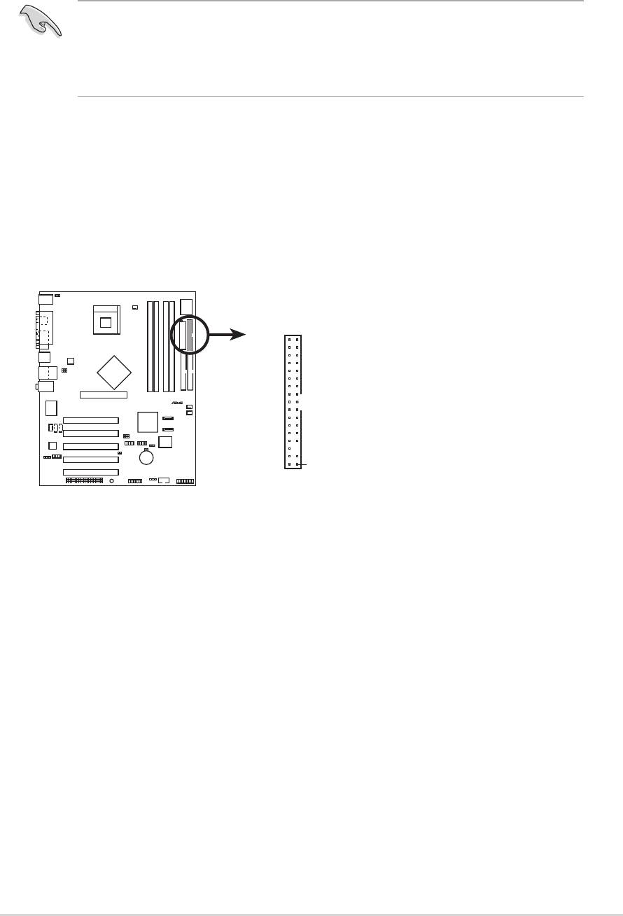
1. Floppy disk drive connector (34-1 pin FLOPPY1)
This connector supports the provided floppy drive ribbon cable. After
connecting one end to the motherboard, connect the other end to the
floppy drive. (Pin 5 is removed to prevent incorrect insertion when
using ribbon cables with pin 5 plug).
P4P800
ASUS P4P800 motherboard user guide
2-23
®
NOTE: Orient the red markings o
n
Always connect ribbon cables with the red stripe to Pin 1 on the
connectors. Pin 1 is usually on the side closest to the power connector
on hard drives and CD-ROM drives, but may be on the opposite side
on floppy disk drives.
FLOPPY1
the floppy ribbon cable to PIN 1.
PIN 1
P4P800 Floppy Disk Drive Connector
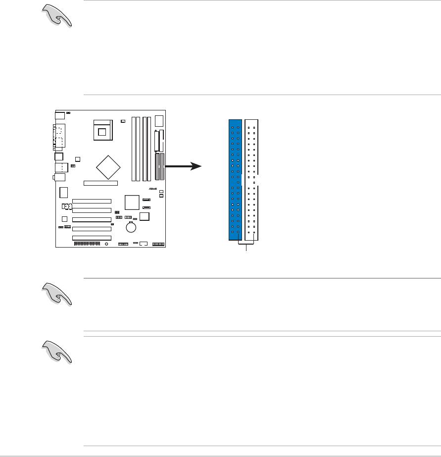
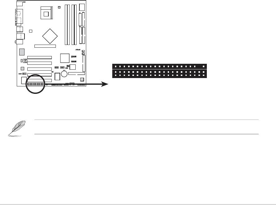
2. IDE connectors (40-1 pin PRI_IDE1, SEC_IDE1)
This connector supports the provided UltraDMA100/66 IDE hard disk
ribbon cable. Connect the cable’s blue connector to the primary
(recommended) or secondary IDE connector, then connect the gray
connector to the UltraDMA100/66 slave device (hard disk drive) and
the black connector to the UltraDMA100/66 master device. It is
recommended that you connect non-UltraDMA100/66 devices to the
secondary IDE connector. If you install two hard disks, you must
configure the second drive as a slave device by setting its jumper
accordingly. Refer to the hard disk documentation for the jumper
settings. BIOS supports specific device bootup. If you have more than
two UltraDMA100/66 devices, purchase another UltraDMA100/66
cable. You may configure two hard disks to be both master devices
with two ribbon cables – one for the primary IDE connector and
another for the secondary IDE connector.
P4P800
2-24
Chapter 2: Hardware information
®
NOTE: Orient the red marking
P4P800 IDE Connectors
s
1. Pin 20 on each IDE connector is removed to match the covered
hole on the UltraDMA cable connector. This prevents incorrect
orientation when you connect the cables.
2. The hole near the blue connector on the UltraDMA100/66 cable is
intentional.
(usually zigzag) on the IDE
ribbon cable to PIN 1.
PRI_IDE1
SEC_IDE1
PIN 1
For UltraDMA100/66 IDE devices, use an 80-conductor IDE cable. The
UltraDMA/66 cable included in the motherboard package also supports
UltraDMA100.
Important notes when using legacy OS
• Refer to page 2-26 on how to configure P-ATA and S-ATA devices
if you installed a legacy operating system (e.g. MS-DOS, Windows
98/ME/NT4.0).
• In legacy OS, manually set DMA mode in Device Manager under
System Properties, if your hard disk supports UDMA mode.
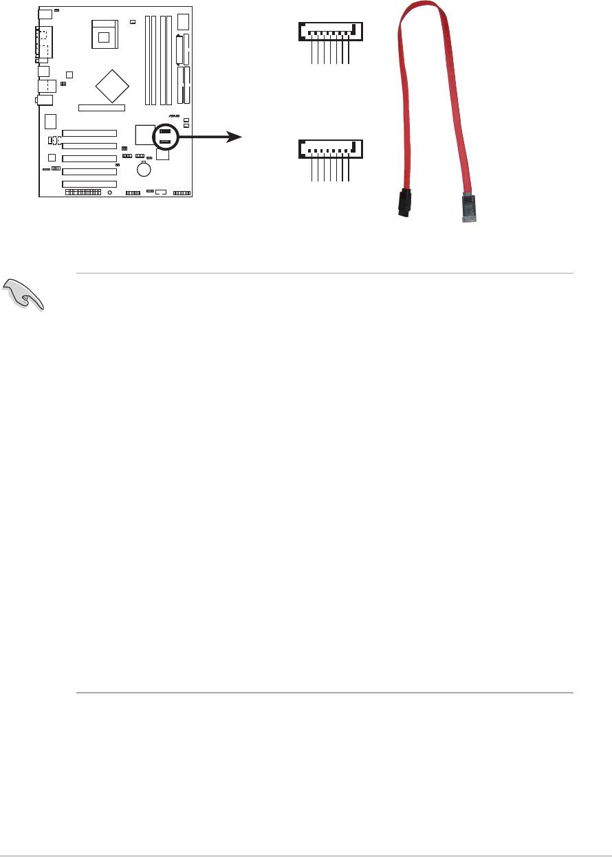
3. Serial ATA connectors (7-pin SATA1, SATA2)
These next generation connectors support the thin Serial ATA cables
for primary internal storage devices. The current Serial ATA interface
allows up to 150 MB/s data transfer rate, faster than the standard
parallel ATA with 133 MB/s (Ultra ATA/133).
P4P800
ASUS P4P800 motherboard user guide
2-25
®
SATA1
GND
GND
GND
RSATA_TXP1
RSATA_TXN1
RSATA_RXP1
RSATA_RXN1
SATA2
GND
GND
GND
P4P800 SATA Connectors
RSATA_TXP2
RSATA_TXN2
RSATA_RXP2
RSATA_RXN2
Important notes on Serial ATA solution:
• In legacy operating system (Win 98, WinME, WinNT, DOS)
environment, using SATA will disable one of the IDE channels from
ICH5R south bridge chipset. See BIOS section for correct setting.
• The Serial ATA cable is smaller and more flexible allowing easier
routing inside the chassis. The lower pin count of the Serial ATA
cable eliminates the problem caused by the wide, flat ribbon cables
of the Parallel ATA interface.
®
• The Serial ATA RAID driver is available for Windows
XP™ only.
• Only RAID 0 is supported.
• Hot plug support for Serial ATA drive and connections are not
available in this motherboard.
®
• Install Windows
XP™ Service Pack 1 when using Serial ATA.
Parallel ATA and Serial ATA device configurations
Following are the Parallel ATA and Serial ATA device configurations
supported by Intel ICH5 specifications.
Native operating systems (OS) are Windows 2000/XP. ICH5R supports a
maximum of six (6) devices using these OS.
Legacy OS are MS-DOS, Windows 98/Me/NT4.0. ICH5R supports a
maximum of four (4) devices using these OS.
P-ATA S-ATA
Operating System Primary Secondary Port 0 Port 1
(2 devices) (2 devices) (1 device) (1 device)
1. Windows 2000/XP
2. Windows 98/Me/NT4.0
Configuration A —
Configuration B —
Configuration C ——
Legend:
Supported
— Disabled
Required IDE Configuration settings in BIOS
Refer to the following table for the appropriate BIOS settings of the above
P-ATA and S-ATA device configurations. See section “4.3.6 IDE
Configuration” for details on the related BIOS items.
Windows Windows 98/Me/NT4.0
BIOS item 2000/XP A B C
Onboard IDE Operate Mode Enhanced Mode Compatible Mode Compatible Mode Compatible Mode
Enhanced Mode Support On S-ATA — — —
IDE Port Settings — Primary P-ATA+S-ATA Sec. P-ATA+S-ATA P-ATA Ports Only
2-26
Chapter 2: Hardware information
5. SMBus connector (6-1 pin SMB1)
This connector allows you to connect SMBus (System Management
Bus) devices. Devices communicate with an SMBus host and/or other
SMBus devices using the SMBus interface.
P4P800
ASUS P4P800 motherboard user guide
2-27
®
SMB1
1
+3V
Ground
SMBCLK
P4P800 SMBus Connector
FLOATING
SMBDATA
6. Chassis intrusion connector (4-1 pin CHASSIS1)
This lead is for a chassis designed with intrusion detection feature.
This requires an external detection mechanism such as a chassis
intrusion sensor or microswitch. When you remove any chassis
component, the sensor triggers and sends a high-level signal to this
lead to record a chassis intrusion event.
By default, the pins labeled “Chassis Signal” and “Ground” are shorted
with a jumper cap. If you wish to use the chassis intrusion detection
feature, remove the jumper cap from the pins.
P4P800
®
CHASSIS
P4P800 Chassis Alarm Lead
1
+5VSB_MB
Chassis Signal
GND
(Default
)
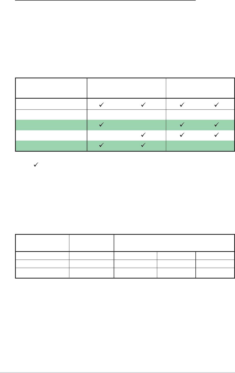
7. CPU, Chassis, and Power Fan Connectors
(3-pin CPU_FAN1, PWR_FAN1, CHA_FAN1)
The fan connectors support cooling fans of 350mA~740mA (8.88W
max.) or a total of 1A~2.22A (26.64W max.) at +12V. Connect the fan
cables to the fan connectors on the motherboard, making sure that the
black wire of each cable matches the ground pin of the connector.
P4P800
2-28
Chapter 2: Hardware information
®
GND
Rotatio
CPU_FAN1
CHA_FAN1
P4P800 12-Volt Fan Connectors
n
Do not forget to connect the fan cables to the fan connectors. Lack of
sufficient air flow within the system may damage the motherboard
components. These are not jumpers! DO NOT place jumper caps on
the fan connectors!
+12V
GND
+12V
Rotation
GND
+12V
Rotation
PWR_FAN1
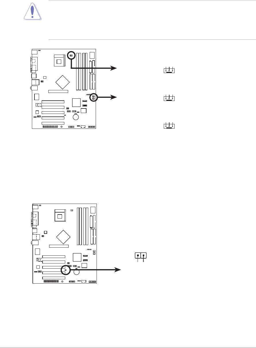
8. Power supply thermal connector (2-pin TRPWR1)
If your power supply has a thermal monitoring feature, connect its
thermal sensor cable to this connector.
P4P800
®
P4P800 Power Supply Thermal Connecto
r
TRPWR1
Ground
TRPWR
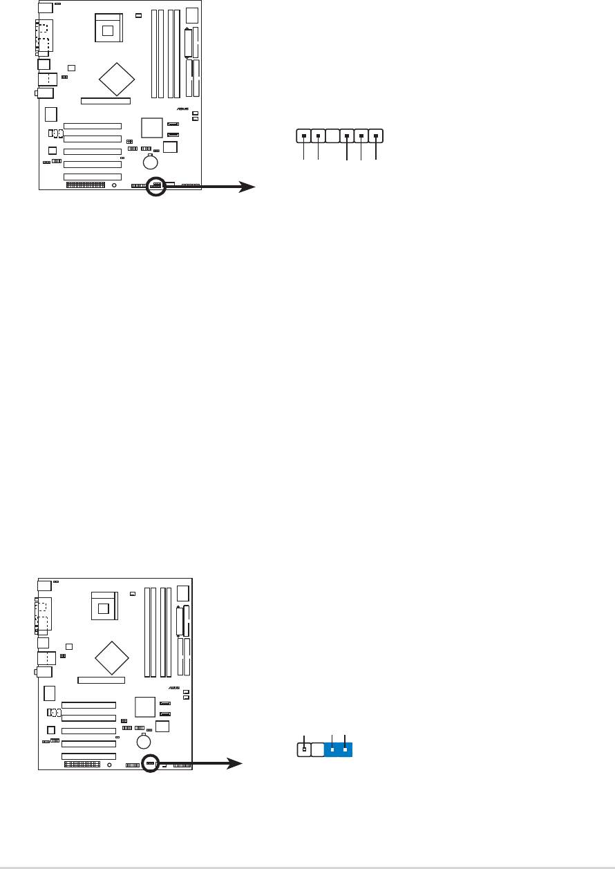
9. ATX power connectors
(20-pin ATXPWR, 4-pin ATX12V)
These connectors connect to an ATX 12V power supply. The plugs
from the power supply are designed to fit these connectors in only one
orientation. Find the proper orientation and push down firmly until the
connectors completely fit.
In addition to the 20-pin ATXPWR1 connector, this motherboard
requires that you connect the 4-pin ATX +12V power plug to provide
sufficient power to the CPU.
P4P800
ASUS P4P800 motherboard user guide
2-29
®
1. Do not forget to connect the 4-pin ATX +12V power plug.
Otherwise, the system does not boot up.
2. Make sure that your ATX 12V power supply can provide 8A on the
+12V lead and at least 1A on the +5-volt standby lead (+5VSB).
The minimum recommended wattage is 230W, or 300W for a fully
configured system. The system may become unstable or may not
boot up if the power is inadequate.
ATXPWR1 ATX12V1
+3.3VDC
+3.3VDC
+12V DC GND
-12.0VDC
+3.3VDC
COM
COM
PS_ON#
+5.0VDC
COM
COM
COM
+5.0VDC
+12V DC GND
COM
COM
-5.0VDC
PWR_OK
+5.0VDC
+5VSB
+5.0VDC
+12.0VDC
P4P800 ATX Power Connector
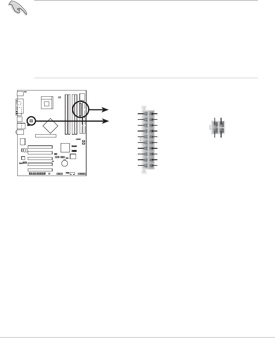
10.USB headers (10-1 pin USB_56, USB_78)
If the USB ports on the rear panel are inadequate, a USB header is
available for additional USB ports. The USB header complies with USB
2.0 specification that supports up to 480 Mbps connection speed. This
speed advantage over the conventional 12 Mbps on USB 1.1 allows
faster Internet connection, interactive gaming, and simultaneous
running of high-speed peripherals.
P4P800
2-30
Chapter 2: Hardware information
®
You must install the driver before you can use the USB 2.0 capability.
USB+5V
USB_P6-
USB_P6+
GND
NC
USB+5V
USB_P8-
USB_P8+
GND
NC
USB56
USB78
1
1
P4P800 USB 2.0 Header
GND
GND
USB+5V
USB_P5-
USB+5V
USB_P5+
USB_P7-
USB_P7+
NEVER connect a 1394 cable to the USB_56 or USB_78 connectors.
Doing so will damage the motherboard!
The USB port is an optional item and not included in this motherboard
package.
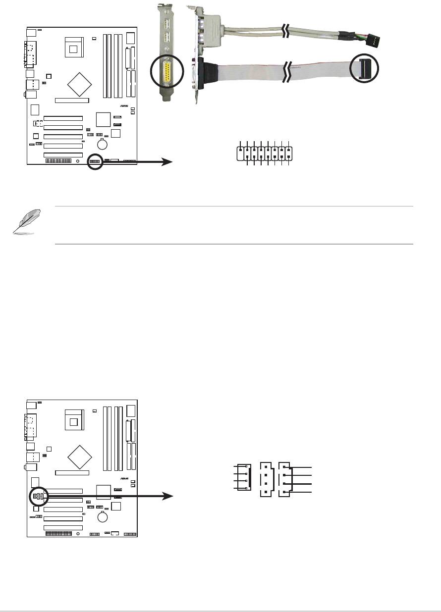
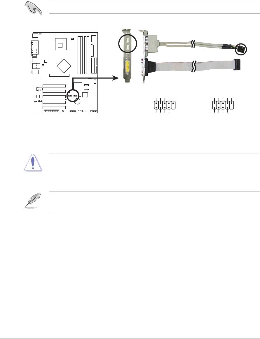
11. GAME/MIDI connector (16-1 pin GAME1)
This connector supports an optional GAME/MIDI module. If a GAME/
MIDI module is available, connect the GAME/MIDI cable to this
connector. The GAME/MIDI port on the module connects a joystick or a
game pad for playing games, and MIDI devices for playing or editing
audio files.
P4P800
12.Internal audio connectors (4-pin CD1, AUX1, MODEM)
These connectors allow you to receive stereo audio input from sound
sources such as a CD-ROM, TV tuner, or MPEG card. The MODEM
connector allows the onboard audio to interface with a voice modem
card with a similar connector. It also allows the sharing of mono_in
(such as a phone) and a mono_out (such as a speaker) between the
audio and a voice modem card.
ASUS P4P800 motherboard user guide
2-31
®
+5V
J1B2
J1CY
GND
GND
J1CX
J1B1
+5V
GAME1
P4P800 Game Connector
+5V
J2B2
J2CY
J2CX
J2B1
MIDI_IN
MIDI_OUT
P4P800
®
Right Audio Channe
CD1(Black) AUX1(White)
P4P800 Internal Audio Connectors
l
The GAME port module is an optional item not included in this
motherboard package.
MODEM
Modem-Out
Ground
Ground
Ground
Ground
Modem-In
Left Audio Channel
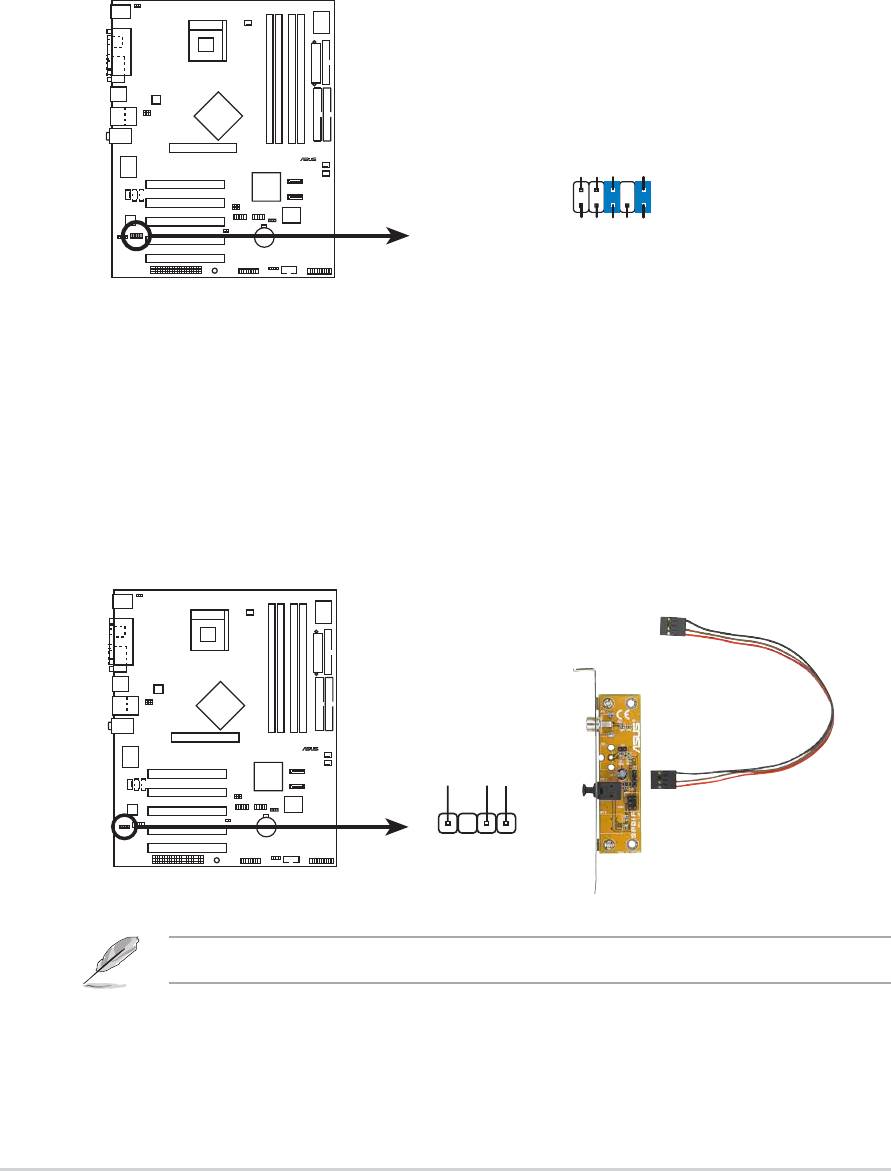
14.Digital Audio connector (6-1 pin SPDIF_OUT)
This connector is for the S/PDIF audio module to allow digital sound
output. Connect one end of the S/PDIF audio cable to this connector
and the other end to the S/PDIF module.
P4P800
2-32
Chapter 2: Hardware information
®
13.Front panel audio connector (10-1 pin FP_AUDIO)
This is an interface for the Intel front panel audio cable that allow
convenient connection and control of audio devices.
By default, the pins labeled LINE_OUT_R/BLINE_OUT_R and the pins
LINE_OUT_L/BLINE_OUT_L are shorted with jumper caps. Remove
the caps only when you are connecting the front panel audio cable.
P4P800
SPDIF_OUT
+5V
SPDIFOUT
GND
P4P800 Digital Audio Connector
®
AGND
+5VA
BLINE_OUT_R
BLINE_OUT_L
FP_AUDIO
NC
MIC2
MICPWR
Line out_R
Line out_L
P4P800 Front Panel Audio Connector
The S/PDIF module is not included in this motherboard package.
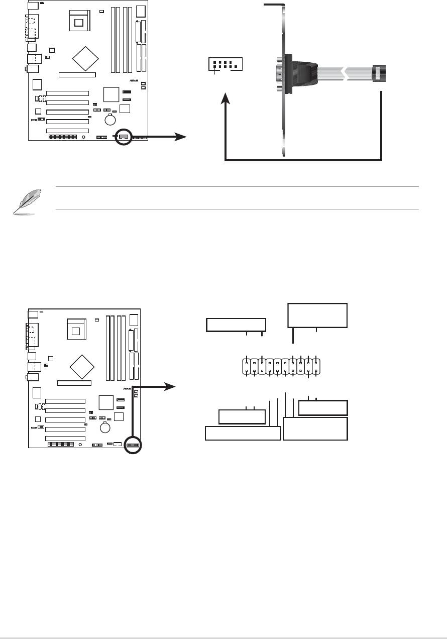
15. Serial Port 2 connector (10-1 pin COM2)
This connector accomodates a second serial port using an optional
serial port bracket. Connect the bracket cable to this connector then
install the bracket into a slot opening at the back of the system chassis.
P4P800
ASUS P4P800 motherboard user guide
2-33
®
COM2
PIN 1
P4P800 Serial COM2 Bracket
The COM2 module is not included in this motherboard package.
16.System panel connector (20-pin PANEL)
This connector accommodates several system front panel functions.
P4P800
®
*
Requires an ATX power supply
P4P800 System Panel Connectors
.
Speaker
Connector
Power LED
PLED+
PLED-
+5V
Ground
Ground
Speaker
PWR
Ground
Ground
Reset
ExtSMI#
Ground
IDE_LED+
IDE_LED-
Reset SW
IDE_LED
ATX Power
SMI Lead
Switch*
• System Power LED Lead (3-1 pin PLED)
This 3-1 pin connector connects to the system power LED. The LED
lights up when you turn on the system power, and blinks when the
system is in sleep mode.

• System Warning Speaker Lead (4-pin SPKR)
This 4-pin connector connects to the case-mounted speaker and
allows you to hear system beeps and warnings.
• System Management Interrupt Lead (2-pin SMI)
This 2-pin connector allows you to manually place the system into a
suspend mode, or “green” mode, where system activity is instantly
decreased to save power and to expand the life of certain system
components. Attach the case-mounted suspend switch to this 2-pin
connector.
• ATX Power Switch / Soft-Off Switch Lead (2-pin PWRBTN)
This connector connects a switch that controls the system power.
Pressing the power switch turns the system between ON and SLEEP,
or ON and SOFT OFF, depending on the BIOS or OS settings.
Pressing the power switch while in the ON mode for more than 4
seconds turns the system OFF.
• Reset Switch Lead (2-pin RESET)
This 2-pin connector connects to the case-mounted reset switch for
rebooting the system without turning off the system power.
• Hard disk activity LED (2-pin IDE_LED)
This connector supplies power to the hard disk activity LED. Any read
or write activity of an IDE device cause this LED to light up.
2-34
Chapter 2: Hardware information
