Asus P4P800: Chapter 4
Chapter 4: Asus P4P800

Chapter 4
This chapter gives information about the
ASUS P4P800 Basic Input/Output System
(BIOS).This chapter includes updating the
BIOS using the AFUDOS.EXE utility that is
bundled with the support CD.
BIOS setup

Chapter summary
4.1 Managing and updating your BIOS .............. 4-1
4.2 BIOS Setup program...................................... 4-6
4.3 Main Menu .................................................... 4-10
4.4 Advanced Menu ........................................... 4-15
4.5 Power Menu.................................................. 4-26
4.6 Boot Menu .................................................... 4-31
4.7 Exit Menu ...................................................... 4-36
ASUS P4SDX Deluxe motherboard

4.1 Managing and updating your BIOS
• The original BIOS file for this motherboard is in the support CD.
• Copy the original BIOS to a bootable floppy disk in case you
need to restore the BIOS in the future.
4.1.1 Creating a bootable floppy disk
1. Do either one of the following to create a bootable floppy disk.
DOS environment
Insert a 1.44 MB floppy disk into the drive. At the DOS prompt, type:
format A:/S , then press the <Enter> key
Windows environment
a. From your Windows desktop, click on Start, point to Settings, then
click on Control Panel.
b. Double-click on Add/Remove Programs icon from the Control
Panel window.
c. Click on the Startup Disk tab, then on Create Disk... button.
d. Insert a 1.44 MB floppy disk when prompted. Follow the suceeding
screen instructions to complete the process.
2. Copy the original (or the latest) motherboard BIOS to the bootable
floppy disk.
4.1.2 Using AFUDOS to update the BIOS
Update the BIOS using the AFUDOS.EXE utility in DOS environment.
1. Visit the ASUS website (www.asus.com) to download the latest BIOS
file for your motherboard. Save the BIOS file to a bootable floppy disk.
Write down the BIOS file name to a piece of paper. You need to type
the exact BIOS file name at the prompt.
2. Copy the AFUDOS.EXE utility from the support CD to the bootable
floppy disk that contains the BIOS file.
3. Boot the system from the floppy disk.
ASUS P4P800 motherboard user guide
4-1

4. At the DOS prompt, type the command line:
afudos /i<filename>
where “filename” means the latest (or original) BIOS file that you
copied to the bootable floppy disk.
The screen displays the status of the update process.
The BIOS information on the screen is for reference only. What you
see on your screen may not be exactly the same as shown.
A:\>afudos /iP4P800.rom
AMI Firmware Update Utility - Version 1.10
Copyright (C) 2002 American Megatrends, Inc. All rights reserved.
Reading file ..... done
Erasing flash .... done
Writing flash .... 0x0008CC00 (9%)
DO NOT shutdown or reset the system while updating the BIOS! Doing
so may cause system boot failure!
When the BIOS update process is complete, the utility returns to the
DOS prompt.
A:\>afudos /iP4P800.rom
AMI Firmware Update Utility - Version 1.10
Copyright (C) 2002 American Megatrends, Inc. All rights reserved.
Reading file ..... done
Erasing flash .... done
Writing flash .... 0x0008CC00 (9%)
Verifying flash .. done
A:\>
5. Reboot the system from the hard disk.
4-2
Chapter 4: BIOS Setup

4.1.3 Using AFUDOS to copy BIOS from PC
The AFUDOS.EXE utility can also be used to copy the current system
BIOS settings to a floppy or hard disk. The copy can be used as a backup
in case the system BIOS fails or gets corrupted.
1. At the DOS prompt, type the command line:
afudos /o<filename>
where “filename” can be any user provided filename of not more than
eight (8) alpha-numeric characters for the main filename and three (3)
alpha-numeric characters for the extension name.
Press the Enter key.
The BIOS information on the screen is for reference only. What you
see on your screen may not be exactly the same as shown.
Main filename
Extension name
A:\>afudos /oMYBIOS03.rom
AMI Firmware Update Utility - Version 1.10
Copyright (C) 2002 American Megatrends, Inc. All rights reserved.
Reading flash ..... 0x0008CC00 (9%)
2. The utility will copy the current system BIOS by default to the floppy
disk. Make sure that the floppy disk is not write-protected and have
enough space (at least 600KB) to store the file.
A:\>afudos /oMYBIOS03.rom
AMI Firmware Update Utility - Version 1.10
Copyright (C) 2002 American Megatrends, Inc. All rights reserved.
Reading flash ..... done
A:\>
When the BIOS copy process is complete, the utility returns to the
DOS prompt.
ASUS P4P800 motherboard user guide
4-3

4.1.4 Using ASUS EZ Flash to update the BIOS
The ASUS EZ Flash feature allows you to easily update the BIOS without
having to go through the long process of booting from a diskette and using
a DOS-based utility. The EZ Flash is built-in the BIOS firmware so it is
accessible by simply pressing <Alt> + <F2> during the Power-On Self
Tests (POST).
To update the BIOS using ASUS EZ Flash:
1. Visit the ASUS website (www.asus.com) to download the latest BIOS
file for your motherboard and rename the downloaded file as
P4P800.ROM. Save the BIOS file to a floppy disk.
2. Reboot the system.
3. To launch EZ Flash, press <Alt> + <F2> during POST to display the
following.
User recovery requested. Starting BIOS recovery...
Checking for floppy...
• If there is no floppy disk found in the drive, the error message
“Floppy not found!” appears.
• If the correct BIOS file is not found in the floppy disk, the error
message “P4P800.ROM not found!” is displayed. Make sure to
rename the downloaded BIOS file as “P4P800.ROM”.
4. Insert the floppy disk that contains the BIOS file. If all the necessary
files are found in the floppy disk, EZ Flash performs the BIOS update
process and automatically reboots the system when done.
DO NOT shutdown or reset the system while updating the BIOS! Doing
so may cause system boot failure!
User recovery requested. Starting BIOS recovery...
Checking for floppy...
Floppy found!
Reading file “P4P800.rom”. Completed.
Start flashing...
Flashed successfully. Rebooting.
4-4
Chapter 4: BIOS Setup

4.1.5 Recovering the BIOS with CrashFree BIOS 2
The CrashFree BIOS 2 auto recovery tool allows you to restore BIOS from
the motherboard support CD, or from a floppy disk that contains the BIOS
file, in case the current BIOS on the motherboard fails or gets corrupted.
1. Prepare the support CD that came with the motherboard or a
floppy disk that contains the motherboard BIOS before
proceeding with the BIOS update process.
2. If you have saved a copy of the original motherboard BIOS to a
bootable floppy disk, you may also use this disk to restore the
BIOS. See section “4.1.1 Creating a bootable floppy disk.”
To recover the BIOS from a floppy disk:
1. Boot the system.
2. When a corrupted BIOS is detected, the following screen message
appears.
Bad BIOS checksum. Starting BIOS recovery...
Checking for floppy...
3. Insert a floppy disk that contains the original or the latest BIOS file for
this motherboard. If all the necessary files are found in the floppy disk,
the BIOS update process continues.
Make sure that the BIOS file in the floppy disk is renamed as
“P4P800.ROM”.
Bad BIOS checksum. Starting BIOS recovery...
Checking for floppy...
Floppy found!
Reading file “P4P800.rom”. Completed.
Start flashing...
DO NOT shutdown or reset the system while updating the BIOS! Doing
so may cause system boot failure!
4. When the BIOS update process is complete, reboot the system.
ASUS P4P800 motherboard user guide
4-5

To recover the BIOS from the support CD:
1. Boot the system.
2. When a corrupted BIOS is detected, the following screen message
appears.
Bad BIOS checksum. Starting BIOS recovery...
Checking for floppy...
If there is no floppy disk found in the drive, the system automatically
checks the CD-ROM.
3. Place the support CD in the CD-ROM. The support CD contains the
original BIOS for this motherboard.
Bad BIOS checksum. Starting BIOS recovery...
Checking for floppy...
Floppy not found!
Checking for CD-ROM...
CD-ROM found.
Reading file “P4P800.rom”. Completed.
Start flashing...
DO NOT shutdown or reset the system while updating the BIOS! Doing
so may cause system boot failure!
4. When the BIOS update process is complete, reboot the system.
The recovered BIOS may not be the latest BIOS version for this
motherboard. Visit ASUS website (www.asus.com) to download the
latest BIOS file.
4-6
Chapter 4: BIOS Setup

4.2 BIOS Setup program
This motherboard supports a programmable firmware hub (FWH) that you
can update using the provided utility described in section “4.1 Managing
and updating your BIOS.”
Use the BIOS Setup program when you are installing a motherboard,
reconfiguring your system, or prompted to “Run Setup”. This section
explains how to configure your system using this utility.
Even if you are not prompted to use the Setup program, you may want to
change the configuration of your computer in the future. For example, you
may want to enable the security password feature or change the power
management settings. This requires you to reconfigure your system using
the BIOS Setup program so that the computer can recognize these
changes and record them in the CMOS RAM of the firmware hub.
The firmware hub on the motherboard stores the Setup utility. When you
start up the computer, the system provides you with the opportunity to run
this program. Press <Delete> during the Power-On Self Test (POST) to
enter the Setup utility. Otherwise, POST continues with its test routines.
If you wish to enter Setup after POST, restart the system by pressing
<Ctrl> + <Alt> + <Delete>, or by pressing the reset button on the system
chassis. You can also restart by turning the system off and then back on.
Do this last option only if the first two failed.
The Setup program is designed to make it as easy to use as possible. It is
a menu-driven program, which means you can scroll through the various
sub-menus and make your selections from the available options using the
navigation keys.
The default BIOS settings for this motherboard apply for most
conditions to ensure optimum performance. If the system becomes
unstable after changing any BIOS settings, load the default settings to
ensure system compatibility and stability. Select the Load Default
Settings item under the Exit Menu. See section “4.7 Exit Menu.”
The BIOS setup screens shown in this chapter are for reference
purposes only, and may not exactly match what you see on your
screen.
Visit the ASUS website (www.asus.com) to download the latest product
and BIOS information.
ASUS P4P800 motherboard user guide
4-7

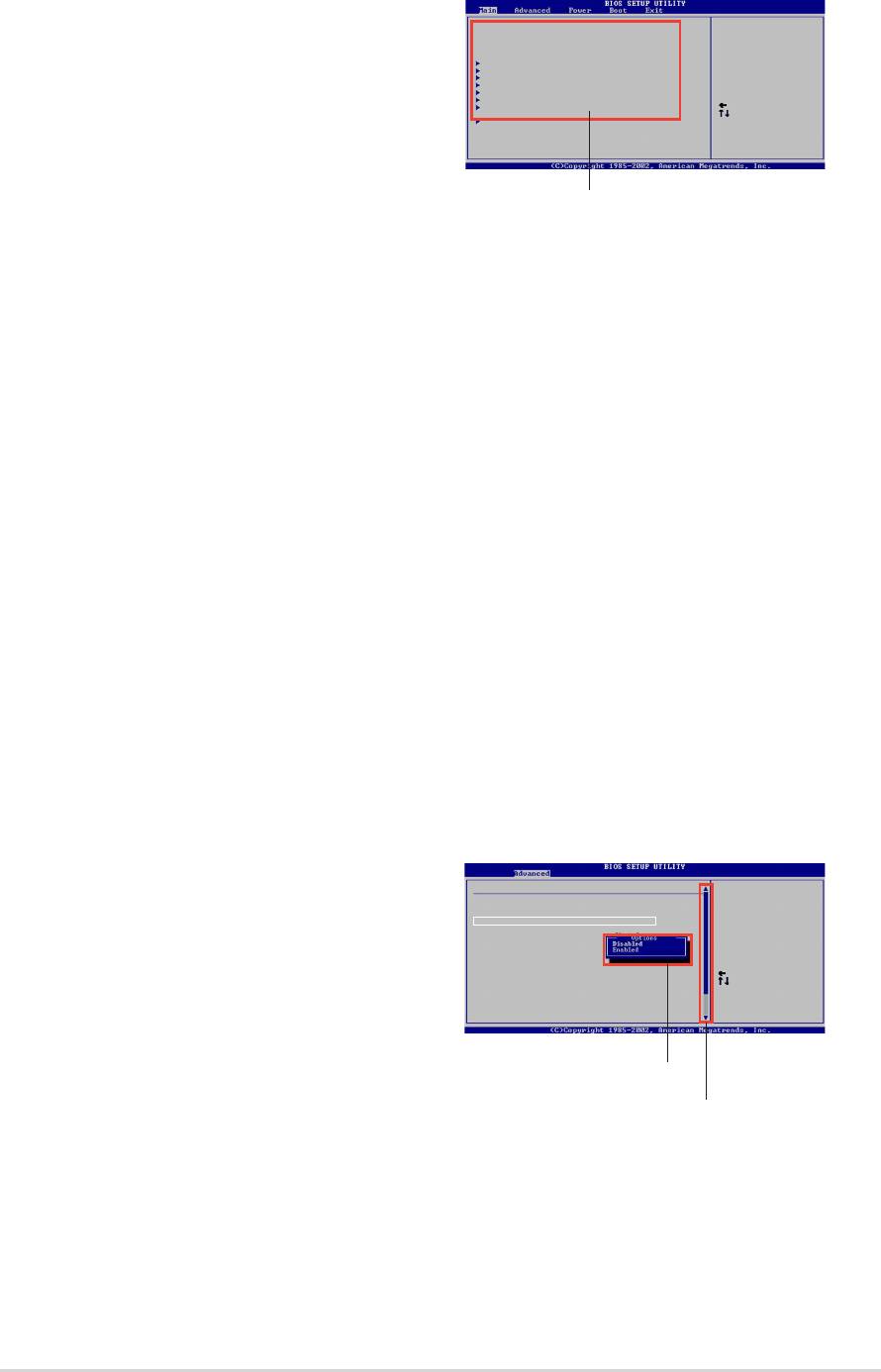
4.2.1 BIOS menu screen
Menu items
Configuration fields
General helpMenu bar
System Time [11:10:19]
Use [ENTER], [TAB]
System Date [Thu 03/27/2003]
or [SHIFT-TAB] to
Legacy Diskette A [1.44M, 3.5 in]
select a field.
Language [English]
Use [+] or [-] to
Primary IDE Master :[ST320413A]
configure system time.
Primary IDE Slave :[ASUS CD-S340]
Secondary IDE Master :[Not Detected]
Secondary IDE Slave :[Not Detected]
Third IDE Master :[Not Detected]
Fourth IDE Master :[Not Detected]
IDE Configuration
Select Screen
Select Item
System Information
+- Change Field
Tab Select Field
F1 General Help
F10 Save and Exit
ESC Exit
Sub-menu items
Navigation keys
4.2.2 Menu bar
The menu bar on top of the screen has the following main items:
Main For changing the basic system configuration
Advanced For changing the advanced system settings
Power For changing the advanced power management (APM)
configuration
Boot For changing the system boot configuration
Exit For selecting the exit options and loading default settings
To select an item on the menu bar, press the right or left arrow key on the
keyboard until the desired item is highlighted.
4.2.3 Navigation keys
At the bottom right corner of a menu screen are the navigation keys for
that particular menu. Use the navigation keys to select items in the menu
and change the settings.
Some of the navigation keys differ from one screen to another.
4-8
Chapter 4: BIOS Setup
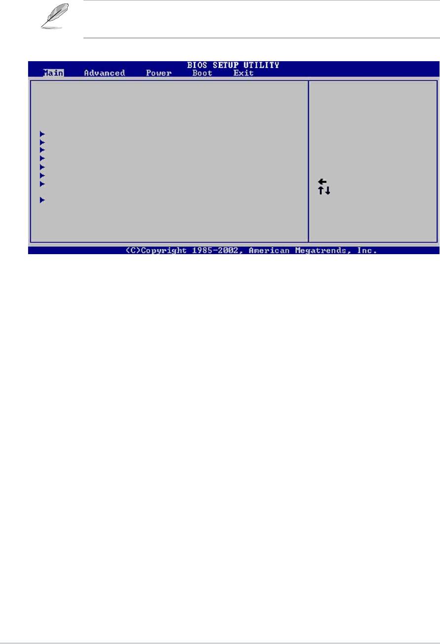
4.2.4 Menu items
The highlighted item on the menu bar
System Time [11:10:19]
Use [ENTER], [TAB]
System Date [Thu 03/27/2003]
or [SHIFT-TAB] to
Legacy Diskette A [1.44M, 3.5 in]
select a field.
Language [English]
displays the specific items for that menu.
Use [+] or [-] to
Primary IDE Master :[ST320413A]
configure system time.
Primary IDE Slave :[ASUS CD-S340]
Secondary IDE Master :[Not Detected]
Secondary IDE Slave :[Not Detected]
For example, selecting Main shows the
Third IDE Master :[Not Detected]
Fourth IDE Master :[Not Detected]
IDE Configuration
Select Screen
Select Item
Main menu items.
System Information
+- Change Field
Tab Select Field
F1 General Help
F10 Save and Exit
ESC Exit
The other items (Advanced, Power,
Main menu items
Boot, and Exit) on the menu bar have
their respective menu items.
4.2.5 Sub-menu items
An item with a sub-menu on any menu screen is distinguished by a solid
triangle before the item. To display the sub-menu, select the item and
press Enter.
4.2.6 Configuration fields
These fields show the values for the menu items. If an item is user-
configurable, you may change the value of the field opposite the item. You
can not select an item that is not user-configurable.
A configurable field is enclosed in brackets, and is highlighted when
selected. To change the value of a field, select it then press Enter to
display a list of options. Refer to “4.2.7 Pop-up window.”
4.2.7 Pop-up window
Select a menu item then press Enter to
Advanced Chipset settings
display a pop-up window with the
WARNING: Setting wrong values in the sections below
may cause system to malfunction.
Configure DRAM Timing by SPD [Enabled]
configuration options for that item.
Performance Acceleration Mode [Auto]
DRAM Idle Timer [Auto]
DRAm Refresh Rate [Auto]
Graphic Adapter Priority [AGP/PCI]
Graphics Aperture Size [ 64 MB]
Spread Spectrum [Enabled]
Select Screen
Select Item
ICH Delayed Transaction [Enabled]
+- Change Option
4.2.8 Scroll bar
F1 General Help
MPS Revision [1.4]
F10 Save and Exit
ESC Exit
A scroll bar appears on the right side of
a menu screen when there are items
Pop-up window
that do not fit on the screen. Press Up/
Scroll bar
Down arrow keys or PageUp/
PageDown keys to display the other items on the screen.
4.2.9 General help
At the top right corner of the menu screen is a brief description of the
selected item.
ASUS P4P800 motherboard user guide
4-9
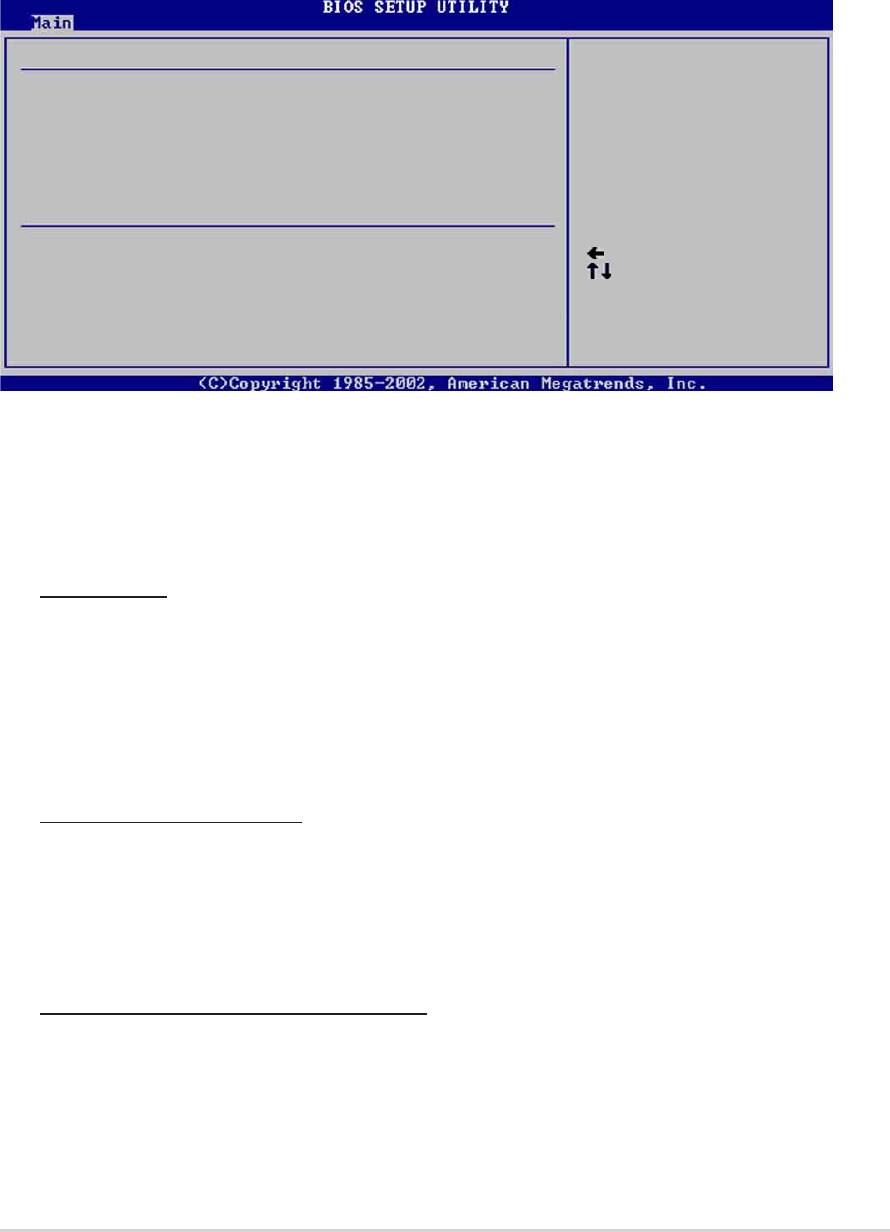
4.3 Main menu
When you enter the BIOS Setup program, the Main menu screen appears
giving you an overview of the basic system information.
Refer to section “4.2.1 BIOS menu screen” for information on the
menu screen items and how to navigate through them.
System Time [11:10:19]
Use [ENTER], [TAB]
System Date [Thu 03/27/2003]
or [SHIFT-TAB] to
Legacy Diskette A [1.44M, 3.5 in]
select a field.
Language [English]
Use [+] or [-] to
Primary IDE Master :[ST320413A]
configure system time.
Primary IDE Slave :[ASUS CD-S340]
Secondary IDE Master :[Not Detected]
Secondary IDE Slave :[Not Detected]
Third IDE Master :[Not Detected]
Fourth IDE Master :[Not Detected]
IDE Configuration
Select Screen
Select Item
System Information
+- Change Field
Tab Select Field
F1 General Help
F10 Save and Exit
ESC Exit
4.3.1 System Time [xx:xx:xxxx]
This item allows you to set the system time.
4.3.2 System Date [Day xx/xx/xxxx]
This item allows you to set the system date.
4.3.3 Legacy Diskette A [1.44M, 3.5 in.]
Sets the type of floppy drive installed. Configuration options: [Disabled]
[360K, 5.25 in.] [1.2M , 5.25 in.] [720K , 3.5 in.] [1.44M, 3.5 in.] [2.88M,
3.5in.]
4.3.4 Language [English]
This field allows you to choose the BIOS language version from the
available options.
4-10
Chapter 4: BIOS Setup
4.3.5 Primary and Secondary IDE Master/Slave;
Third and Fourth IDE Master
While entering Setup, BIOS auto-detects the presence of IDE devices.
There is a separate sub-menu for each IDE device. Select a device item
then press Enter to display the IDE device information.
Primary IDE Master
Select the type
Device : Hard Disk
of device connected
Vendor : ST320413A
to the system.
Size : 20.0GB
LBA Mode : Supported
Block Mode : 16 Sectors
PIO Mode : Supported
Async DMA : MultiWord DMA-2
Ultra DMA : Ultra DMA-5
SMART Monitoring: Supported
Type
[Auto]
Select Screen
LBA/Large Mode
[Auto]
Select Item
Block (Multi-sector Transfer)
[Auto]
+- Change Option
PIO Mode
[Auto]
F1 General Help
DMA Mode
[Auto]
F10 Save and Exit
Smart Monitoring
[Auto]
ESC Exit
32Bit Data Transfer
[Disabled]
The values opposite the dimmed items (Device, Vendor, Size, LBA Mode,
Block Mode, PIO Mode, Async DMA, Ultra DMA, and SMART monitoring)
are auto-detected by BIOS and are not user-configurable. These items
show N/A if no IDE device is installed in the system.
Type [Auto]
Selects the type of IDE drive. Setting to Auto allows automatic
selection of the appropriate IDE device type. Select CDROM if you are
specifically configuring a CD-ROM drive. Select ARMD (ATAPI
Removable Media Device) if your device is either a ZIP, LS-120, or MO
drive. Configuration options: [Not Installed] [Auto] [CDROM] [ARMD]
LBA/Large Mode [Auto]
Enables or disables the LBA mode. Setting to Auto enables the LBA
mode if the device supports this mode, and if the device was not
previously formatted with LBA mode disabled. Configuration options:
[Disabled] [Auto]
Block (Multi-sector Transfer) [Auto]
Enables or disables data multi-sectors transfers. When set to Auto, the
data transfer from and to the device occurs multiple sectors at a time if
the device supports multi-sector transfer feature. When set to
Disabled, the data transfer from and to the device occurs one sector at
a time. Configuration options: [Disabled] [Auto]
ASUS P4P800 motherboard user guide
4-11

PIO Mode [Auto]
Selects the PIO mode. Configuration options: [Auto] [0] [1] [2] [3] [4]
DMA Mode [Auto]
Selects the DMA mode. Configuration options: [Auto] [SWDMA0]
[SWDMA1] [SWDMA2] [MWDMA0] [MWDMA1] [MWDMA2] [UDMA0]
[UDMA1] [UDMA2] [UDMA3] [UDMA4] [UDMA5]
SMART Monitoring [Auto]
Sets the Smart Monitoring, Analysis, and Reporting Technology.
Configuration options: [Auto] [Disabled] [Enabled]
32Bit Data Transfer [Disabled]
Enables or disables 32-bit data transfer. Configuration options:
[Disabled] [Enabled]
4.3.6 IDE Configuration
The items in this menu allow you to set or change the configurations for
the IDE devices installed in the system. Select an item then press Enter if
you wish to configure the item.
IDE Configuration
Onboard IDE Operate Mode [Enhanced Mode]
Enhanced Mode Support On [P-ATA + S-ATA]
Configure S-ATA as RAID [No]
IDE Detect Time Out (Sec) [35]
Select Screen
Select Item
+- Change Option
F1 General Help
F10 Save and Exit
ESC Exit
Onboard IDE Operate Mode [Enhanced Mode]
Allows selection of the IDE operation mode depending on the operating
system (OS) that you installed. Set to Enhanced Mode if you are using
native OS, such as Windows 2000/XP. Set to Compatible Mode if you are
using legacy OS including MS-DOS, Windows ME/98/NT4.0.
Configuration options: [Compatible Mode] [Enhanced Mode]
4-12
Chapter 4: BIOS Setup

Refer to the section “Parallel ATA and Serial ATA device configurations”
on page 2-24 for the appropriate settings of the IDE Configuration
items under different operating systems.
Enhanced Mode Support On [S-ATA]
The default setting S-ATA allows you to use native OS on Serial ATA
and Parallel ATA ports. We recommend that you do not change the
default setting for better OS compatibility. In this setting, you may use
legacy OS on the Parallel ATA ports only if you did not install any
Serial ATA device.
The P-ATA+S-ATA and P-ATA options are for advanced users only. If
you set to any of these options and encounter problems, revert to the
default setting S-ATA.
Configuration options: [P-ATA+S-ATA] [S-ATA] [P-ATA]
The Enhanced Mode Support On appears only when the item
Onboard IDE Operate Mode is set to Enhanced Mode.
Configure S-ATA as RAID [No]
This field configures the S-ATA to function as an IDE controller or
RAID. Configuration options: [Yes] [No]
Serial ATA BOOTROM [Enabled]
This field enables or disables the Serial ATA boot ROM.
Configuration options: [Disabled] [Enabled]
The Serial ATA BOOTROM item appears only when the item
Configure S-ATA as RAID is set to [Yes].
IDE Port Settings [Primary P-ATA+S-ATA]
Allows selection of the IDE ports to activate if you are using a legacy
operating system. Set to [Primary P-ATA+S-ATA] if you wish to use the
primary Parallel ATA and Serial ATA ports, or set to [Secondary
P-ATA+SATA] to enable the secondary P-ATA port instead. Setting to
[P-ATA Ports Only] disables the two Serial ATA ports supported by
ICH5. Configuration options: [Primary P-ATA+S-ATA] [Secondary
P-ATA+S-ATA] [P-ATA Ports Only]
The IDE Port Settings appears only when the item Onboard IDE
Operate Mode is set to Compatible Mode.
IDE Detect Time Out [35]
Selects the time out value for detecting ATA/ATAPI devices. Configuration
options: [0] [5] [10] [15] [20] [25] [30] [35]
ASUS P4P800 motherboard user guide
4-13

4.3.7 System Information
This menu gives you an overview of the general system specifications.
The items in this menu are auto-detected by BIOS.
AMI BIOS
Version : 08.00.08
Build Date : 04/03/03
ID : P4P81035
Processor
Type : Intel(R) Pentium(R) 4 CPU 1.73GHz
Speed : 1733 MHz
Count : 1
System Memory
Size : 256MB
Select Screen
Select Item
+- Change Option
F1 General Help
F10 Save and Exit
ESC Exit
AMI BIOS
This item displays the auto-detected BIOS information.
Processor
This item displays the auto-detected CPU specification.
System Memory
This item displays the auto-detected system memory.
4-14
Chapter 4: BIOS Setup
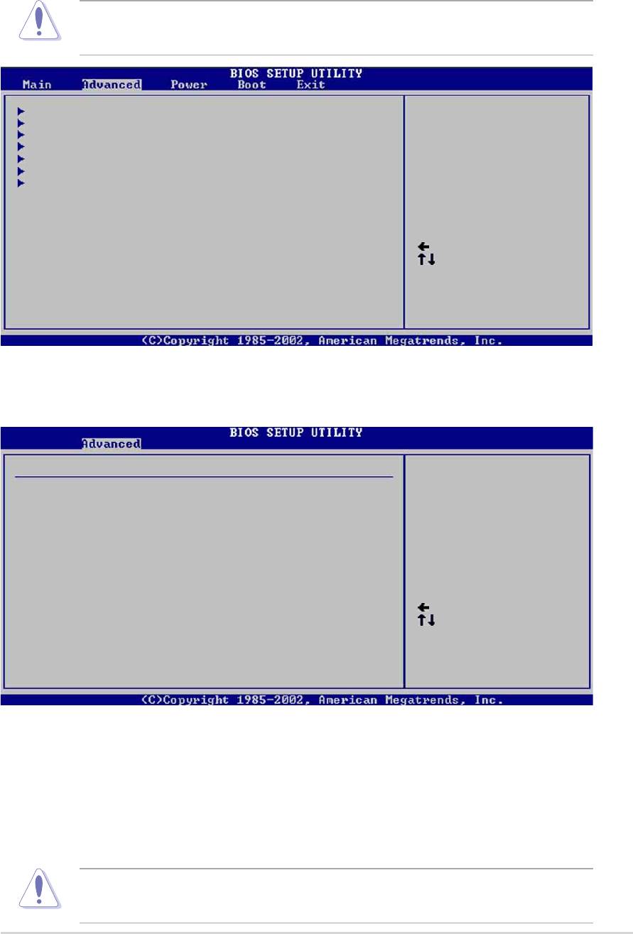
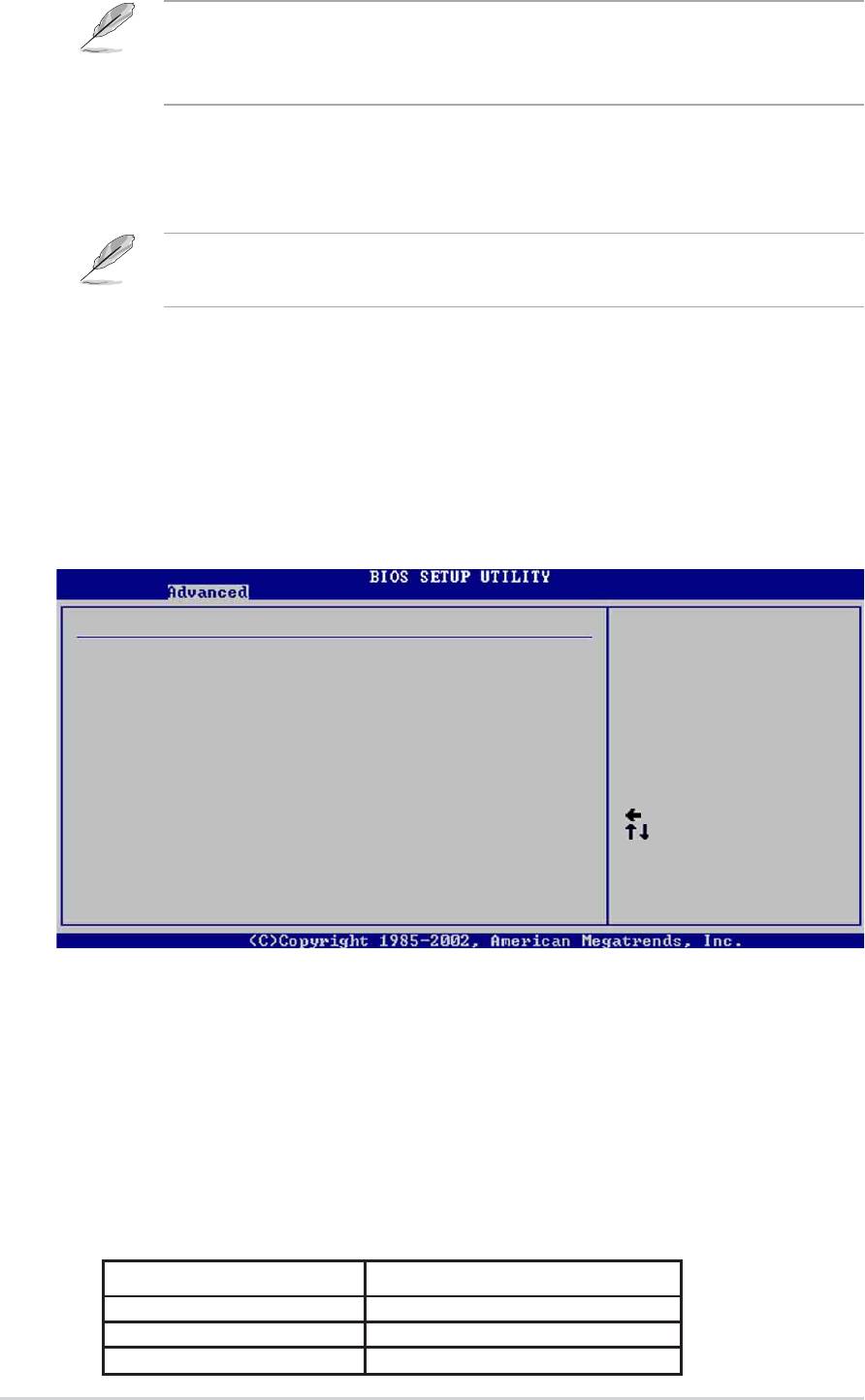
4.4 Advanced menu
The Advanced menu items allow you to change the settings for the CPU
and other system devices.
Take caution when changing the settings of the Advanced menu items.
Incorrect field values may cause the system to malfunction.
JumperFree Configuration
Configure CPU.
CPU Configuration
Chipset
Onboard Devices Configuration
PCI PnP
USB Configuration
Instant Music Configuration
Select Screen
Select Item
Enter Go to Sub-screen
F1 General Help
F10 Save and Exit
ESC Exit
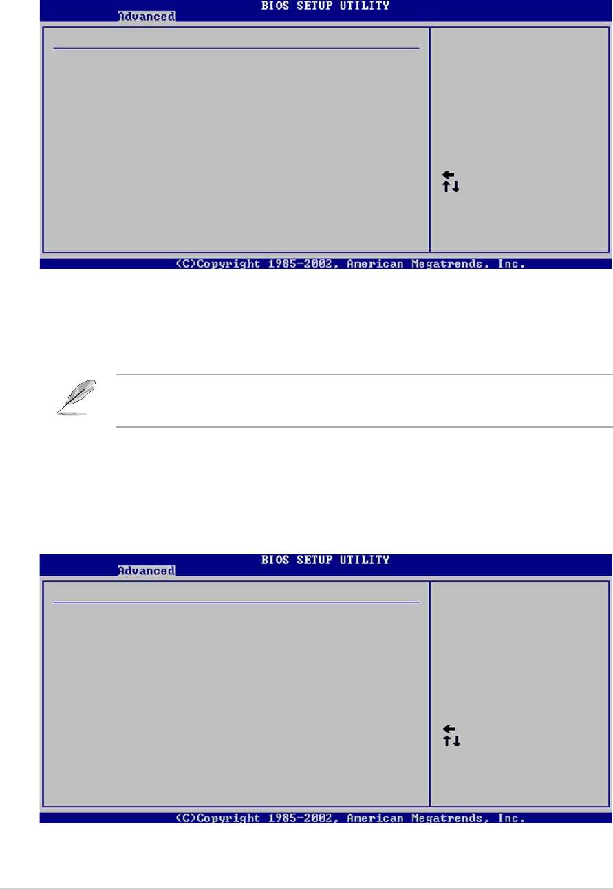
4.4.1 JumperFree Configuration
Configure System Frequency/Voltage
AI Overclock Tuner [Standard]
CPU Ratio [12]
Performance Mode [Auto]
Select Screen
Select Item
+- Change Option
F1 General Help
F10 Save and Exit
ESC Exit
AI Overclock Tuner [Standard]
Allows selection of CPU overclocking options to achieve desired CPU
internal frequency. Select either one of the preset overclocking options.
Configuration options: [Manual] [Standard] [Overclock 5%] [Overclock
10%] [Overclock 20%] [Overclock 30]
Selecting a very high CPU frequency may cause the system to
become unstable! If this happens, revert to the default setting.
ASUS P4P800 motherboard user guide
4-15
If you are using an unlocked CPU, the item CPU Ratio appears under
the AI Overclock Tuner item. You may select your desired ratio from
the available options.
CPU Ratio [12]
This field sets the ratio between the CPU Core Clock and the Front Side
Bus (FSB) Frequency.
If an invalid ratio is set in CMOS, the actual and setpoint values may
differ.
Performance Mode [Auto]
Allows enhanced system performance. Setting to [Turbo] may cause the
system to become unstable. If this happens, revert to the default setting
[Auto]. Configuration options: [Auto] [Standard] [Turbo]
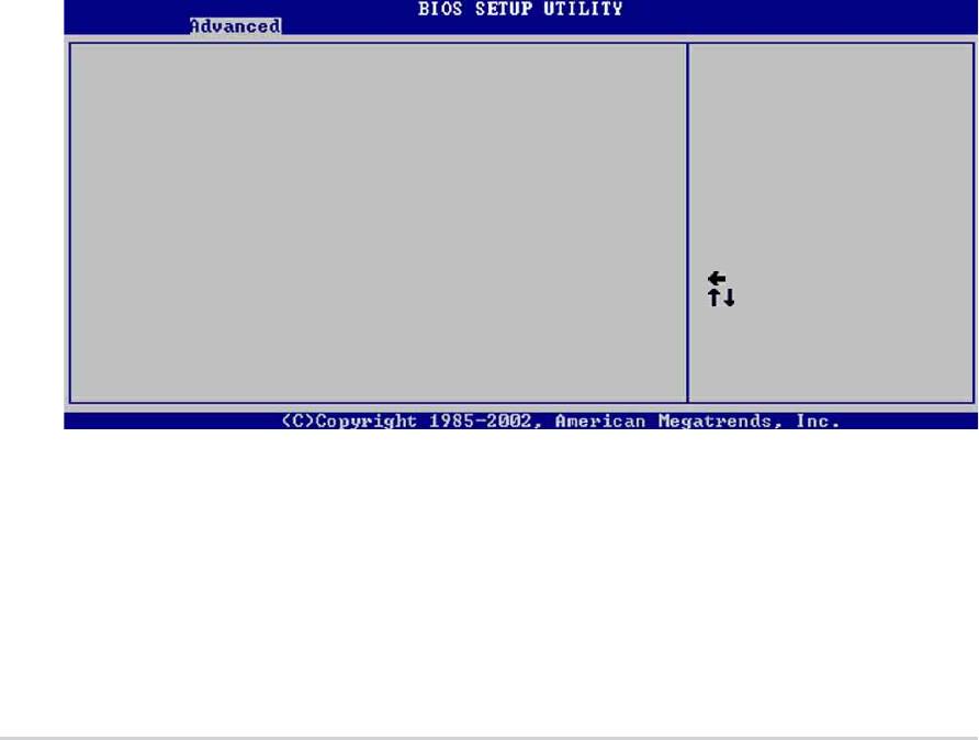
When you set the AI Overclocking Tuner item to [Manual], the related
overclocking items appear.
Configure System Frequency/Voltage
AI Overclock Tuner [Manual]
CPU External Frequency (MHz) [100]
CPU Ratio [12]
DRAM Frequency [Auto]
AGP/PCI Frequency (MHz) [Auto]
CPU VCore Offset to .IV [Disabled]
DDR Reference Voltage [Auto]
AGP VDDQ Voltage [1.50V]
Select Screen
Performance Mode [Auto]
Select Item
+- Change Option
F1 General Help
F10 Save and Exit
ESC Exit
CPU External Frequency (MHz) [XXX] (value is auto-detected)
Indicates the frequency sent by the clock generator to the system bus and
PCI bus. The bus frequency (external frequency) multiplied by the bus
multiple equals the CPU speed. The value of this item is auto-detected by
BIOS and is not manually configurable. The values range from 100 to 400.
Refer to the following table for the correct Front Side Bus and CPU
External Frequency settings.
Table 4.4.1 FSB/CPU External Frequency Synchronization
Front Side Bus CPU External Frequency
FSB 800 200 MHz
FSB 533 133 MHz
FSB 400 100 MHz
4-16
Chapter 4: BIOS Setup

DRAM Frequency [Auto]
Allows you to set the DDR operating frequency. Configuration options:
[266 MHz] [333 MHz] [400 MHz] [Auto]
AGP/PCI Frequency (MHz) [Auto]
Allows you to adjust to a higher AGP/PCI frequency for better system
performance and overclocking capability. Configuration options: [Auto]
[66.66/33.33] [72.73/36.36] [80.00/40.00]
Selecting a very high AGP/PCI frequency may cause the system to
become unstable! If this happens, revert to the default setting.
CPU VCore Voltage [Auto]
Allows you to select a specific CPU VCore voltage. Configuration options:
[Auto] [1.6000V] ... [1.4750V]
Refer to the CPU documentation before setting the CPU VCore
voltage. A very high Vcore voltage may severely damage the CPU!
DDR Reference Voltage [Auto]
Allows selection of the DDR SDRAM operating voltage. Configuration
options: [2.85V] [2.75V] [2.65V] [2.55V] [Auto]
AGP VDDQ voltage [1.50V]
Allows selection of the AGP operating voltage. Configuration options:
[1.80V] [1.70V] [1.60V] [1.50V]
ASUS P4P800 motherboard user guide
4-17
4.4.2 CPU Configuration
The items in this menu show the CPU-related information auto-detected by
BIOS.
Configure advanced CPU settings
Manufacturer : Intel(R)
Brand String : Intel(R) Pentium(R) 4 CPU 1.73GHz
Frequency : 1733 MHz
Ratio Status : Locked
Ratio Actual Value : 13
Hyper Threading Technology [Enabled]
Select Screen
Select Item
+- Change Option
F1 General Help
F10 Save and Exit
ESC Exit
Hyper-Threading Technology [Enabled]
This item allows you to enable or disable the processor Hyper-Threading
Technology. Configuration options: [Disabled] [Enabled]
The item Hyper-Threading Technology appears only if you installed
an Intel Pentium 4 CPU that supports this feature.
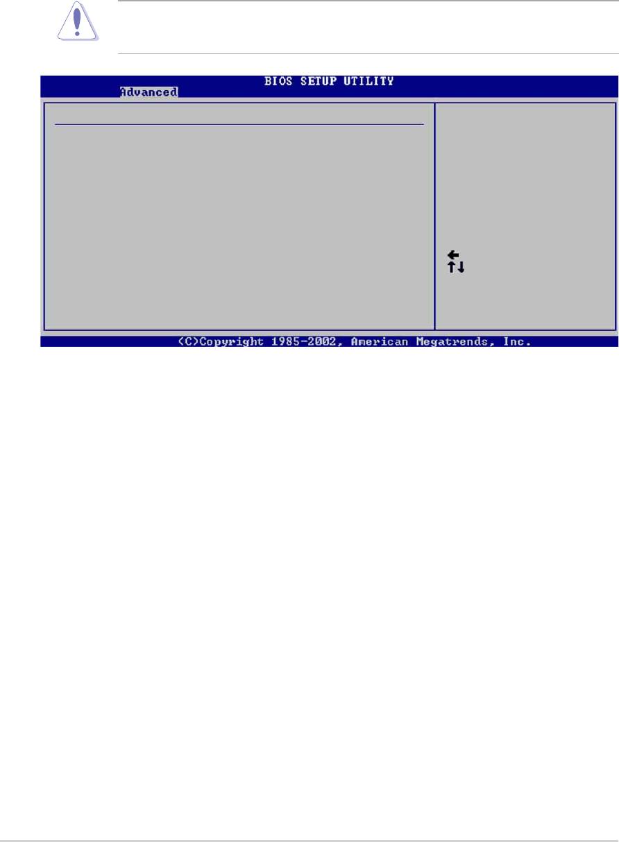
4.4.3 Chipset
The Chipset menu items allow you to change the advanced chipset
settings. Select an item then press Enter to display the sub-menu.
Advanced Chipset settings
WARNING: Setting wrong values in the sections below
may cause system to malfunction.
Configure DRAM Timing by SPD [Enabled]
Performance Acceleration Mode [Auto]
DRAM Idle Timer [Auto]
DRAm Refresh Rate [Auto]
Graphic Adapter Priority [AGP/PCI]
Graphics Aperture Size [ 64 MB]
Spread Spectrum [Enabled]
Select Screen
Select Item
ICH Delayed Transaction [Enabled]
+- Change Option
F1 General Help
MPS Revision [1.4]
F10 Save and Exit
ESC Exit
4-18
Chapter 4: BIOS Setup

Configure DRAM Timing by SPD [Enabled]
When this item is enabled, the DRAM timing parameters are set according
to the DRAM SPD (Serial Presence Detect). When disabled, you can
manually set the DRAM timing parameters through the DRAM sub-items.
Configuration options: [Disabled] [Enabled]
Performance Acceleration Mode [Auto]
This field when [Enabled] minimize latencies from CPU to memory to
boost system performance. Configuration options: [Auto] [Enabled]
Setting to [Enabled] may cause the system to become unstable! If this
happens, revert to the default setting [Auto].
DRAM Idle Timer [Auto]
Configuration options: [Infinite] [0T] [8T] [16T] [64T] [Auto]
DRAM Refresh Mode [Auto]
Configuration options: [Auto] [15.6 uSec] [7.8 uSec] [64 uSec] [64T]
If the system becomes unstable after changing the settings of any of
the above items, revert to the default settings.
The following sub-items appear only when the item Configure DRAM
Timing by SPD is set to Disabled.
DRAM CAS# Latency [2.5 Clocks]
This item controls the latency between the SDRAM read command and
the time the data actually becomes available. Configuration options:
[2.0 Clocks] [2.5 Clocks] [3.0 Clocks]
DRAM RAS# Precharge [4 Clocks]
This item controls the idle clocks after issuing a precharge command to
the DDR SDRAM. Configuration options: [4 Clocks] [3 Clocks]
[2 Clocks]
DRAM RAS# to CAS# Delay [4 Clocks]
This item controls the latency between the DDR SDRAM active
command and the read/write command. Configuration options:
[4 Clocks] [3 Clocks] [2 Clocks]
DRAM Precharge Delay [8 Clocks]
Configuration options: [8 Clocks] [7 Clocks] [6 Clocks] [5 Clocks]
DRAM Burst Length [4 Clocks]
Configuration options: [4 Clocks] [8 Clocks]
ASUS P4P800 motherboard user guide
4-19
Graphic Adapter Priority [AGP/PCI]
Allows selection of the graphics controller to use as primary boot device.
Configuration options: [AGP/PCI] [PCI/AGP]
Graphics Aperture Size [64MB]
Allows you to select the size of mapped memory for AGP graphic data.
Configuration options: [4MB] [8MB] [16MB] [32MB] [64MB] [128MB]
[256MB]
Spread Spectrum [Enabled]
This field enables or disables the clock generator spread spectrum.
Configuration options: [Disabled] [Enabled]
ICH Delayed Transaction [Enabled]
Configuration options: [Disabled] [Enabled]
MPS Revision [1.4]
Configuration options: [1.1] [1.4]
4.4.4 Onboard Devices Configuration
OnBoard AC’97 Audio [Auto]
OnBoard LAN [Enabled]
OnBoard LAN Boot ROM [Disabled]
Onboard Floppy Controller [Enabled]
Serial Port1 Address [3F8/IRQ4]
Serial Port2 Address [2F8/IRQ3]
Parallel Port Address [378]
Parallel Port Mode [ECP]
ECP Mode DMA Channel [DMA3]
Parallel Port IRQ [IRQ7]
OnBoard Game/MIDI Port [Disabled]
Select Screen
Select Item
+- Change Option
F1 General Help
F10 Save and Exit
ESC Exit
OnBoard AC’97 Audio [Auto]
[Auto] allows the BIOS to detect whether you are using any audio device.
If an audio device is detected, the onboard audio controller is enabled; if
no audio device is detected, the controller is disabled. Configuration
options: [Disabled] [Auto]
4-20
Chapter 4: BIOS Setup

OnBoard LAN [Enabled]
Allows you to enable or disable the onboard LAN controller. Configuration
options: [Disabled] [Enabled]
OnBoard LAN Boot ROM [Disabled]
Allows you to enable or disable the option ROM in the onboard LAN
controller. This item appears only when the Onboard LAN item is set to
Enabled. Configuration options: [Disabled] [Enabled]
OnBoard Floppy Controller [Enabled]
Allows you to enable or disable the floppy disk controller. Configuration
options: [Disabled] [ Enabled]
Serial Port1 Address [3F8/IRQ4]
Allows you to select the Serial Port1 base address. Configuration options:
[Disabled] [3F8/IRQ4] [3E8/IRQ4] [2E8/IRQ3]
Serial Port2 Address [2F8/IRQ3]
Allows you to select the Serial Port2 base address. Configuration options:
[Disabled] [2F8/IRQ3] [3E8/IRQ4] [2E8/IRQ3]
Parallel Port Address [378]
Allows you to select the Parallel Port base addresses. Configuration
options: [Disabled] [378] [278] [3BC]
Parallel Port Mode [ECP]
Allows you to select the Parallel Port mode. Configuration options:
[Normal] [Bi-directional] [EPP] [ECP]
ECP Mode DMA Channel [DMA3]
Configuration options: [DMA0] [DMA1] [DMA3]
Parallel Port IRQ [IRQ7]
Configuration options: [IRQ5] [IRQ7]
Onboard Game/MIDI Port [Disabled]
Allows you to select the Game Port address or to disable the port.
Configuration options: [Disabled] [200/300] [200/330] [208/300] [208/330]
ASUS P4P800 motherboard user guide
4-21
4.4.5 PCI PnP
The PCI PnP menu items allow you to change the advanced settings for
PCI/PnP devices. The menu includes setting IRQ and DMA channel
resources for either PCI/PnP or legacy ISA devices, and setting the
memory size block for legacy ISA devices.
Take caution when changing the settings of the PCI PnP menu items.
Incorrect field values may cause the system to malfunction.
Advanced PCI/PnP settings
NO: Lets the bIOS
WARNING: Setting wrong values in the sections below
configure all the
may cause system to malfunction.
devices in the system.
YES: Lets the
Plug and Play OS [No]
operating system
PCI Latency Timer [64]
configure Plug and
Allocate IRQ to PCI VGA [Yes]
Play (PnP) devices not
Palette Snooping [Disabled]
required for boot if
PCI IDE BusMaster [Enabled]
your system has a Plug
IRQ3 [Available]
and Play operating
IRQ4 [Available]
system.
IRQ5 [Available]
Select Screen
IRQ7 [Available]
Select Item
IRQ9 [Available]
+- Change Option
IRQ10 [Available]
F1 General Help
IRQ11 [Available]
F10 Save and Exit
IRQ14 [Available]
ESC Exit
IRQ15 [Available]
Plug and Play O/S [No]
When set to [No], BIOS configures all the devices in the system. When set
to [Yes] and if you installed a Plug & Play operating system, the operating
system configures the Plug & Play devices not required for boot.
Configuration options: [No] [Yes]
PCI Latency Timer [64]
Allows you to select the value in units of PCI clocks for the PCI device
latency timer register. Configuration options: [32] [64] [96] [128] [160] [192]
[224] [248]
Allocate IRQ to PCI VGA [Yes]
When set to [Yes], BIOS assigns an IRQ to PCI VGA card if the card
requests for an IRQ. When set to [No], BIOS does not assign an IRQ to
the PCI VGA card even if requested. Configuration options: [No] [Yes]
4-22
Chapter 4: BIOS Setup
Pallete Snooping [Disabled]
When set to [Enabled], the pallete snooping feature informs the PCI
devices that an ISA graphics device is installed in the system so that the
latter can function correctly. Setting to [Disabled] deactivates this feature.
Configuration options: [Disabled] [Enabled]
PCI IDE BusMaster [Enabled]
Allows BIOS to use PCI bus mastering when reading/writing to IDE
devices. Configuration options: [Disabled] [Enabled]
IRQ xx [Available]
When set to [Available], the specific IRQ is free for use of PCI/PnP
devices. When set to [Reserved], the IRQ is reserved for legacy ISA
devices. Configuration options: [Available] [Reserved]
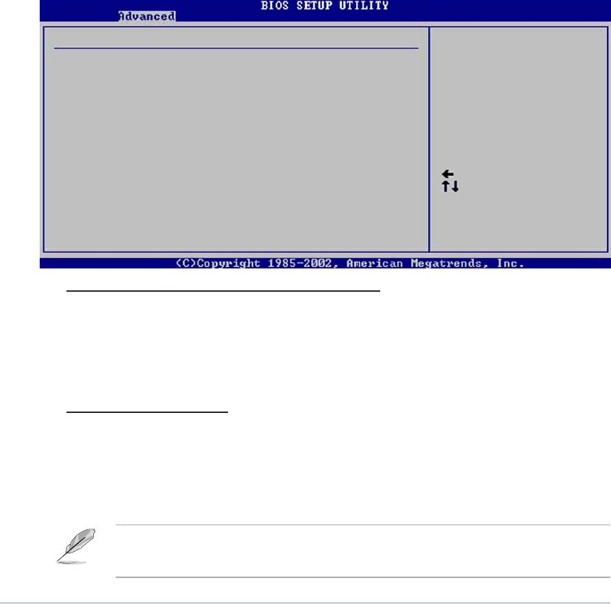
4.4.6 USB Configuration
The items in this menu allows you to change the USB-related features.
Select an item then press Enter to display the configuration options.
USB Configuration
Enables USB host
controllers.
Module Version : 2.22.4-5.3
USB Devices Enabled : None
USB Function [8 USB Ports]
Legacy USB Support [Auto]
USB 2.0 Controller [Enabled]
USB 2.0 Controller Mode [HiSpeed]
USB Mass Storage Device Configuration
Select Screen
Select Item
+- Change Option
F1 General Help
F10 Save and Exit
ESC Exit
The Module Version and USB Devices Enabled items show the auto-
detected values. If no USB device is detected, the item shows None.
USB Function [8 USB Ports]
Allows you to set the number of USB ports to activate. Configuration
options: [Disabled] [2 USB Ports] [4 USB Ports] [6 USB Ports] [8 USB
Ports]
ASUS P4P800 motherboard user guide
4-23
Legacy USB Support [Auto]
Allows you to enable or disable support for legacy USB devices. Setting to
Auto allows the system to detect the presence of USB devices at startup. If
detected, the USB controller legacy mode is enabled. If no USB device is
detected, the legacy USB support is disabled. Configuration options:
[Disabled] [Enabled] [Auto]
USB 2.0 Controller [Enabled]
Allows you to enable or disable the USB 2.0 controller. Configuration
options: [Disabled] [Enabled]
USB 2.0 Controller Mode [HiSpeed]
Allows you to configure the USB 2.0 controller in HiSpeed (480 Mbps) or
Full Speed (12 Mbps). Configuration options: [HiSpeed ] [Full Speed]
USB Mass Storage Device Configuration
USB Mass Storage Device Configuration
Number of seconds
POST waits for the USB
USB Mass Storage Reset Delay [20 Sec]
mass storage device
after that start unit
No USB Mass Storage device detected
command.
Device #1 N/A
Emulation Type [N/A]
Device #2 N/A
Emulation Type [N/A]
Device #3 N/A
Emulation Type [N/A]
Device #4 N/A
Select Screen
Emulation Type [N/A]
Select Item
Device #5 N/A
+- Change Option
Emulation Type [N/A]
F1 General Help
Device #6 N/A
F10 Save and Exit
Emulation Type [N/A]
ESC Exit
USB Mass Storage Reset Delay [20 Sec]
Allows you to select the number of seconds POST waits for the USB
mass storage device after the start unit command. The message “No
USB mass storage device detected” appears if none is installed in the
system. Configuration options: [10 Sec ] [20 Sec] [30 Sec] [40 Sec]
Emulation Type [N/A]
When set to Auto, USB devices less than 530MB will be emulated as
floppy drive, and the remaining drives as hard drives. Forced FDD
option can be used to force an HDD formatted drive to boot as FDD
(for example, ZIP drive).
The Device and Emulation Type items appear only when there are
installed USB devices.
4-24
Chapter 4: BIOS Setup

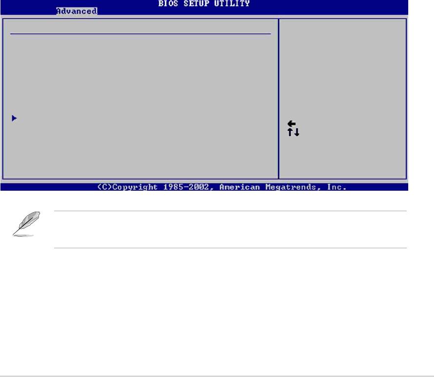
4.4.7 Instant Music Configuration
Instant Music Option
Disable/Enable Instant
Music feature.
Instant Music [Disabled]
Select Screen
Select Item
+- Change Option
F1 General Help
F10 Save and Exit
ESC Exit
Instant Music [Disabled]
Allows you to enable or disable the Instant Music feature in BIOS.
Configuration options: [Disabled] [Enabled]
When Instant Music is enabled, the PS/2 keyboard power up feature is
automatically disabled.
Instant Music CD-ROM Drive [IDE Secondary Master]
Allows you to select the CD-ROM drive that you wish to use for the Instant
Music CD playback. Configuration options: [IDE Primary Master] [IDE
Primary Slave] [IDE Secondary Master] [IDE Secondary Slave]
The above item appears only if you enabled the Instant Music item.
ASUS P4P800 motherboard user guide
4-25

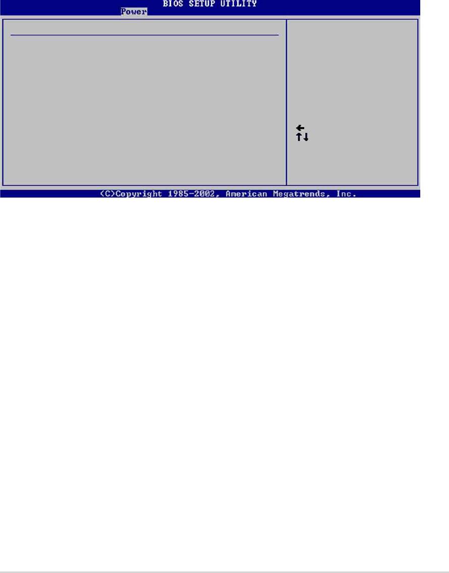
4.5 Power menu
The Power menu items allow you to change the settings for the Advanced
Power Management (APM). Select an item then press Enter to display the
configuration options.
Suspend Mode [Auto]
Configure CPU.
Repost Video on S3 Resume [No]
ACPI 2.0 Support [No]
ACPI APIC Support [Enabled]
BIOS -> AML ACPI table [Enabled]
APM Configuration
Hardware Monitor
Select Screen
Select Item
Enter Go to Sub-screen
F1 General Help
F10 Save and Exit
ESC Exit
4.5.1 Suspend Mode [Auto]
Allows you to select the ACPI state to be used for system suspend.
Configuration options: [S1 (POS) Only] [S3 Only] [Auto]
4.5.2 Repost Video on S3 Resume [No]
Determines whether to invoke VGA BIOS POST on S3/STR resume.
Configuration options: [No] [Yes]
4.5.3 ACPI 2.0 Support [No]
Allows you to add more tables for ACPI 2.0 specifications. Configuration
options: [No] [Yes]
4.5.4 ACPI APIC Support [Enabled]
Allows you to enable or disable the ACPI support in the ASIC. When set to
Enabled, the ACPI APIC table pointer is included in the RSDT pointer list.
Configuration options: [Disabled] [Enabled]
4.5.5 BIOS -> AML ACPI Table [Enabled]
Allows you to enable or disable the inclusion of the BIOS ->AML exchange
pointer to (X)RSDT pointer list. Configuration options: [Disabled] [Enabled]
4-26
Chapter 4: BIOS Setup

4.5.6 APM Configuration
APM Configuration
Enabled or disable
Power Management/APM [Enabled]
APM.
Video Power Down Mode [Suspend]
Hard Disk Power Down Mode [Suspend]
Suspend Time Out [Disabled]
Throttle Slow Clock Ratio [50%]
System Thermal [Disabled]
Power Button Mode [On/Off]
Restore on AC Power Loss [Power Off]
Select Screen
Power On By RTC Alarm [Disabled]
Select Item
Power On By External Modem [Disabled]
+- Change Option
Power On By PCI Devices [Disabled]
F1 General Help
Power On By PS/2 Keyboard [Disabled]
F10 Save and Exit
Power On By PS/2 Mouse [Disabled]
ESC Exit
Power Management/APM [Enabled]
Allows you to enable or disable the Advanced Power Management (APM)
feature. Configuration options: [Disbaled] [Enabled]
Video Power Down Mode [Suspend]
Allows you to select the video power down mode. Configuration options:
[Disabled] [Standby] [Suspend]
Hard Disk Power Down Mode [Suspend]
Allows you to select the hard disk power down mode. Configuration
options: [Disabled] [Standby] [Suspend]
Suspend Time Out [Disabled]
Allows you to select the specified time at which the system goes on
suspend. Configuration options: [Disabled] [1-2 Min] [2-3 Min] [4-5 Min]
[8-9 Min] [10 Min] [20 Min] [30 Min] [40 Min] [50 Min] [60 Min]
Throttle Slow Clock Ratio [50%]
Allows you to select the duty cycle in throttle mode. Configuration options:
[87.5%] [75.0%] [62.5%] [50%] [37.5%] [25%] [12.5%]
System Thermal [Disabled]
Allows you to enable or disable the system thermal feature to generate a
power management event. Configuration options: [Disabled] [Enabled]
ASUS P4P800 motherboard user guide
4-27

Power Button Mode [On/Off]
Allows the system to go into On/Off mode or suspend mode when the
power button is pressed. Configuration options: [On/Off] [Suspend]
Restore on AC Power Loss [Power Off]
When set to Power Off, the system goes into off state after an AC power
loss. When set to Power On, the system goes on after an AC power loss.
When set to Last State, the system goes into either off or on state
whatever was the system state before the AC power loss. Configuration
options: [Power Off] [Power On] [Last State]
Power On By RTC Alarm [Disabled]
Allows you to enable or disable RTC to generate a wake event. When this
item is set to Enabled, the items RTC Alarm Date, RTC Alarm Hour, RTC
Alarm Minute, and RTC Alarm Second appear with set values.
Configuration options: [Disabled] [Enabled]
Power On By External Modem [Disabled]
This allows either settings of [Enabled] or [Disabled] for powering up the
computer when the external modem receives a call while the computer is
in Soft-off mode. Configuration options: [Disabled] [Enabled]
The computer cannot receive or transmit data until the computer and
applications are fully running. Thus, connection cannot be made on the
first try. Turning an external modem off and then back on while the
computer is off causes an initialization string that turns the system
power on.
Power On By PCI Devices [Disabled]
When set to [Enabled], this parameter allows you to turn on the system
through a PCI LAN or modem card. This feature requires an ATX power
supply that provides at least 1A on the +5VSB lead.
Configuration options: [Disabled] [Enabled]
Power On By PS/2 Keyboard [Disabled]
This parameter allows you to use specific keys on the keyboard to turn on
the system. This feature requires an ATX power supply that provides at
least 1A on the +5VSB lead. Configuration options: [Disabled] [Enabled]
4-28
Chapter 4: BIOS Setup
Power On By PS/2 Mouse [Disabled]
When set to [Enabled], this parameter allows you to use the PS/2 mouse
to turn on the system. This feature requires an ATX power supply that
provides at least 1A on the +5VSB lead. Configuration options: [Disabled]
[Enabled]
4.5.7 Hardware Monitor
Hardware Monitor
CPU temperature
CPU Temperature [44°C/111°F]
MB Temperature [36°C/96.5°F]
Power Temperature [N/A]
Q-Fan Control [Disabled]
CPU Fan Speed [2250RPM]
Chassis Fan Speed [XXX RPM]
Power Fan Speed [XXX RPM]
Select Screen
VCORE Voltage [1.550V]
Select Item
3.3V Voltage [3.386V]
+- Change Option
5V Voltage [4.890V]
F1 General Help
12V Voltage [11.900V]
F10 Save and Exit
ESC Exit
MB Temperature [xxxC/xxxF]
CPU Temperature [xxxC/xxxF]
POWER Temperature [N/A]
The onboard hardware monitor automatically detects and displays the
motherboard, CPU, and power supply temperatures. Select Disabled if you
do not wish to display the detected temperatures.
Q-Fan Control [Disabled]
This item allows you to enable or disable the ASUS Q-Fan feature that
smartly adjusts the fan speeds for more efficient system operation. When
this field is set to [Enabled], the Fan Speed Ratio item appears to allow
selection of the appropriate fan speed ratio. Configuration options:
[Disabled] [Enabled]
ASUS P4P800 motherboard user guide
4-29

Fan Speed Ratio [11/16]
This item allows you to select the appropriate fan speed ratio for the
system. The default [11/16] is the minimum fan speed ratio. Select a
higher ratio if you installed additional devices and the system requires
more ventilation. Configuration options: [11/16] [12/16] [13/16] [14/16]
[15/16]
The above item appears only when the Q-Fan Control item is set to
Enabled.
CPU Fan Speed [xxxxRPM] or [N/A]
Chassis Fan Speed [xxxxRPM] or [N/A]
Power Fan Speed [xxxxRPM] or [N/A]
The onboard hardware monitor automatically detects and displays the
CPU, chassis, and power fan speeds in rotations per minute (RPM). If any
of the fans is not connected to the motherboard, the specific field shows
N/A.
VCORE Voltage, +3.3V Voltage, +5V Voltage, +12V Voltage
The onboard hardware monitor automatically detects the voltage output
through the onboard voltage regulators.
If any of the monitored items is out of range, the following error
message appears: “Hardware Monitor found an error. Enter Power
setup menu for details”. You will then be prompted to “Press F1 to
continue or DEL to enter SETUP”.
4-30
Chapter 4: BIOS Setup
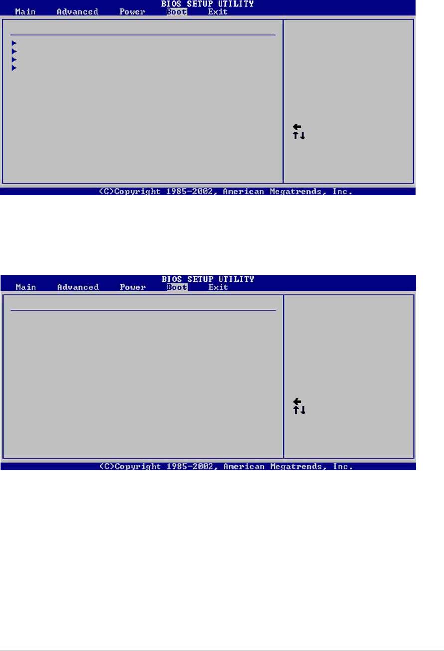
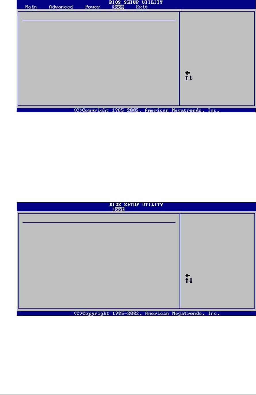
4.6 Boot menu
The Boot menu items allow you to change the system boot options. Select
an item then press Enter to display the sub-menu.
Boot Settings
Specifies the Boot
Device Priority
Boot Device Priority
sequence.
Hard Disk Drives
Boot Settings Configuration
Security
Select Screen
Select Item
Enter Go to Sub-screen
F1 General Help
F10 Save and Exit
ESC Exit
4.6.1 Boot Device Priority
Boot Device Priority
Specifies the boot
sequence from the
1st Boot Device [1st FLOPPY DRIV]
available devices.
2nd Boot Device [PM-ST320413A]
3rd Boot Device [PS-ASUS CD-S340]
A device enclosed in
parenthesis has been
disabled in the
corresponding type
menu.
Select Screen
Select Item
+- Change Option
F1 General Help
F10 Save and Exit
ESC Exit
1st ~ xxth Boot Device [1st Floppy Drive]
These items specify the boot device priority sequence from the available
devices. The number of device items that appear on the screen depends
on the the number of devices installed in the system. Configuration
options: [xxxxx Drive] [Disabled]
ASUS P4P800 motherboard user guide
4-31
4.6.2 Hard disk drives
Boot Device Priority
Specifies the boot
sequence from the
1st Boot Device [PM-ST320413A]
available devices.
2nd Boot Device [PS-ASUS CD-S340]
A device enclosed in
parenthesis has been
disabled in the
corresponding type
menu.
Select Screen
Select Item
+- Change Option
F1 General Help
F10 Save and Exit
ESC Exit
1st ~ xxth Boot Device [(Hard disk drive model name)]
These items specify the boot device priority sequence from the available
hard disk drives. The number of items that appear on the screen depends
on the the number of hard disk drives installed in the system.
Configuration options: [xxxxx Drive] [Disabled]
4.6.3 Boot Settings Configuration
Boot Settings Configuration
Allows BIOS to skip
certain tests while
Quick Boot [Enabled]
booting. This will
Full Screen Logo [Enabled]
decrease the time
Add On ROM Display Mode [Force BIOS]
needed to boot the
Bootup Num-Lock [On]
system.
PS/2 Mouse Support [Auto]
Typematic Rate [Fast]
Parity Check [Disabled]
Boot to OS/2 [No]
Wait for ‘F1’ If Error [Enabled]
Hit ‘DEL’ Message Display [Enabled]
Interrupt 19 Capture [Disabled]
Select Screen
Select Item
+- Change Option
F1 General Help
F10 Save and Exit
ESC Exit
Quick Boot [Enabled]
Enabling this item allows BIOS to skip some power on self tests (POST)
while booting to decrease the time needed to boot the system. When set
to [Disabled], BIOS performs all the POST items. Configuration options:
[Disabled] [Enabled]
4-32
Chapter 4: BIOS Setup

Full Screen Logo Enabled]
This allows you to enable or disable the full screen logo display feature.
Make sure this item is enable when using the ASUS MyLogo2™ feature.
Configuration options: [Disabled] [Enabled]
Add On ROM Display Mode [Force BIOS]
Sets the display mode for option ROM. Configuration options: [Force
BIOS] [Keep Current]
Bootup Num-Lock [On]
Allows you to select the power-on state for the NumLock. Configuration
options: [Off] [On]
PS/2 Mouse Support [Auto]
Allows you to enable or disable support for PS/2 mouse. Configuration
options: [Disabled] [Enabled] [Auto]
Typematic Rate [Fast]
Allows you to select the keyboard typematic rate. Configuration options:
[Slow] [Fast]
Parity Check [Disabled]
Allows you to enable or disable the memory parity error checking.
Configuration options: [Disabled] [Enabled]
Boot to OS/2 [No]
Allows you to specify the OS/2 compatibility mode. Configuration options:
[No] [Yes]
Wait for ‘F1’ If Error [Enabled]
When set to Enabled, the system waits for F1 key to be pressed when
error occurs. Configuration options: [Disabled] [Enabled]
Hit ‘DEL’ Message Display [Enabled]
When set to Enabled, the system displays the message “Press DEL to run
Setup” during POST. Configuration options: [Disabled] [Enabled]
Interrupt 19 Capture [Disabled]
When set to [Enabled], this function allows the option ROMs to trap
Interrupt 19. Configuration options: [Disabled] [Enabled]
ASUS P4P800 motherboard user guide
4-33

4.6.4 Security
The Security menu items allow you to change the system security settings.
Select an item then press Enter to display the configuration options.
Security Settings
<Enter> to change
password.
Supervisor Password Not Installed
<Enter> again to
User Password Not Installed
disable password.
Change Supervisor Password
Boot Sector Virus Protection [Disabled]
Select Screen
Select Item
+- Change Option
F1 General Help
F10 Save and Exit
ESC Exit
Change Supervisor Password
Select this item to set or change the supervisor password. The Supervisor
Password item on top of the screen shows the default Not Installed. After
you have set a password, this item shows Installed.
To set a Supervisor Password:
1. Select the Change Supervisor Password item and press Enter.
2. On the password box that appears, type a password composed of
letters and/or numbers, then press Enter. Your password should have
at least six characters.
3. Confirm the password when prompted.
The message “Password Installed” appears after you have
successfully set your password.
The Supervisor Password item now shows Installed.
To change the supervisor password, follow the same steps as in setting a
user password.
To clear the supervisor password, select the Change Supervisor Password
then press Enter. The message “Password Uninstalled” appears.
If you forget your BIOS password, you can clear clear it by erasing the
CMOS Real Time Clock (RTC) RAM. See section “2.7 Jumpers” for
information on how to erase the RTC RAM.
4-34
Chapter 4: BIOS Setup

After you have set a supervisor password, the other items appear to allow
you to change other security settings.
Security Settings
<Enter> to change
password.
Supervisor Password Installed
<Enter> again to
User Password Not Installed
disable password.
Change Supervisor Password
User Access Level [Full Access]
Change User Password
Clear User Password
Password Check [Setup]
Boot Sector Virus Protection [Disabled]
Select Screen
Select Item
+- Change Option
F1 General Help
F10 Save and Exit
ESC Exit
User Access Level (Full Access]
This item allows you to select the access restriction to the Setup items.
Configuration options: [No Access] [View Only] [Limited] [Full Access]
No Access prevents user access to the Setup utility.
View Only allows access but does not allow change to any field.
Limited allows change to only selected fields, such as Date and Time.
Full Access allows viewing and changing all the fields in the Setup
utility.
Change User Password
Select this item to set or change the user password. The User Password
item on top of the screen shows the default Not Installed. After you have
set a password, this item shows Installed.
To set a User Password:
1. Select the Change User Password item and press Enter.
2. On the password box that appears, type a password composed of
letters and/or numbers, then press Enter. Your password should have
at least six characters.
3. Confirm the password when prompted.
The message “Password Installed” appears after you have
successfully set your password.
The User Password item now shows Installed.
ASUS P4P800 motherboard user guide
4-35
To change the user password, follow the same steps as in setting a user
password.
Clear User Password
Select this item if you wish to clear the user password.
Password Check [Setup]
When set to [Setup], BIOS checks for user password when accessing the
Setup utility. When set to [Always], BIOS checks for user password both
when accessing Setup and booting the system. Configuration options:
[Setup] [Always]
Boot Sector Virus Protection [Disabled]
Allows you to enable or disable the boot sector virus protection.
Configuration options: [Disabledc] [Enabled]
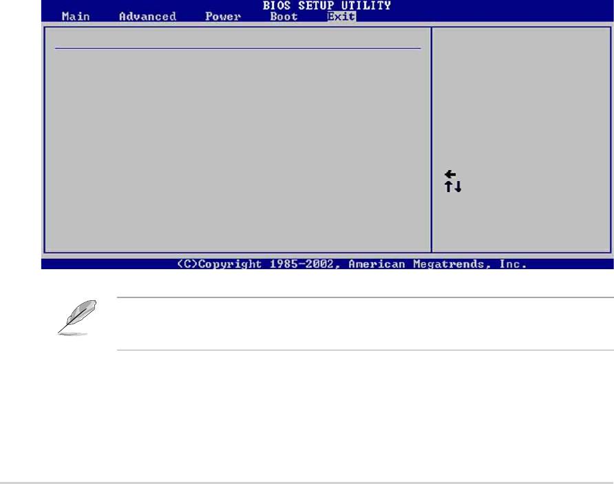
4.7 Exit menu
The Exit menu items allow you to load the optimal or failsafe default values
for the BIOS items, and save or discard your changes to the BIOS items.
Exit Options
Exit system setup
after saving the
Exit & Save Changes
changes.
Exit & Discard Changes
Discard Changes
F10 key can be used
for this operation.
Load Setup Defaults
Select Screen
Select Item
Enter Go to Sub-screen
F1 General Help
F10 Save and Exit
ESC Exit
Pressing <Esc> does not immediately exit this menu. Select one of the
options from this menu or <F10> from the legend bar to exit.
4-36
Chapter 4: BIOS Setup

Exit & Save Changes
Once you are finished making your selections, choose this option from the
Exit menu to ensure the values you selected are saved to the CMOS RAM.
The CMOS RAM is sustained by an onboard backup battery and stays on
even when the PC is turned off. When you select this option, a
confirmation window appears. Select [Yes] to save changes and exit.
If you attempt to exit the Setup program without saving your changes,
the program prompts you with a message asking if you want to save
your changes before exiting. Pressing <Enter> saves the changes
while exiting.
Exit & Discard Changes
Select this option only if you do not want to save the changes that you
made to the Setup program. If you made changes to fields other than
system date, system time, and password, the BIOS asks for a confirmation
before exiting.
Discard Changes
This option allows you to discard the selections you made and restore the
previously saved values. After selecting this option, a confirmation
appears. Select [Yes] to discard any changes and load the previously
saved values.
Load Setup Defaults
This option allows you to load the default values for each of the
parameters on the Setup menus. When you select this option or if you
press <F5>, a confirmation window appears. Select [Yes] to load default
values. Select Exit Saving Changes or make other changes before saving
the values to the non-volatile RAM.
ASUS P4P800 motherboard user guide
4-37

4-38
Chapter 4: BIOS Setup
