Asus A7N8X: Chapter 2
Chapter 2: Asus A7N8X
Chapter 2
Hardware information

ASUS A7N266-VM motherboard
2.1 Motherboard installation
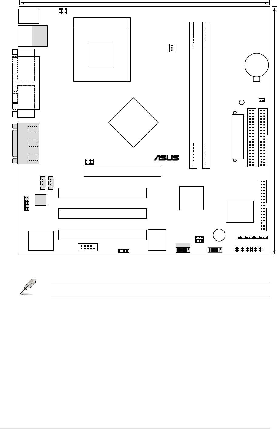
The A7N266-VM uses the Micro-ATX form factor, measuring 24.5 cm
(9.6 in.) x 24.5 cm (9.6 in.) - a standard fit for most large chassis.
WARNING! Unplug the power cord before installing the motherboard.
Failure to do so may cause you physical injury and damage motherboard
components.
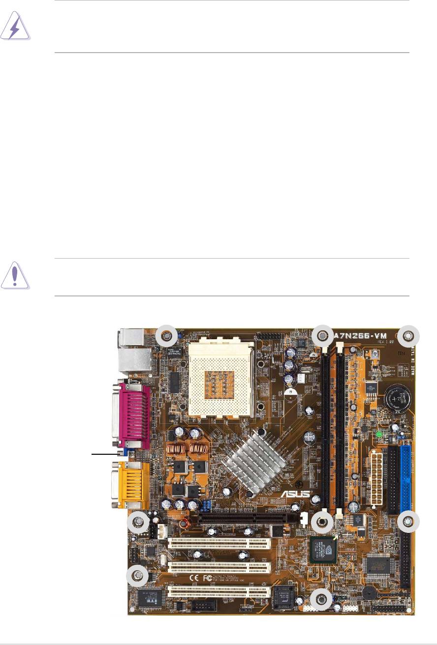
2.1.1 Placement direction
When installing the motherboard, take care to orient the chassis correctly:
The edge with external ports goes to the rear part of the chassis. Refer to the
image below. It may be more convenient to install major cables, the CPU
and modular components before fixing the motherboard inside the case frame.
2.1.2 Screw holes
Place eight (8) screws into the holes indicated by circles to secure the
motherboard to the chassis.
CAUTION! Do not overtighten the screws! Doing so may damage the
motherboard.
Place this side towards
the rear of the chassis
ASUS A7N266-VM motherboard user guide
7
24.5cm (9.64in)
USBPWR01
A7N266-VM
PS/2
KBPWR1
T: Mouse
B: Keyboard
Socket 462
Bottom:
Top:
USB1
RJ-45
USB2
COM1
CPU_FAN
CR2032 3V
Lithium Cell
CMOS Power
PARALLEL PORT
CLRTC
PLED
Primary IDE
VGA
nVidia
220D
Line
Out
Chipset
Line
DDR DIMM1 (64/72 bit, 184-pin module)
DDR DIMM2 (64/72 bit, 184-pin module)
In
30.5cm (12.0in)
Mic
®
ATX Power Connector
GAME_AUDIO
In
BSEL0
BSEL1
0 1
2 3
Accelerated Graphics Port
CD_IN1
AUDIO_COM1
(AGP)
Secondary IDE
PCI 1
nVidia
FLOPPY
Audio
MCP-D
Codec
Chipset
ASUS
ASIC
AAPANEL1
PCI 2
with Hardware
Monitor
BUZZER
USBPWR23
USBPWR45
SMB
IR
PCI 3
Super
2Mb
I/O
BIOS
USB45
USB23
PANEL
COM2
SPDIF1
IDELED
Optional components are grayed in the above motherboard layout.
8
Chapter 2: Hardware information

2.2 Layout contents
CPU, Memory and Expansion Slots
1) Socket 462 p. 12 CPU Support
2) DIMM 1/2 p. 14 System Memory Support
3) PCI 1/2/3 p. 18 32-bit PCI Bus Expansion Slots
4) AGP 4x p. 18 Accelerated Graphics Slot
Motherboard Settings (Switches and Jumpers)
1) BSEL0, BSEL1 p. 19 CPU:DRAM Frequency Setting (Various)
2) KBPWR p. 20 Keyboard Wake Up (+5V / +5VSB)
3)
USBPWR_01,_23,_45
p. 21 USB Device Wake-up (Disable/Enable)
4) CLRTC p. 22 Clear RTC RAM (CLRTC)
Connectors
1) PS2KBMS p. 23 PS/2 Mouse Port (6 pin female)
2) PS2KBMS p. 23 PS/2 Keyboard Port (6 pin female)
3) USB p. 24 Universal Serial Bus Ports 0, 1
(Two x 4 pin female)
4) COM1 / COM2 p. 24 Serial Ports (One 9-pin, One 10-1 pin)
5) VGA p. 25 Monitor Output Connector (Blue 15-pin)
6) PRINTER p. 25 Parallel Port (25 pin female)
7) GAME_AUDIO p. 25 Game/MIDI Ports (Gold 15-pin) (Optional)
8) AUDIO p. 26 Audio Connectors (Three 1/8” AUDIO) (Optional)
9) IDELED p. 26 IDE Activity LED (Two 40-1 pin)
10) FLOPPY p. 27 Floppy Disk Drive Connector (34-1 pin)
11) PRIMARY / SEC. IDE p. 27 IDE Connectors (Two 40-1 pin)
12) CPU_FAN p. 28
CPU Fan Connector (3 pin)
13) AAPANEL p. 28 ASUS Front Panel Audio Connector (10 pin)
14) ATXPWR p. 29 ATX Power Supply Connector (20 pin)
15) SMB p. 29 SMBus Connector (6-1 pin)
16)
CD_IN1, AUX
p. 30 Internal Audio Connectors (Two 4 pin)
(Optional)
17) SPDIF1 p. 30 Digital Audio Interfaces (4-1 pin SPDIF1)
(Optional)
18) USB_23, _45 p. 31 USB Headers (Two 10-1 pin)
18) IR p. 31 Infrared module connector (Two 5-1 pin)
20) PWR_LED (Panel) p. 32
System Power LED Lead (3-1 pin)
21) KEYLOCK (Panel) p. 32 Keyboard Lock Switch Lead (2 pin)
22) SPEAKER (Panel) p. 32 System Warning Speaker Lead (4 pin )
23) LED (Panel) p. 32 System Message LED Lead (2 pin)
24) SMI (Panel) p. 32 System Management Interrupt Lead (2 pin)
25) PWR (Panel) p. 32 ATX Power Switch / Soft-Off Switch Lead (2 pin)
26) RESET (Panel) p. 32 Reset Switch Lead (2 pin)
ASUS A7N266-VM motherboard user guide
9
2.3 Before you proceed
Take note of the following precautions before you install motherboard
components or change any motherboard settings.
CAUTION!
1. Unplug the power cord from the wall socket before touching any
component.
2. Use a grounded wrist strap or touch a safely grounded object or to a
metal object, such as the power supply case, before handling
components to avoid damaging them due to static electricity.
3. Hold components by the edges and do not to touch the ICs on them.
4. Whenever you uninstall any component, place it on a grounded
antistatic pad or in the bag that came with the component.
5. Before you install or remove any component, ensure that the
ATX power supply is switched off or the power cord is detached
from the power supply. Failure to do so may cause severe damage
to the motherboard, peripherals, and/or components.
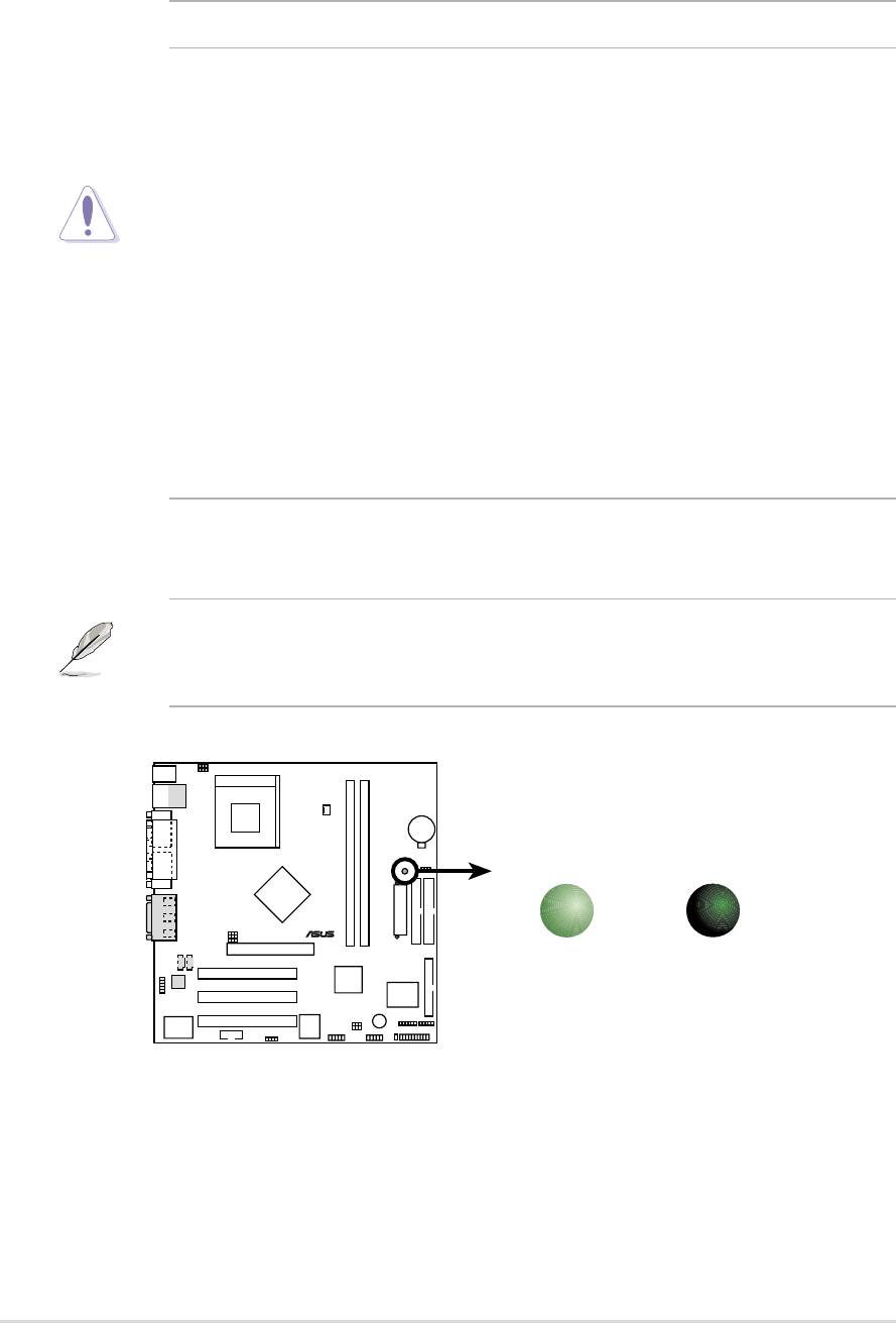
NOTE! When lit, the onboard LED indicates that the system is ON, in
sleep mode or in soft-off mode, not powered OFF. See the illustration
below.
A7N266-VM
PLED
®
ON
OFF
Standby
Powered
Power
Off
A7N266-VM Onboard LED
10
Chapter 2: Hardware information
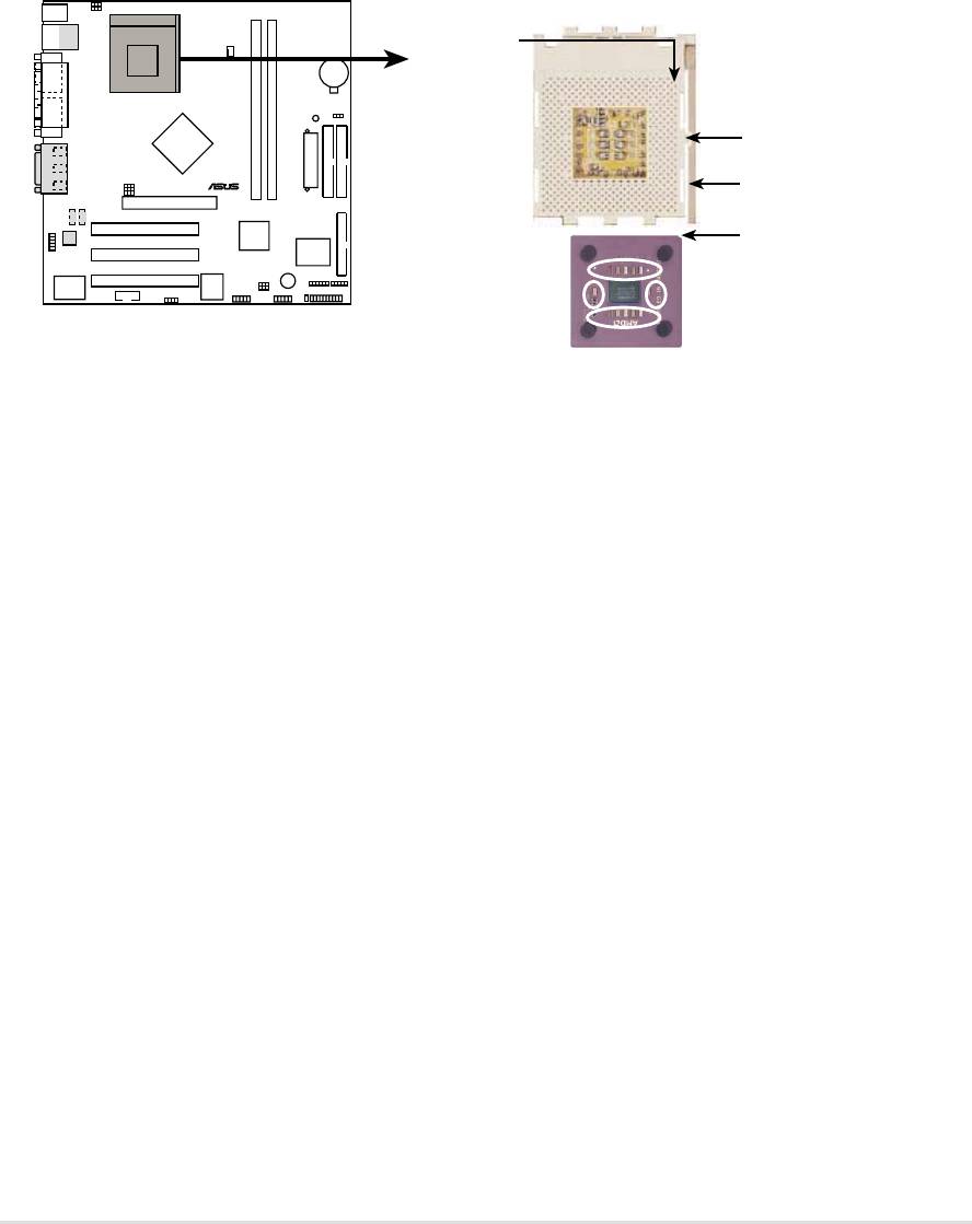
2.4 Central Processing Unit (CPU)
2.4.1 Overview
The motherboard provides a Socket A (462) for CPU installation. AMD
processors offer gigahertz speeds to support all the latest computing platforms
™
and applications. The A7N266-VM supports Athlon
XP processors with
“QuantiSpeed” data processing, large data caches, 3D enhancements and
266Mhz bus speeds.
A7N266-VM
CPU NOTCH
TO INNER
CORNER
LOCK
®
LEVER
CPU NOTCH
AMD™ CPU
A7N266-VM Socket 462
Each AMD CPU has a “marked” corner. This corner is usually indicated with
a notch, and/or a golden square or triangle. Refer to this indicator while
orienting the CPU. See the next page for installation details.
A fan and heatsink should be attached to the CPU to prevent overheating.
ASUS A7N266-VM motherboard user guide
11
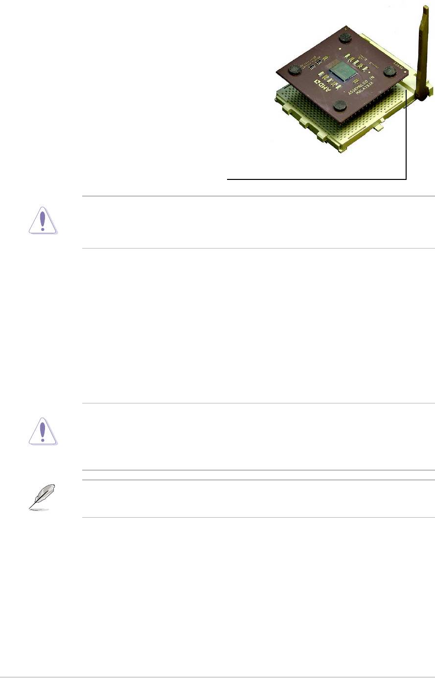
2.4.2 Installing the CPU
Follow these steps to install a CPU:
1. Locate the Socket 462 and open it by
pulling the lever gently sideways away
from the socket. Then lift the lever
upwards. The socket lever must be fully
opened (90 to 100 degrees).
2. Insert the CPU with the correct
orientation. The notched or golden
corner of the CPU must be oriented
toward the inner corner of the socket
base nearest to the lever hinge.
CAUTION! The CPU should drop easily into place. Do not force the
CPU into the socket to avoid bending the pins. If the CPU does not fit,
check its alignment and look for bent pins.
4. Once completely inserted, press the CPU firmly and close the socket
lever until it snaps shut.
5. Place the CPU fan and heatsink on the CPU. The heatsink should entirely
cover the CPU. Carefully attach the heatsink locking brace to the plastic
clips on the socket base. With the added weight of the CPU fan and
heatsink locking brace, no extra force is required to keep the CPU in
place
CAUTION! Take care not to scrape the motherboard surface when
mounting a clamp-style processor fan, or else damage may occur. When
mounting a heatsink onto your CPU, make sure that exposed CPU
capacitors do not touch the heatsink, or damage may occur!
NOTE! Do not neglect to set the correct Bus Frequency and leave the
CPU Multiple setting at default to avoid start-up problems.
12
Chapter 2: Hardware information
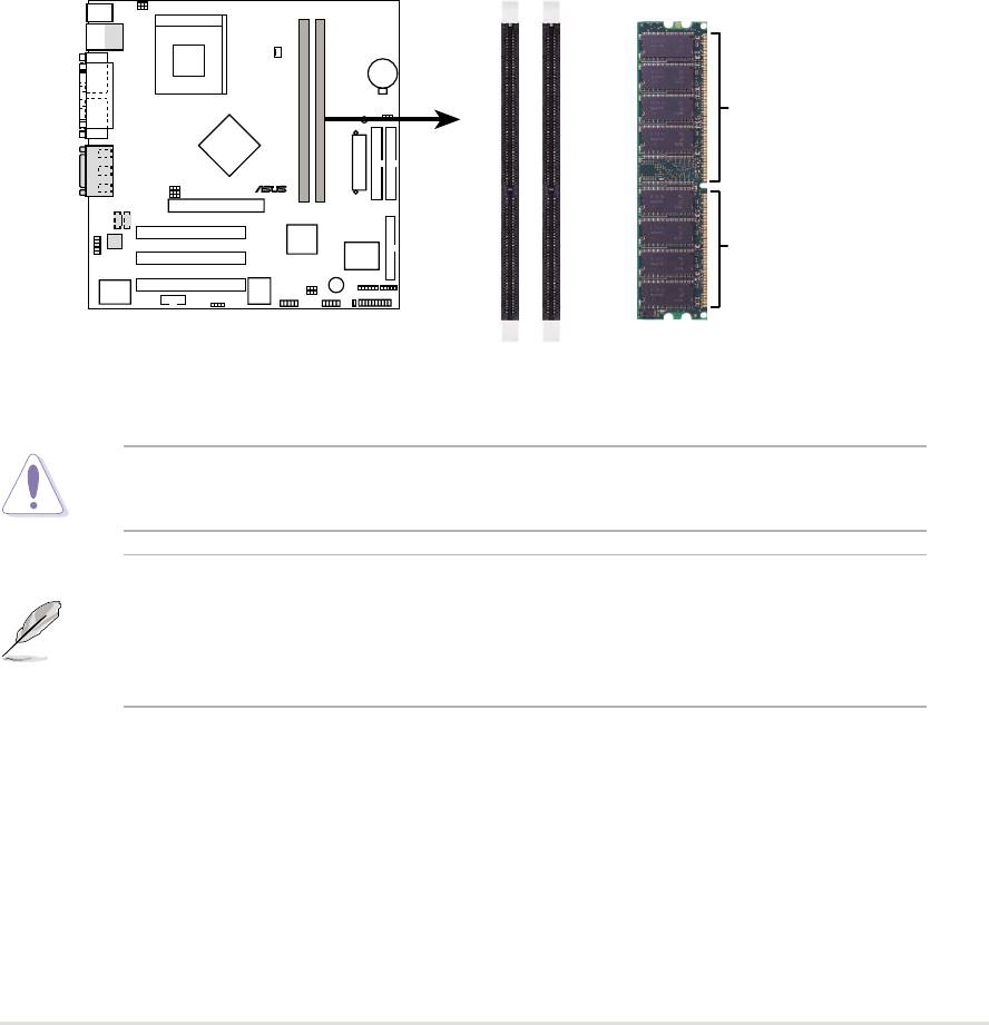
2.5 System memory
2.5.1 Overview
This motherboard uses only Double Data Rate (DDR) Synchronous Dynamic
Random Access Memory (SDRAM) Dual Inline Memory Modules (DIMMs).
These sockets support up to 1GB system memory using non-ECC PC200/
266 DIMMs.
Each DIMM socket/module is two-sided: each side defines one “row” of
memory. DIMMs come in combinations of single or double-sided types
ranging through 64MB, 128MB, 256MB, 512MB
to form a total memory size of 64MB to 1GB.
~ Two (2) sockets are available for both 266MHz-PC2100 or 200MHz-PC1600
DDR DIMMs to form a memory size of 64MB to 1GB.
A7N266-VM
104 Pins
®
80 Pins
A7N266-VM 184-Pin DDR
DIMM Sockets
CAUTION! DIMMs are keyed to fit into notches with only one direction.
DO NOT force a DIMM into a socket to avoid damaging the DIMM.
• DIMMs with more than 18 chips are not supported.
• ASUS motherboards support SPD (Serial Presence Detect)DIMMs.
This is the memory of choice for best performance vs. stability
• BIOS shows DDR SDRAM memory on bootup screen.
ASUS A7N266-VM motherboard user guide
13
2.5.2 Memory configurations
Install DIMMs in any of the following combinations.
DIMM Location 184-pin DIMM (DDR) Total Memory
Socket 1 (Rows 0&1) 64MB, 128MB, 256MB, 512MB x1
Socket 2 (Rows 2&3) 64MB, 128MB, 256MB, 512MB x1
Total system memory (Max. 1GB) =
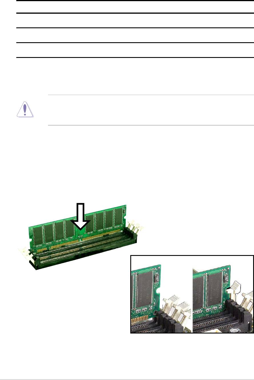
2.5.3 Installing a DIMM
CAUTION! Make sure to unplug the power supply before adding or
removing DIMMs or other system components. Failure to do so may cause
severe damage to both the motherboard and the components.
Installing a DIMM:
1. Unlock a DIMM socket by pressing the retaining clips outward.
2. Align a DIMM on the socket such that the notches on the DIMM exactly
match the notches in the socket.
3. Firmly insert the DIMM into the socket until the retaining clips snap back
in place.
Unlocked Retaining Clip Locked Retaining Clip
14
Chapter 2: Hardware information
2.6 Expansion slots
The motherboard has three PCI slots and one Accelerated Graphics Port
(AGP) slot.. The following sub-sections describe the slots and the expansion
cards that they support.
WARNING! Unplug your power supply when adding or removing
expansion cards or other system components. Failure to do so may cause
you physical injury and damage motherboard components.
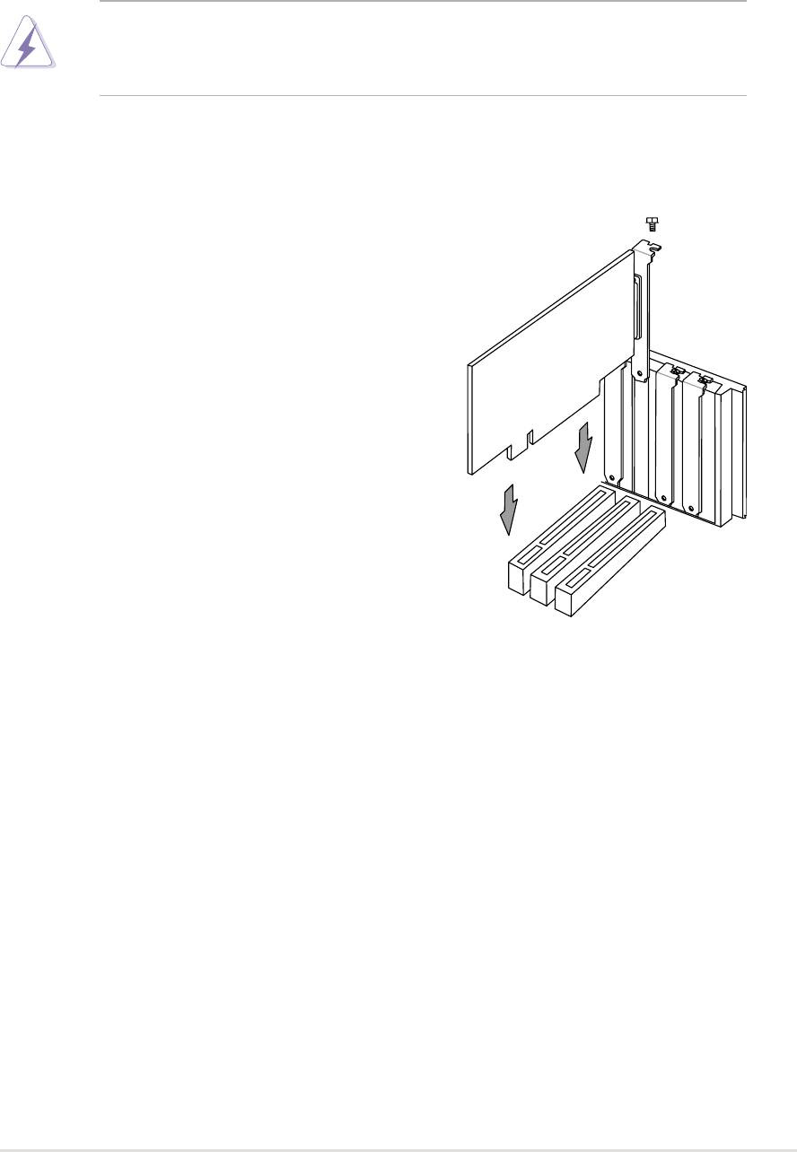
2.6.1 Installing an expansion card
Follow these steps to install an expansion
card.
1. Before installing the expansion card, read
the documentation that came with it and
make the necessary hardware settings.
2. Remove the system unit cover (if your
motherboard is already installed in a
chassis).
3. Remove the bracket opposite the PCI slot.
Keep the screw for later use.
4. Align the card connector with the slot and
press firmly until the card is completely
seated on the slot.
5. Secure the card to the chassis with the
screw you removed earlier.
6. Replace the system cover.
7. Set up the BIOS if necessary.
8. Install the necessary software drivers for your expansion card.
ASUS A7N266-VM motherboard user guide
15
2.6.2 Configuring an expansion card
Some expansion cards need an IRQ to operate. Generally, an IRQ must be
exclusively assigned to one function at a time. In a standard design
configuration, 16 IRQs are available but most are already in use. Normally,
6 IRQs are free for expansion cards. If the motherboard has PCI audio
onboard, an additional IRQ will be used. If your motherboard also has MIDI
enabled, another IRQ will be used, leaving 4 IRQs free. Sometimes IRQs
are “shared” by more than one function; in this case, IRQ assignments are
swapped automatically or adjusted through the BIOS firmware.
IMPORTANT! When using PCI cards on shared slots, ensure that the
drivers support “Share IRQ” or that the cards do not need IRQ
assignments. Otherwise, conflicts will arise between the three PCI groups,
making the system unstable and the card inoperative.
Standard Interrupt Assignments
IRQ Priority Standard Function
0 1 System Timer
1 2 Keyboard Controller
2 N/A Programmable Interrupt
3* 11 Communications Port (COM2)
4* 12 Communications Port (COM1)
5* 13 Sound Card (sometimes LPT2)
6 14 Floppy Disk Controller
7* 15 Printer Port (LPT1)
8 3 System CMOS/Real Time Clock
9* 4 ACPI Mode when used
10* 5 IRQ Holder for PCI Steering
11* 6 IRQ Holder for PCI Steering
12* 7 PS/2 Compatible Mouse Port
13 8 Numeric Data Processor
14* 9 Primary IDE Channel
15* 10 Secondary IDE Channel
*These IRQs are usually available for ISA or PCI devices.
16
Chapter 2: Hardware information
Interrupt Request Table for this Motherboard
INT-A INT-B INT-C INT-D INT-E INT-F INT-G INT-H INT-I
PCI slot 1 used ————————
PCI slot 2 ———used —————
PCI slot 3 ——used ——————
Onboard USB0 —————shared ———
Onboard USB1 —————shared ——used
Onboard Audio ————used ————
Onboard Modem———————used —
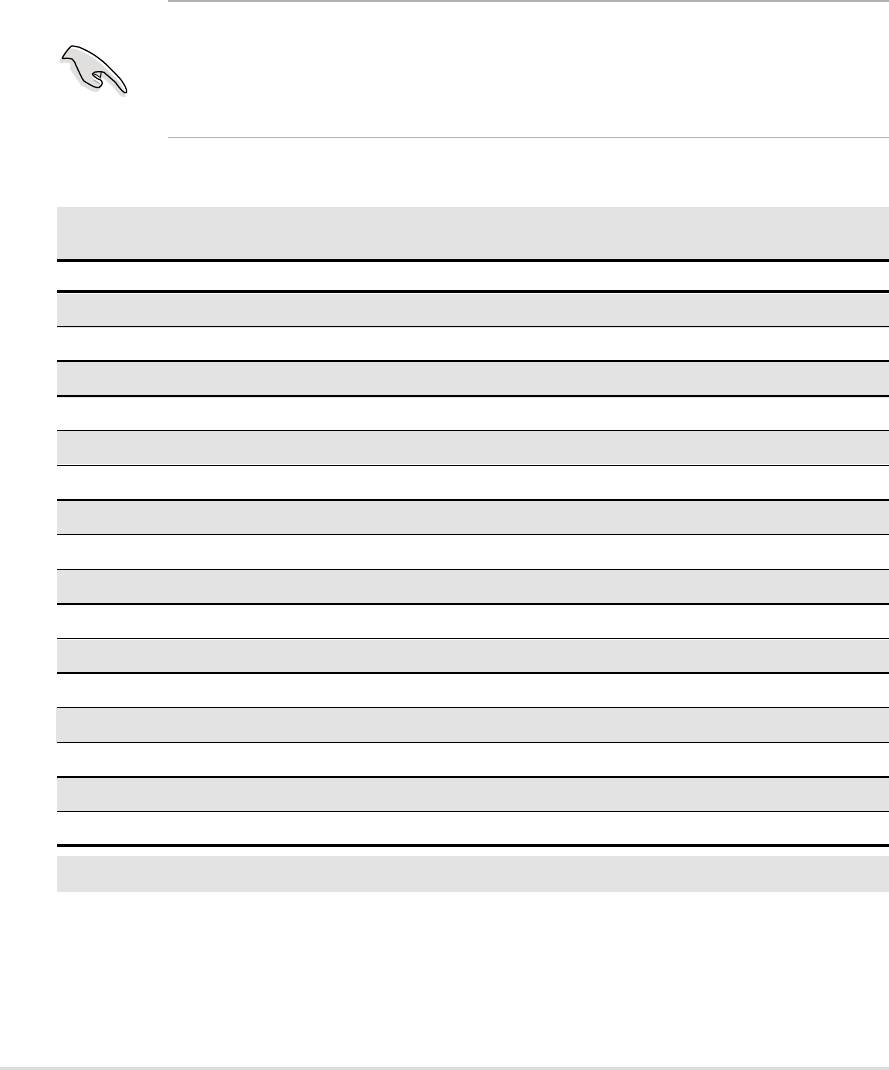
2.6.3 PCI slots
Three 32-bit PCI slots are available on this motherboard. The slots support
PCI cards such as a LAN card, SCSI card, USB card, and other cards that
comply with PCI specifications.
This figure shows a typical PCI card installed into a slot:
ASUS A7N266-VM motherboard user guide
17
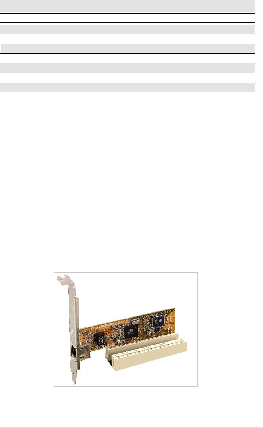
2.6.4 AGP slot
This motherboard provides an Accelerated Graphics Port (AGP 4X) slot to
support AGP graphics cards. Take note of the notches on the card golden
fingers to ensure that they fit the AGP slot on your motherboard. Below is an
example of a +1.5V AGP card.
A7N266-VM
®
Keyed for 1.5v
A7N266-VM Accelerated Graphics Port (AGP)
CAUTION! To avoid damaging your AGP graphics card, your computer’s
power supply should be unplugged before inserting your graphics card
into the slot.
18
Chapter 2: Hardware information
2.7 Jumpers
The jumpers on the motherboard allow you to change some feature
settings to suit your customized system configuration.
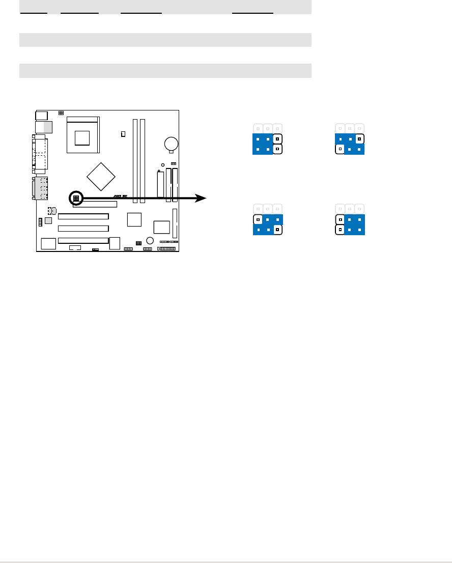
1) CPU:DRAM Frequency Setting (BSEL0, BSEL1)
This jumper sets the external CPU:DRAM frequency ratio for normal
operation. The default operates at 133:133 Mhz.
CPU DRAM BSEL0 BSEL1
133 133 [1-2] (Default) [1-2] (Default)
100 100 [1-2] [2-3]
133 100 [2-3] [1-2]
100 133 [2-3] [2-3]
A7N266-VM
3
12
123
BSEL0
BSEL0
BSEL1
BSEL1
DRAM
133MHz
DRAM
100MHz
CPU
100MHz
CPU
133MHz
®
123123
BSEL0
BSEL0
BSEL1
BSEL1
DRAM
100MHz
DRAM
133MHz
CPU
100MHz
CPU
133MHz
A7N266-VM CPU
(Default)
External Frequency Selection
ASUS A7N266-VM motherboard user guide
19
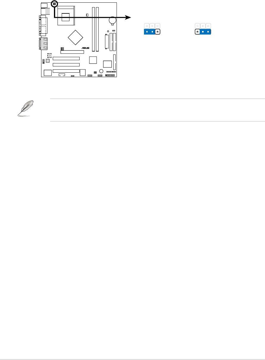
2) Keyboard Wake Up (3 pin KBPWR1)
This allows you to disable or enable the keyboard power up function. Retain
the default setting of [1-2] to use your keyboard by pressing <Spacebar> to
power up your computer. This feature requires an ATX power supply that
can supply at least 720mA on the +5VSB lead. (The computer will not power
ON if you set to [1-2] but do not have the correct ATX power supply.)
A7N266-VM
KBPWR1
1
2
2
3
+5V
+5VSB
®
(Default)
A7N266-VM Keyboard Power Setting
NOTE! This jumper must be set in conjunction with Wake On PS2 KB/
PS2 Mouse in 4.5.1 Power Up Control.
20
Chapter 2: Hardware information
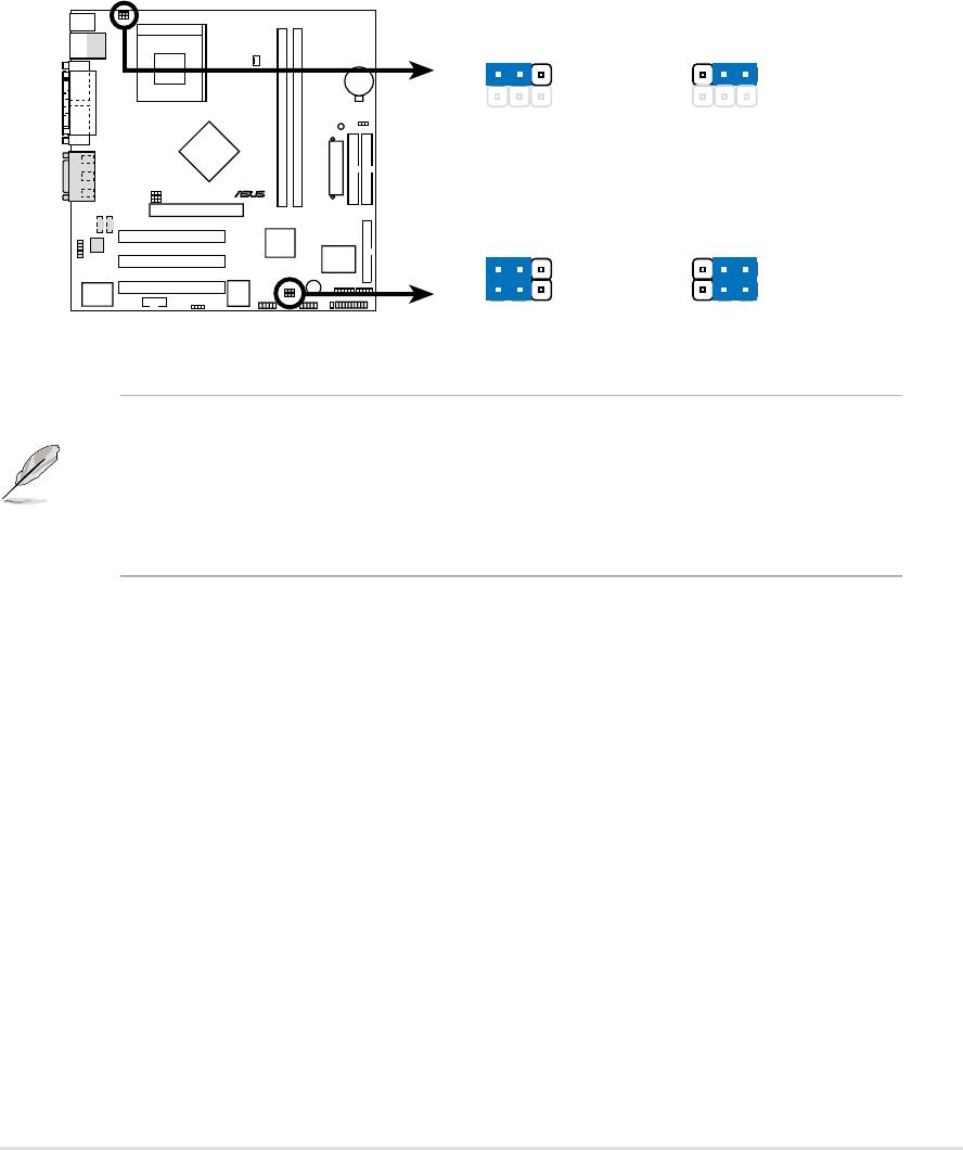
3) USB Device Wake-up (2x3 pin USBPWR01, 23, 45)
Set these jumpers to +5V to allow wake up from the S1 sleep state (CPU
stopped; RAM refreshed; system running in low power mode) using the
connected USB devices. Set to +5VSB to allow wake up from S3 sleep state
(no power to CPU; RAM in slow refresh; power supply in reduced power
mode). The default setting for the three jumpers is 1-2 to select +5V (because
not all computers have the appropriate power supply).
The USBPWR01 jumper activates the rear panel USB ports. The USBPWR23
jumper activates the internal header, USB23
A7N266-VM
USBPWR01
1
2
2
3
+5V
+5VSB
(Default)
®
USBPWR45
USBPWR23
12
23
+5V
+5VSB
A7N266-VM USB Device Wake Up
(Default)
NOTE! This feature requires an ATX power supply that can supply at
least 2A on the +5VSB lead when these jumpers are set to +5VSB.
Otherwise, the system does not power up. The total current consumed
must NOT exceed the power supply capability (+5VSB) whether under
normal working conditions or in sleep mode.
ASUS A7N266-VM motherboard user guide
21
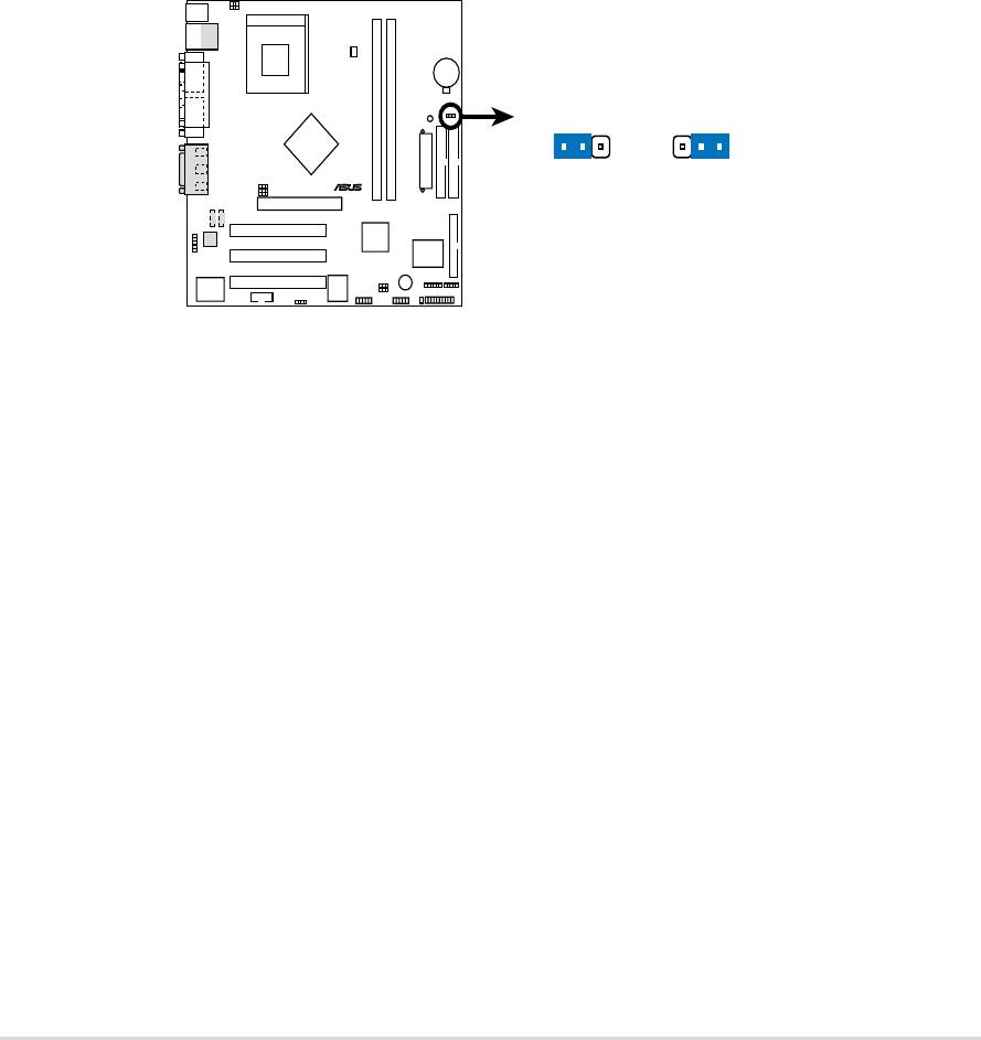
5) Clear RTC RAM (CLR_CMOS)
This jumper clears the Real Time Clock (RTC) RAM of date, time, and system
setup parameters in CMOS. The RAM data in CMOS is powered by the
onboard button cell battery.
To erase the RTC RAM:
1. Turn OFF the computer and unplug the power cord.
2. Remove the battery.
3. Short the solder points momentarily with a paper clip or other
delicate metal instrument.
4. Re-install the battery.
5. Plug the power cord and turn ON the computer.
6. Hold down the <Del> key during the boot process and enter BIOS
setup to re-enter data.
A7N266-VM
CLRTC
12
23
®
Normal Clear CMOS
(Default)
A7N266-VM Clear RTC RAM
22
Chapter 2: Hardware information
2.8 Connectors
This section describes and illustrates the internal connectors on the
motherboard.
WARNING! Some pins are used for connectors or power sources. These
are clearly distinguished from jumpers in the Motherboard Layout. Placing
jumper caps over these connector pins will cause damage to your
motherboard.
IMPORTANT! Ribbon cables should always be connected with the red
stripe to Pin 1 in the connector scoket.
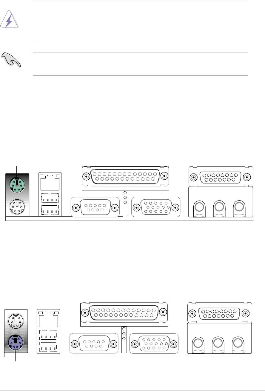
1) PS/2 Mouse Port (Green 6-pin PS2KBMS)
The system automatically directs IRQ12 to the PS/2 mouse if one is detected.
If no mouse is detected, IRQ12 become available to expansion cards. See
PS/2 Mouse Function Control in 4.4 Advanced Menu.
PS/2 Mouse (6-pin female)
2) PS/2 Keyboard Port (Purple 6-pin PS2KBMS)
This connection is for a standard keyboard using an PS/2 plug (mini DIN).
This connector does not allow standard AT size (large DIN) keyboard plugs.
You may use a DIN to mini DIN adapter on standard AT keyboards.
PS/2 Keyboard (6-pin female)
ASUS A7N266-VM motherboard user guide
23
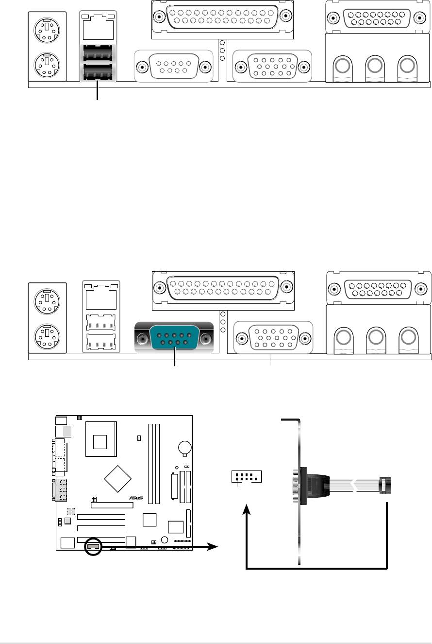
3) Universal Serial Bus Ports 0 and 1 (Black two x 4-pin USB)
Two USB ports are available for connecting USB devices.
Universal Serial Bus (USB)
4) Serial Ports
(Teal/Turquoise, One 9-pin COM1, One 10-1 pin COM2)
One serial port can be used for pointing devices or other serial devices. The
other is available as an onboard header. To enable these ports, see Onboard
Serial Port 1 / Onboard Serial Port 2 in 4.4.2 I/O Device Configuration
for the settings.
COM 1
Serial Port (9-pin male)
A7N266-VM
COM2
®
PIN 1
A7N266-VM Serial COM2 Bracket
24
Chapter 2: Hardware information
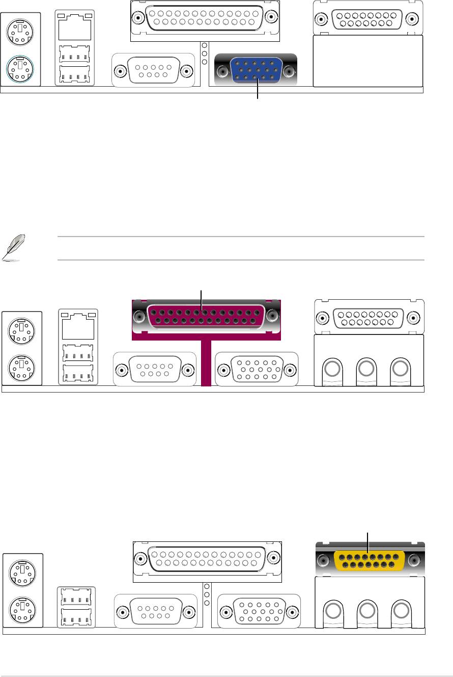
5) Monitor Output Connector (Blue 15-pin VGA)
This connector supports output to a VGA compatible screen device.
VGA Monitor (15-pin female)
6) Parallel Port (Burgundy 25-pin PRINTER)
You can enable the parallel port and choose the IRQ through Onboard
Parallel Port (see 4.4.2 I/O Device Configuration).
NOTE! Serial printers must be connected to the serial port.
Parallel (Printer) Port (25-pin female)
7) Game/MIDI Ports (Gold 15-pin GAME_AUDIO) (Optional)
This connector supports a joystick or a game pad for playing games, and
MIDI devices for playing or editing audio files.
Joystick/MIDI (15-pin female)
ASUS A7N266-VM motherboard user guide
25
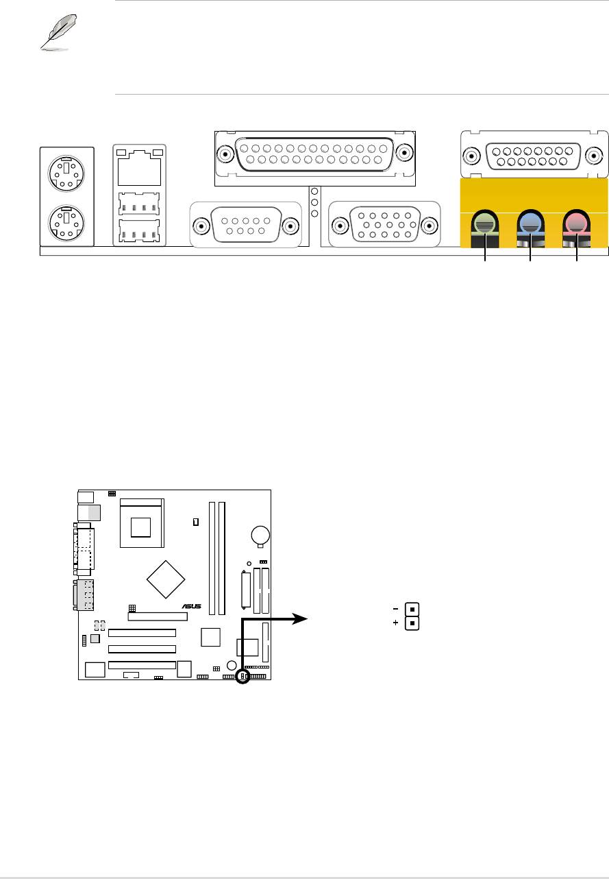
8) Audio Connectors (Three 1/8” AUDIO) (Optional)
The Line Out (lime) connects a headphone or speakers. The Line In (light
blue) connects a tape players or other audio sources. The Mic (pink) connects
a microphone.
NOTE! The functions of the audio connectors Line Out, Line In, and Mic
change when the 6-channel audio feature is enabled. Software driver
support for 6-channel audio is available at the Asus website:
www.asus.com
MicLine InLine Out
1/8" Stereo Audio Connectors
9) IDE Activity LED (2-pin IDELED)
This connector supplies power to the cabinet’s IDE activity LED. Read and
write activity by devices connected to the Primary or Secondary IDE
connectors cause the IDE LED to light up.
A7N266-VM
IDELED
®
TIP: If the case-mounted LED does not
light, try reversing the 2-pin plug.
A7N266-VM IDE Activity LED
26
Chapter 2: Hardware information
10)Floppy Disk Drive Connector (34-1 pin FLOPPY)
This connector supports the provided floppy drive ribbon cable. After
connecting the single end to the board, connect the two plugs on the other
end to the floppy drives. (Pin 5 is removed to prevent inserting in the
wrong orientation when using ribbon cables with pin 5 plugged).
A7N266-VM
®
NOTE: Orient the red markings on
the floppy ribbon cable to PIN 1
PIN 1
A7N266-VM Floppy Disk Drive Connector
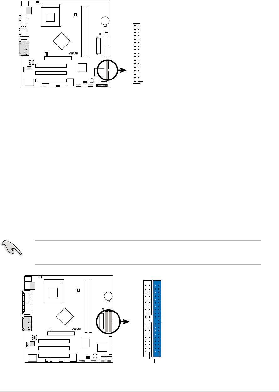
11) Primary (Blue) / Secondary (Black) IDE Connectors
(40-1 pin PRIMARY IDE and SECONDARY IDE)
The Primary and Secondary IDE connectors support the IDE hard disk ribbon
cables supplied with the motherboard. Connect the cable’s blue connector
to the motherboard’s primary IDE connector (recommended) or the secondary
IDE connector. Connect the opposite end of the cable to your UltraDMA100/
66 device (hard disk drive). If a second hard disk drive is connected,
youmay reset its jumper to Slave or Master/Slave mode. Non-UltraDMA100/
66 devices should be connected to the secondary IDE connector. BIOS
supports specific device bootup (see 4.6 Boot Menu.)
IMPORTANT! UltraDMA100 IDE devices require a 40-pin 80-conductor
cable and RAID arrays only operate with such cables.
A7N266-VM
NOTE: Orient the red markings
(usually zigzag) on the IDE
®
ribbon cable to PIN 1.
Secondary IDE Connector
Primary IDE Connector
PIN 1
A7N266-VM IDE Connectors
ASUS A7N266-VM motherboard user guide
27
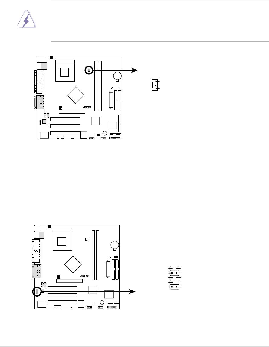
12) CPU Fan Connector (3 pin CPU_FAN)
Three fan connectors support cooling fans of 350mA (4.2 Watts) or less.
Orient the fans so that airflow flows across the onboard heat sinks instead of
expansion slots. The fan wiring and plug vary depending on the type
employed. Connect the fan cable to the connector, ensuring that the black
wire matches the ground pin. (Use the “Rotation” signal only with a specially
designed fan with a rotation signal. You can monitor the Rotations Per Minute
(RPM) using ASUS PC Probe (see 6. SOFTWARE REFERENCE).
WARNING! Make sure to connect the fan cables to the fan connectors.
Lack of sufficient airflow within the system could cause damage to the
motherboard. These are not jumpers, do not place jumper caps over
these connectors!
A7N266-VM
CPU_FAN
GND
+12V
Rotation
®
A7N266-VM 12-Volt Cooling Fan Power
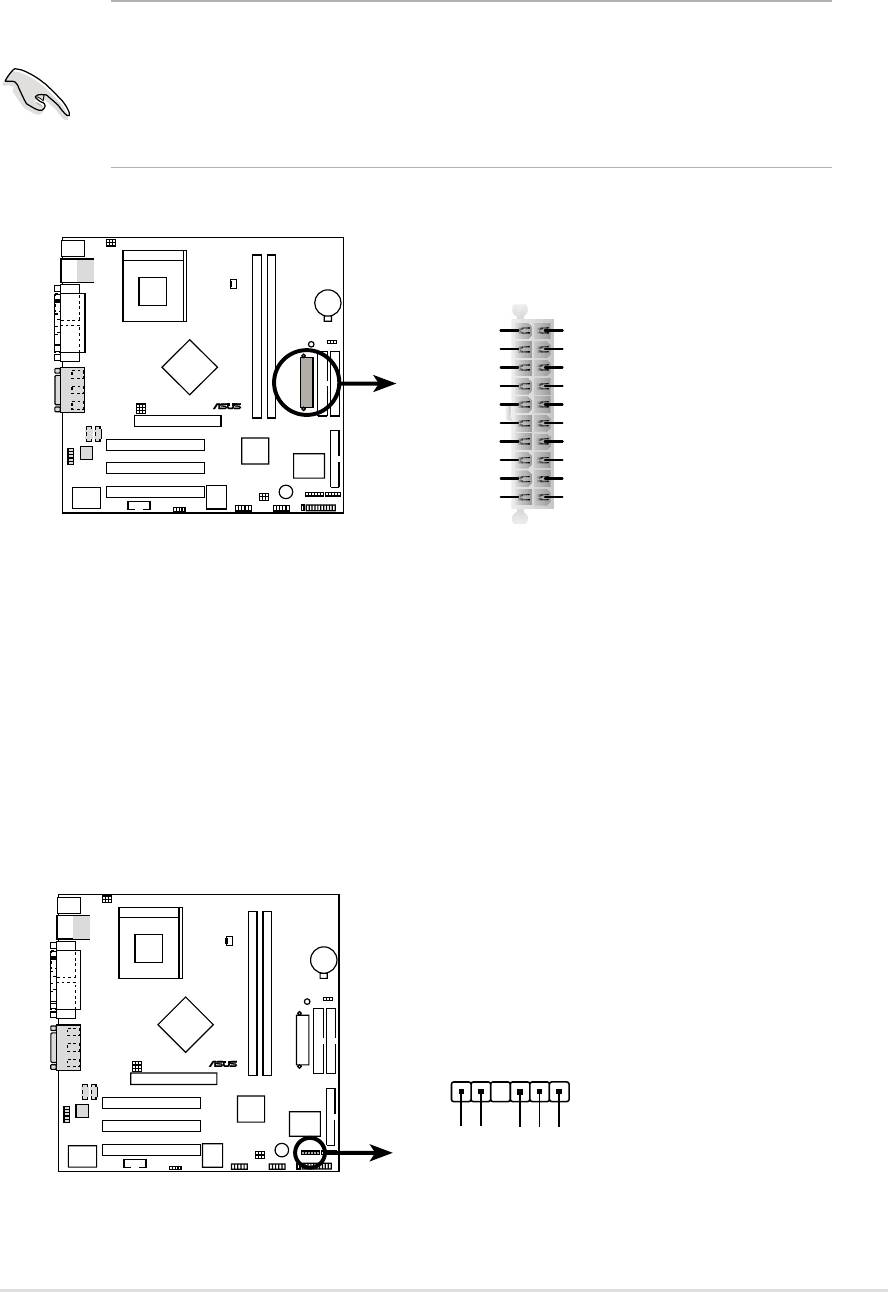
13) ASUS Front Panel Audio Connector (10 pin AAPANEL)
This connector supports an optional front audio panel. Attach the Front Panel
audio cable to the AAPANEL connector for audio control.
A7N266-VM
AAPANEL1
MIC
AGND
MICPWR
NC
®
LineOut_FR
LineOut_RR
NC
LineOut_FL
LineOut_RL
A7N266-VM Audio Panel Connector
28
Chapter 2: Hardware information
14) Power Supply Connectors (20 pin block ATXPWR)
This connector supports an ATX 12V power supply. The plug from the power
supply fits in only one orientation. Push down firmly ensuring that the pins
are aligned.
IMPORTANT! Make sure that the ATX 12V power supply offers at least
10mA on the +5-volt standby lead (+5VSB). The system may become
unstable and may experience difficulty powering up if the power supply
is inadequate. For Wake-On-LAN support, the ATX power supply must
supply at least 720mA +5VSB.
A7N266-VM
ATXPWR
+3.3VDC
+3.3VDC
-12.0VDC
+3.3VDC
COM
COM
PS_ON#
+5.0VDC
®
COM
COM
COM
+5.0VDC
COM
COM
-5.0VDC
PWR_OK
+5.0VDC
+5VSB
+5.0VDC
+12.0VDC
A7N266-VM ATX Power Connector
15) SMBus Connector (6-1 pin SMB)
This connector supports SMBus (System Management Bus) devices. SMBus
devices communicate by means of the SMBus with an SMBus host and/or
other SMBus devices. SMBus is a multi-device bus that permits multiple
chips to connect to the same bus and enable each one to act as a master by
initiating data transfer.
A7N266-VM
®
SMB
1
+3V
Ground
SMBCLK
A7N266-VM SMBus Connector
FLOATING
SMBDATA
ASUS A7N266-VM motherboard user guide
29
16) Internal Audio Connectors (Two x 4 pin CD_IN1, AUX) (Optional)
These connectors allow you to receive stereo audio input from sound sources
as a CD-ROM, TV tuner, or MPEG card.
A7N266-VM
CD_IN1
AUX
(Black)
(White)
®
Right Audio Channel
Ground
Left Audio Channel
A7N266-VM Internal Audio Connectors
17) Digital Audio Interfaces (4-1pin SPDIF1) (Optional)
These connectors supply an SPDIF audio cable that outputs digital audio.
A7N266-VM
SPDIF1
®
+5V
SPDIFOUT
GND
A7N266-VM Digital Audio Connector
30
Chapter 2: Hardware information
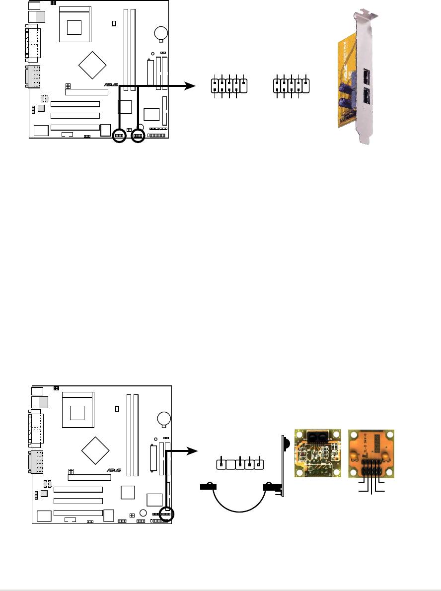
18) USB Headers (10-1 pin USB23, USB45)
If the USB port connectors on the back panel are inadequate, two USB
headers are available for four additional USB port connectors. Connect a 2-
port USB connector set to a USB header and mount the USB bracket to an
open slot in the chassis. (The USB connector set is optional and does not
come with the motherboard package.)
A7N266-VM
USB23USB45
USB Power
USBP4–
USBP4+
GND
NC
USB Power
USBP2–
USBP2+
GND
NC
15
15
®
610
610
GND
GND
USBP5–
USBP5+
USBP3–
USBP3+
USB Power
USB Power
A7N266-VM Front Panel USB Headers
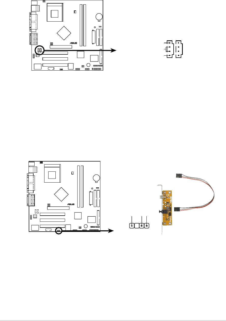
19) Infrared module connector (5-1 pin IR)
This connector supports an optional wireless transmitting and receiving
infrared module. This module mounts to a small opening on system chassis
that support this feature. You must also configure the UART2 Use As
parameter in BIOS to set UART2 for use with IR. See section “4.4.2 I/O
Device Configuration” for details.
Use the five pins as shown in Back View and connect a ribbon cable from the
module to the motherboard SIR connector according to the pin definitions.
A7N266-VM
Front View Back View
IR
+5V
IRRX
GND
IRTX
®
1
IRTX
+5V
GND
(NC)
IRRX
A7N266-VM Infrared Module Connector
ASUS A7N266-VM motherboard user guide
31

The following 20-pin PANEL illustration is for items 20-26.
A7N266-VM
Keyboard Lock
Speaker
Connector
Power LED
PLED+
PLED-
Keylock
Ground
+5V
Ground
Ground
Speaker
®
PWR
GND
MLED+
MLED-
Reset
ExtSMI#
Ground
Ground
Reset SW
Message LED
ATX Power
SMI Lead
Switch*
* Requires an ATX power supply.
A7N266-VM System Panel Connectors
20) System Power LED Lead (3-1 pin PWR_LED)
This 3-1 pin connector supplies the system power LED. The LED lights up
when the system power is on, and the LED blinks when the system is in
sleep or soft-off mode.
21) Keyboard Lock Switch Lead (2 pin KEYLOCK)
This 2-pin connector supplies the case-mounted key switch for keyboard
locking.
22) System Warning Speaker Lead (4 pin SPEAKER)
This 4-pin connector supplies the case-mounted speaker to sound system
beeps and warnings.
23) System Message LED Lead (2 pin LED)
This 2-pin connector supports the system message LED to indicate receipt
of messages from a fax/modem. The normal status for this LED is ON,
when there is no incoming data signal. The LED blinks when data is received.
The system message LED feature requires an ACPI OS and driver support.
24) System Management Interrupt Lead (2 pin SMI)
This 2-pin connector permits switching to suspend mode, or “Green” mode,
in which system activity is instantly decreased to save power and to expand
the life of certain system components. Attach the case-mounted suspend
switch this 2-pin connector.
25) ATX Power Switch / Soft-Off Switch Lead (2 pin PWR)
The system power is controlled by a momentary switch attached to this
connector. Pressing the button switches the system between ON and SLEEP,
or ON and SOFT OFF, depending on the BIOS or OS settings. Pressing the
button while in the ON mode for more than 4 seconds turns the system off.
26) Reset Switch Lead (2 pin RESET)
This 2-pin connector supports the case-mounted reset switch for rebooting
the system without turning off the power switch.
32
Chapter 2: Hardware information
