Bosch PCM 7 – page 2
Manual for Bosch PCM 7
OBJ_BUCH-880-004.book Page 21 Monday, July 19, 2010 11:56 AM
Deutsch | 21
Entfernen Sie nach jedem Arbeitsgang Staub
Österreich
und Späne durch Ausblasen mit Druckluft oder
Tel.: +43 (01) 7 97 22 20 10
mit einem Pinsel.
Fax: +43 (01) 7 97 22 20 11
Reinigen Sie regelmäßig die Gleitrolle 16.
E-Mail:
service.elektrowerkzeuge@at.bosch.com
Zubehör
Schweiz
Sägeblätter für Holz und Plattenmaterialien,
Tel.: +41 (044) 8 47 15 11
Paneelen und Leisten
Fax: +41 (044) 8 47 15 51
Sägeblatt 190 x 30 mm,
40 Zähne . . . . . . . . . . . . . . . . . . 2 609 256 821
Luxemburg
Sägeblatt 190 x 30 mm,
Tel.: +32 (070) 22 55 65
12 Zähne . . . . . . . . . . . . . . . . . . 2 609 256 868
Fax: +32 (070) 22 55 75
E-Mail: outillage.gereedschap@be.bosch.com
Sägeblatt 190 x 30 mm,
24 Zähne . . . . . . . . . . . . . . . . . . 2 608 640 615
Entsorgung
Sägeblatt 190 x 30 mm,
60 Zähne . . . . . . . . . . . . . . . . . . 2 608 641 188
Elektrowerkzeuge, Zubehör und Verpackungen
sollen einer umweltgerechten Wiederverwer-
tung zugeführt werden.
Kundendienst und Kundenberatung
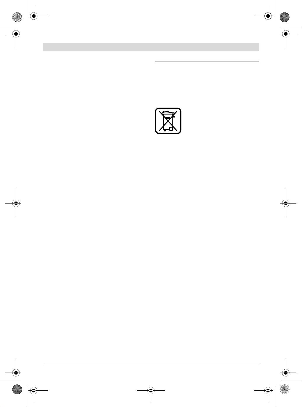
Werfen Sie Elektrowerkzeuge nicht in den Haus-
Der Kundendienst beantwortet Ihre Fragen zu
müll!
Reparatur und Wartung Ihres Produkts sowie zu
Ersatzteilen. Explosionszeichnungen und Infor-
Nur für EU-Länder:
mationen zu Ersatzteilen finden Sie auch unter:
Gemäß der Europäischen Richtli-
www.bosch-pt.com
nie 2002/96/EG über Elektro- und
Das Bosch-Kundenberater-Team hilft Ihnen ger-
Elektronik-Altgeräte und ihrer Um-
ne bei Fragen zu Kauf, Anwendung und Einstel-
setzung in nationales Recht müs-
lung von Produkten und Zubehören.
sen nicht mehr gebrauchsfähige
www.bosch-do-it.de, das Internetportal für
Elektrowerkzeuge getrennt ge-
Heimwerker und Gartenfreunde.
sammelt und einer umweltgerechten Wiederver-
www.dha.de, das komplette Service-Angebot
wertung zugeführt werden.
der Deutschen Heimwerker Akademie.
Änderungen vorbehalten.
Deutschland
Robert Bosch GmbH
Servicezentrum Elektrowerkzeuge
Zur Luhne 2
37589 Kalefeld – Willershausen
Tel. Kundendienst: +49 (1805) 70 74 10*
Fax: +49 (1805) 70 74 11*
(* Festnetzpreis 14 ct/min, höchstens 42 ct/min
aus Mobilfunknetzen)
E-Mail: Servicezentrum.Elektrowerkzeuge@de.
bosch.com
Tel. Kundenberatung: +49 (1803) 33 57 99
(Festnetzpreis 9 ct/min, höchstens 42 ct/min
aus Mobilfunknetzen)
Fax: +49 (711) 7 58 19 30
E-Mail: kundenberatung.ew@de.bosch.com
Bosch Power Tools 1 609 929 U75 | (19.7.10)
OBJ_BUCH-880-004.book Page 22 Monday, July 19, 2010 11:56 AM
22 | English
en
Safety Notes
e) When operating a power tool outdoors,
use an extension cord suitable for out-
General Power Tool Safety Warnings
door use. Use of a cord suitable for out-
door use reduces the risk of electric
When using electric tools basic
W
ARN
I
N
G
shock.
safety precautions should al-
ways be followed to reduce the risk of fire, elec-
f) If operating a power tool in a damp loca-
tric shock and personal injury including the fol-
tion is unavoidable, use a residual cur-
lowing.
rent device (RCD) protected supply. Use
of an RCD reduces the risk of electric
Read all these instructions before attempting
shock.
to operate this product and save these instruc-
tions.
3) Personal safety
The term “power tool” in the warnings refers to
a) Stay alert, watch what you are doing and
your mains-operated (corded) power tool or
use common sense when operating a
battery-operated (cordless) power tool.
power tool. Do not use a power tool
1) Work area safety
while you are tired or under the influ-
ence of drugs, alcohol or medication. A
a) Keep work area clean and well lit. Clut-
moment of inattention while operating
tered or dark areas invite accidents.
power tools may result in serious person-
b) Do not operate power tools in explosive
al injury.
atmospheres, such as in the presence of
b) Use personal protective equipment. Al-
flammable liquids, gases or dust. Power
ways wear eye protection. Protective
tools create sparks which may ignite the
equipment such as dust mask, non-skid
dust or fumes.
safety shoes, hard hat, or hearing protec-
c) Keep children and bystanders away
tion used for appropriate conditions will
while operating a power tool. Distrac-
reduce personal injuries.
tions can cause you to lose control.
c) Prevent unintentional starting. Ensure
2) Electrical safety
the switch is in the off-position before
connecting to power source and/or bat-
a) Power tool plugs must match the outlet.
tery pack, picking up or carrying the
Never modify the plug in any way. Do not
tool. Carrying power tools with your fin-
use any adapter plugs with earthed
ger on the switch or energising power
(grounded) power tools. Unmodified
tools that have the switch on invites acci-
plugs and matching outlets will reduce
dents.
risk of electric shock.
d) Remove any adjusting key or wrench be-
b) Avoid body contact with earthed or
fore turning the power tool on. A wrench
grounded surfaces, such as pipes, radia-
or a key left attached to a rotating part of
tors, ranges and refrigerators. There is
the power tool may result in personal inju-
an increased risk of electric shock if your
ry.
body is earthed or grounded.
e) Do not overreach. Keep proper footing
c) Do not expose power tools to rain or wet
and balance at all times. This enables
conditions. Water entering a power tool
better control of the power tool in unex-
will increase the risk of electric shock.
pected situations.
d) Do not abuse the cord. Never use the
f) Dress properly. Do not wear loose cloth-
cord for carrying, pulling or unplugging
ing or jewellery. Keep your hair, clothing
the power tool. Keep cord away from
and gloves away from moving parts.
heat, oil, sharp edges and moving parts.
Loose clothes, jewellery or long hair can
Damaged or entangled cords increase the
be caught in moving parts.
risk of electric shock.
1 609 929 U75 | (19.7.10) Bosch Power Tools
OBJ_BUCH-880-004.book Page 23 Monday, July 19, 2010 11:56 AM
English | 23
g) If devices are provided for the connec-
5) Service
tion of dust extraction and collection fa-
a) Have your power tool serviced by a qual-
cilities, ensure these are connected and
ified repair person using only identical
properly used. Use of dust collection can
replacement parts. This will ensure that
reduce dust-related hazards.
the safety of the power tool is maintained.
4) Power tool use and care
Safety Warnings for Chop and Mitre
a) Do not force the power tool. Use the cor-
rect power tool for your application. The
Saws
correct power tool will do the job better
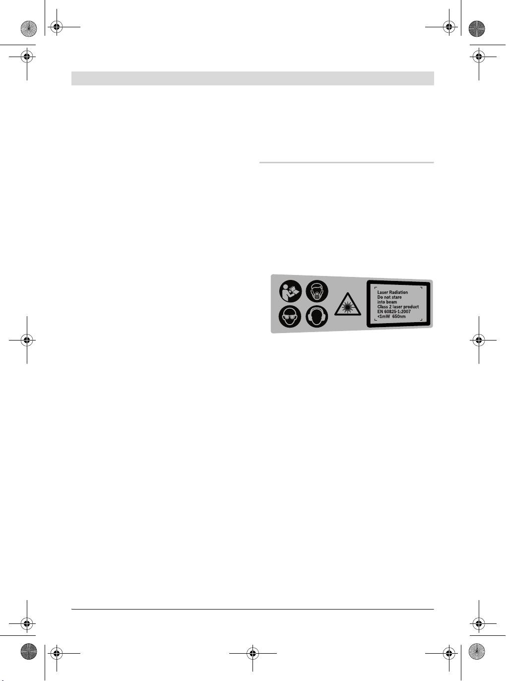
f The machine is delivered with a warning la-
and safer at the rate for which it was de-
bel in German language (marked with the
signed.
number 2 in the representation of the ma-
b) Do not use the power tool if the switch
chine on the graphic page).
does not turn it on and off. Any power
Before putting into operation for the first
tool that cannot be controlled with the
time, attach the supplied sticker in your na-
switch is dangerous and must be re-
tional language over the German warning la-
paired.
bel.
c) Disconnect the plug from the power
source and/or the battery pack from the
power tool before making any adjust-
ments, changing accessories, or storing
power tools. Such preventive safety
measures reduce the risk of starting the
power tool accidentally.
d) Store idle power tools out of the reach of
f Never make warning signs on the machine
children and do not allow persons unfa-
unrecognisable.
miliar with the power tool or these in-
f Never stand on the power tool. Serious inju-
structions to operate the power tool.
ries can occur when the power tool tips over
Power tools are dangerous in the hands of
or when inadvertently coming into contact
untrained users.
with the saw blade.
e) Maintain power tools. Check for mis-
f Make sure that the guard operates properly
alignment or binding of moving parts,
and that it can move freely. Never lock the
breakage of parts and any other condi-
guard in place when opened.
tion that may affect the power tool’s op-
f Never remove cutting remainders, wood
eration. If damaged, have the power tool
chips, etc. from the sawing area while the
repaired before use. Many accidents are
machine is running. Always guide the tool
caused by poorly maintained power tools.
arm back to the neutral position first and
f) Keep cutting tools sharp and clean. Prop-
then switch the machine off.
erly maintained cutting tools with sharp
f Guide the saw blade against the workpiece
cutting edges are less likely to bind and
only when the machine is switched on. Oth-
are easier to control.
erwise there is damage of kickback, when
g) Use the power tool, accessories and tool
the saw blade becomes wedged in the work-
bits etc. in accordance with these in-
piece.
structions, taking into account the work-
f Keep handles dry, clean, and free from oil
ing conditions and the work to be per-
and grease. Greasy, oily handles are slippery
formed. Use of the power tool for
causing loss of control.
operations different from those intended
could result in a hazardous situation.
Bosch Power Tools 1 609 929 U75 | (19.7.10)
OBJ_BUCH-880-004.book Page 24 Monday, July 19, 2010 11:56 AM
24 | English
f Operate the power tool only when the work
f Check the cable regularly and have a dam-
area to the workpiece is clear of any adjust-
aged cable repaired only through an author-
ing tools, wood chips, etc. Small pieces of
ised customer service agent for Bosch pow-
wood or other objects that come in contact
er tools. Replace damaged extension
with the rotating saw blade can strike the op-
cables. This will ensure that the safety of the
erator with high speed.
power tool is maintained.
f Keep the floor free of wood chips and mate-
f Store the machine in a safe manner when
rial remainders. You could slip or trip.
not being used. The storage location must
f Always firmly clamp the piece to be
be dry and lockable. This prevents the ma-
worked. Do not saw workpieces that are too
chine from storage damage, and from being
small to clamp. Otherwise, the clearance of
operated by untrained persons.
your hand to the rotating saw blade is too
f Do not direct the laser beam at persons or
small.
animals and do not stare into the laser
f Use the machine only for cutting the mate-
beam yourself, not even from a distance.
rials listed under Intended Use. Otherwise,
This power tool produces laser class 2 laser
the machine can be subject to overload.
radiation according to EN 60825-1. This can
lead to persons being blinded.
f If the saw blade should become jammed,
switch the machine off and hold the work-
f Do not replace the installed laser with an-
piece until the saw blade comes to a com-
other laser type. A laser that does not fit to
plete stop. To prevent kickback, the work-
this power tool could pose dangers for other
piece may not be moved until after the
persons.
machine has come to a complete stop. Cor-
f Secure the workpiece. A workpiece clamped
rect the cause for the jamming of the saw
with clamping devices or in a vice is held
blade before restarting the machine.
more secure than by hand.
f Do not use dull, cracked, bent or damaged
f Never leave the machine before it has come
saw blades. Unsharpened or improperly set
to a complete stop. Cutting tools that are
saw blades produce narrow kerf causing ex-
still running can cause injuries.
cessive friction, blade binding and kickback.
f Never use the machine with a damaged ca-
f Always use saw blades with correct size
ble. Do not touch the damaged cable and
and shape (diamond versus round) of arbor
pull the mains plug when the cable is dam-
holes. Saw blades that do not match the
aged while working. Damaged cables in-
mounting hardware of the saw will run ec-
crease the risk of an electric shock.
centrically, causing loss of control.
Products sold in GB only: Your product is fitted
f Do not use high speed steel (HSS) saw
with an BS 1363/A approved electric plug with
blades. Such saw blades can easily break.
internal fuse (ASTA approved to BS 1362).
f Do not touch the saw blade after working
If the plug is not suitable for your socket outlets,
before it has cooled. The saw blade be-
it should be cut off and an appropriate plug fit-
comes very hot while working.
ted in its place by an authorised customer serv-
ice agent. The replacement plug should have the
f Never operate the machine without the in-
same fuse rating as the original plug.
sert plate. Replace a defective insert plate.
The severed plug must be disposed of to avoid a
Without flawless insert plates, injuries are
possible shock hazard and should never be in-
possible from the saw blade.
serted into a mains socket elsewhere.
Products sold in AUS and NZ only: Use a resid-
ual current device (RCD) with a rated residual
current of 30 mA or less.
1 609 929 U75 | (19.7.10) Bosch Power Tools
OBJ_BUCH-880-004.book Page 25 Monday, July 19, 2010 11:56 AM
English | 25
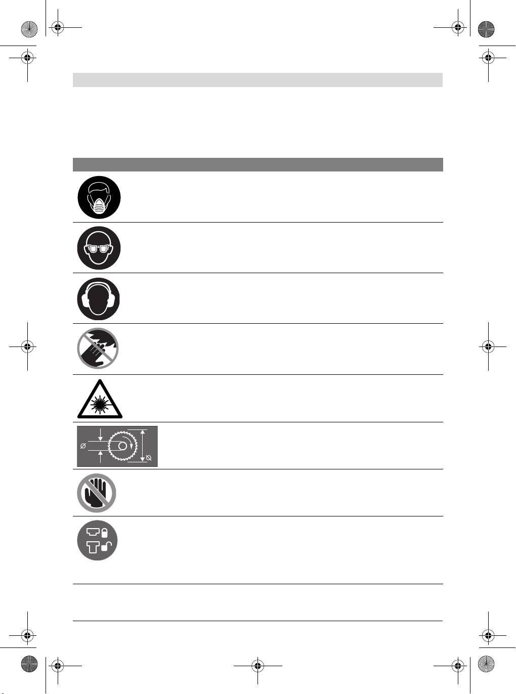
Symbols
The following symbols can be important for the operation of your power tool. Please memorise the
symbols and their meanings. The correct interpretation of the symbols helps you operate the power
tool better and more secure.
Symbol Meaning
f Wear a dust respirator.
f Wear safety goggles.
f Wear ear protectors. Exposure to noise can cause hearing loss.
f Keep hands away from the cutting area while the machine is run-
ning. Danger of injury when coming in contact with the saw blade.
f Do not direct the laser beam at persons or animals and do not stare
into the laser beam yourself, not even from a distance. This power
tool produces laser class 2 laser radiation according to EN 60825-1.
This can lead to persons being blinded.
Observe the dimensions of the saw blade. The hole diameter must
match the tool spindle without play. Do not use reducers or adapters.
30 mm
190 mm
f Danger area! Keep hands, fingers or arms away from this area.
The transport safety-lock 24 enables easier handling of the machine
when transporting to various working locations.
– Transport safety-lock 24 pushed completely inward:
Securing the Machine (Transport Position)
– Transport safety-lock 24 pulled completely outward:
Releasing the Machine (Working Position)
Bosch Power Tools 1 609 929 U75 | (19.7.10)
OBJ_BUCH-880-004.book Page 26 Monday, July 19, 2010 11:56 AM
26 | English
Symbol Meaning
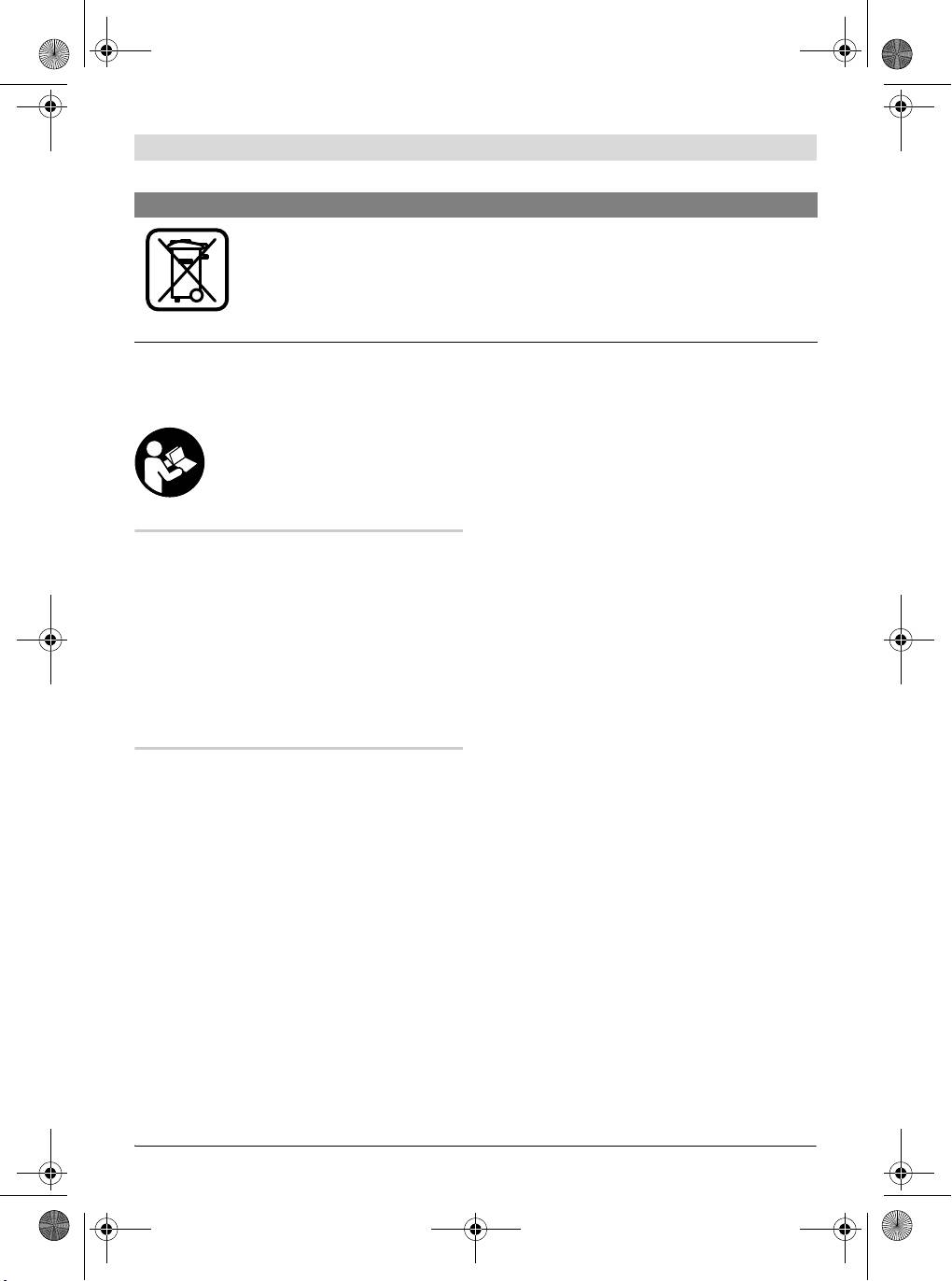
Only for EC countries:
Do not dispose of power tools into household waste!
According the European Guideline 2002/96/EC for Waste Electrical and
Electronic Equipment and its implementation into national right, power
tools that are no longer usable must be collected separately and dis-
posed of in an environmentally correct manner.
Functional Description
14 Material clamp
15 Scale for bevel angle (vertical)
Read all safety warnings and all in-
16 Roller
structions. Failure to follow the
warnings and instructions may re-
17 Saw blade
sult in electric shock, fire and/or se-
18 Dust bag
rious injury.
19 On/Off switch
20 Laser switch (for marking of cutting line)
Intended Use
21 Sawdust ejector
The power tool is intended as a stationary ma-
22 Allen key (size 6 mm)
chine for making straight lengthways and cross-
23 Clamping lever for various bevel angles
ways cuts in wood. In this, mitre angles from
(vertical)
–46° to +46° as well as bevel angles from 0° to
45° are possible.
24 Transport safety-lock
The capacity of the power tool is designed for
25 Clamping lever for any mitre angle
sawing hardwood and softwood.
26 Allen screws (6 mm) of the fence
The power tool is not suitable for cutting alumin-
27 Drill holes for material clamp
ium or other non-ferrous metals or alloys.
28 Spindle lock
29 Battery compartment
Product Features
30 Allen screw (size 6 mm) for mounting of saw
The numbering of the components shown refers
blade
to the representation of the power tool on the
31 Clamping flange
graphic pages.
32 Interior clamping flange
1 Handle
33 Wing bolt
2 Laser warning label
34 Threaded rod
3 Lever for releasing the tool arm
35 Angle indicator (horizontal)
4 Blade guard
36 Angle indicator (vertical)
5 Retracting blade guard
Accessories shown or described are not part of the
6 Fence
standard delivery scope of the product. A complete
overview of accessories can be found in our acces-
7 Insert plate
sories program.
8 Screws for insert plate
9 Handle for turning the saw table
10 Scale for mitre angle (horizontal)
11 Saw table
12 Mounting holes
13 Recessed grips
1 609 929 U75 | (19.7.10) Bosch Power Tools
OBJ_BUCH-880-004.book Page 27 Monday, July 19, 2010 11:56 AM
English | 27
The vibration emission level given in this infor-
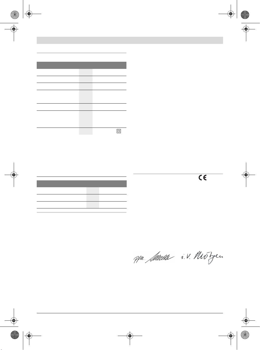
Technical Data
mation sheet has been measured in accordance
Chop and Mitre Saw PCM 7
with a standardised test given in EN 61029 and
may be used to compare one tool with another.
Article number
3 603 M01 2..
It may be used for a preliminary assessment of
Rated power input
W 1100
exposure.
-1
The declared vibration emission level repre-
No-load speed
min
4800
sents the main applications of the tool. However
Laser type
nm
650
if the tool is used for different applications, with
mW
<1
different accessories or poorly maintained, the
vibration emission may differ. This may signifi-
Laser class
2
cantly increase the exposure level over the total
Weight according to
kg 8.0
working period.
EPTA-Procedure
An estimation of the level of exposure to vibra-
01/2003
tion should also take into account the times
Protection class
/II
when the tool is switched off or when it is run-
ning but not actually doing the job. This may sig-
Permissible workpiece dimensions (maximal/minimal)
nificantly reduce the exposure level over the to-
see page 31.
tal working period.
The values given are valid for a nominal voltage [U] of
Identify additional safety measures to protect
230 V. For different voltages and models for specific
the operator from the effects of vibration such
countries, these values can vary.
as: maintain the tool and the accessories, keep
Please observe the article number on the type plate of
the hands warm, organisation of work patterns.
your machine. The trade names of the individual ma-
chines may vary.
Declaration of Conformity
Dimension of suitable saw blades
We declare under our sole responsibility that
Saw blade diameter
mm 190
the product described under “Technical Data” is
in conformity with the following standards or
Blade thickness
mm 1.4–2.5
standardization documents: EN 61029,
Mounting hole diameter
mm 30
EN 60825-1 according to the provisions of the
directives 2004/108/EC, 2006/42/EC.
Noise/Vibration Information
Technical file at:
Measured sound values determined according
Robert Bosch GmbH, Dept. PT/ESC,
to EN 61029.
D-70745 Leinfelden-Echterdingen
Typically the A-weighted noise levels of the
Dr. Egbert Schneider
Dr. Eckerhard Strötgen
product are: Sound pressure level 93 dB(A);
Senior Vice President
Head of Product
Sound power level 106 dB(A). Uncertainty
Engineering
Certification
K=3dB.
Wear hearing protection!
Vibration total values (triax vector sum) deter-
mined according to EN 61029:
Robert Bosch GmbH, Power Tools Division
2
Vibration emission value a
h
=3.0 m/s
, Uncer-
D-70745 Leinfelden-Echterdingen
2
tainty K =1.5 m/s
.
Leinfelden, 31.03.2010
Bosch Power Tools 1 609 929 U75 | (19.7.10)
OBJ_BUCH-880-004.book Page 28 Monday, July 19, 2010 11:56 AM
28 | English
Assembly
– Fasten the power tool with suitable screw
fasteners to the working surface. The holes
f Avoid unintentional starting of the ma-
12 serve for this purpose.
chine. During assembly and for all work on
the machine, the power plug must not be
Inserting the Batteries (see figure B)
connected to the mains supply.
– Open the battery compartment 29.
– Insert the batteries provided according to
Delivery Scope
the specified polarity.
Please also observe the represen-
– Close the battery compartment.
tation of the delivery scope at the
beginning of the operating instruc-
tions.
Dust/Chip Extraction
Before starting the operation of the machine for
Dusts from materials such as lead-containing
the first time, check if all parts listed below have
coatings, some wood types, minerals and metal
been supplied:
can be harmful to one’s health. Touching or
breathing-in the dusts can cause allergic reac-
– Chop and mitre saw with mounted saw blade
tions and/or lead to respiratory infections of the
– Dust bag 18
user or bystanders.
– Material clamp 14
Certain dusts, such as oak or beech dust, are
– Allen key 22
considered as carcinogenic, especially in con-
– Batteries (2x, size LR03, 1,5 V)
nection with wood-treatment additives (chro-
mate, wood preservative). Materials containing
Note: Check the power tool for possible dam-
asbestos may only be worked by specialists.
age.
Before further use of the machine, check that all
– Always use dust extraction.
protective devices are fully functional. Any light-
– Provide for good ventilation of the working
ly damaged parts must be carefully checked to
place.
ensure flawless operation of the tool. All parts
– It is recommended to wear a P2 filter-class
must be properly mounted and all conditions
respirator.
fulfilled that ensure faultless operation.
Observe the relevant regulations in your country
Damaged protective devices and parts must be
for the materials to be worked.
immediately replaced by an authorised service
centre.
The dust/chip extraction can be blocked by
dust, chips or workpiece fragments.
Additionally required tools (not in delivery
– Switch the machine off and pull the mains
scope):
plug from the socket outlet.
– Phillips screwdriver
– Wait until the saw blade has come to a com-
plete stop.
Mounting to a Working Surface
– Determine the cause of the blockage and cor-
(see figure A)
rect it.
f To ensure safe handling, the machine must
Integrated Dust Extraction (see figure C)
be mounted on a level and stable surface
– Mount the dust bag 18 onto the sawdust
(e. g., workbench) prior to using.
ejector 21.
– Carefully remove all parts included in the de-
During sawing, the dust bag must never come in-
livery from their packaging.
to contact with the movable machine parts.
– Remove all packaging material from the ma-
chine and the accessories provided.
Always empty the dust bag in good time.
1 609 929 U75 | (19.7.10) Bosch Power Tools
OBJ_BUCH-880-004.book Page 29 Monday, July 19, 2010 11:56 AM
English | 29
External Dust Extraction
Mounting the Saw Blade
For dust extraction, a vacuum hose (size
If required, clean all parts to be mounted prior
Ø 36 mm) can also be connected to the dust
to assembly.
ejector 21.
– Press lever 3, swing back the retracting
The vacuum cleaner must be suitable for the ma-
blade guard 5 to the stop and hold it in this
terial being worked.
position.
When vacuuming dry dust that is especially det-
– Place the new saw blade onto the interior
rimental to health or carcinogenic, use a special
clamping flange 32.
vacuum cleaner.
f When mounting the saw blade, pay atten-
tion that the cutting direction of the teeth
Changing the Tool (see figures D1– D4)
(arrow direction on the saw blade) corre-
sponds with the direction of the arrow on
f Before any work on the machine itself, pull
the blade guard!
the mains plug.
– Slowly guide the retracting blade guard
f When mounting the saw blade, wear protec-
downward again.
tive gloves. Danger of injury when touching
– Place on the clamping flange 31 and the
the saw blade.
screw 30.
Use only saw blades whose maximum permitted
Press the spindle lock 28 until it engages and
speed is higher than the no-load speed of the
tighten the screw turning in anticlockwise di-
power tool.
rection.
Use only saw blades that correspond with the
characteristic data given in these operation in-
structions and that are tested and marked in ac-
Operation
cordance with EN 847-1.
f Before any work on the machine itself, pull
Use only saw blades recommended by the tool
the mains plug.
manufacturer, and suitable for sawing the mate-
rials to be cut.
Transport Safety (see figure E)
Removing the Saw Blade
The transport safety-lock 24 enables easier han-
– Bring the power tool into the working posi-
dling of the machine when transporting to vari-
tion.
ous working locations.
– Turn the Allen screw 30 with the Allen key 22
Releasing the Machine (Working Position)
provided while at the same time pressing the
– Push the tool arm by the handle 1 down a lit-
spindle lock 28 until it engages.
tle in order to relieve the transport safety-
– Hold the spindle lock 28 pressed and un-
lock 24.
screw the Allen screw 30 in clockwise direc-
– Pull the transport safety-lock 24 completely
tion (left-hand thread!).
outward.
– Remove the clamping flange 31.
– Guide the tool arm slowly upward.
– Press lever 3 and swing back the retracting
blade guard 5 to the stop.
Securing the Machine (Transport Position)
– Hold the retracting blade guard in this posi-
– Tighten clamping lever 25 to lock the saw ta-
tion and remove the saw blade 17.
ble 11.
– Slowly guide the retracting blade guard
– Press lever 3 and at the same time, swing the
downward again.
tool arm by handle 1 toward the rear until the
transport safety-lock 24 can be pushed com-
pletely inward.
The tool arm is now securely locked for trans-
port.
Bosch Power Tools 1 609 929 U75 | (19.7.10)
OBJ_BUCH-880-004.book Page 30 Monday, July 19, 2010 11:56 AM
30 | English
Adjusting Vertical Bevel Angles (see figure H)
Clamping the Workpiece (see figure F)
The vertical bevel angle can be set in the range
To ensure optimum working safety, the work-
from 0° to 45°.
piece must always be firmly clamped.
– Loosen the clamping lever 23.
Do not saw workpieces that are too small to
clamp.
– Tilt the tool arm by the handle 1 until the an-
gle indicator 36 indicates the desired bevel
– Press the workpiece firmly against the
angle.
fence 6.
– Hold the tool arm in this position and retight-
– Insert the material clamp 14 provided into
en the clamping lever 23.
one of the holes 27 intended for it.
– Loosen the wing bolt 33 and adapt the mate-
For quick and precise setting of the standard
rial clamp to the workpiece. Tighten the wing
angles 0° und 45°, end stops are provided on
bolt again.
the housing.
– Firmly clamp the workpiece by turning the
– Loosen the clamping lever 23.
threaded rod 34 in clockwise direction.
– For this, tilt the tool arm by the handle 1 to
the stop toward the right (0°) or to the stop
Loosening the Workpiece
toward the left (45°).
– To release the material clamp, turn the
– Retighten the clamping lever 23 again.
threaded rod 34 in anticlockwise direction.
Starting Operation
Adjusting the Cutting Angle
f Observe correct mains voltage! The voltage
f When adjusting the cutting angle, never ac-
of the power source must agree with the
tuate the On/Off switch 19. Danger of injury
voltage specified on the nameplate of the
if the machine should accidentally start.
machine. Power tools marked with 230 V
f Before sawing, always tighten the clamping
can also be operated with 220 V.
lever 25. Otherwise the saw blade could be-
Switching On (see figure I)
come jammed in the workpiece.
–To start the machine, press the On/Off
Adjusting Horizontal Mitre Angles
switch 19 and keep it pressed.
(see figure G)
Note: For safety reasons, the On/Off switch 19
The horizontal mitre angle can be set in the
cannot be locked; it must remain pressed during
range from 46° (left side) to 46° (right side).
the entire operation.
– Release clamping lever 25, if tightened.
The tool arm can only be guided downward
This allows the saw table to move freely.
when pressing lever 3.
– Turn the saw table 11 left or right by handle
–For sawing, you must additionally press lever
9 until the angle indicator 35 indicates the
3 in addition to actuating the On/Off switch.
desired mitre angle.
– Tighten clamping lever 25 again.
Switching Off
For quick and precise setting of often used mi-
–To switch off the machine, release the
tre angles, the saw table 11 engages at the de-
On/Off switch 19.
tents of the following standard angles:
–45°/ –30°/ –22.5°/ –15°/
0°/ 15°/ 22.5°/ 30°/ 45°
1 609 929 U75 | (19.7.10) Bosch Power Tools
OBJ_BUCH-880-004.book Page 31 Monday, July 19, 2010 11:56 AM
English | 31
Minimal workpiece sizes
Working Advice
(= all workpieces that can be clamped left or
right from the saw blade with the supplied ma-
General Sawing Instructions
terial clamp 14): 100 x 40 mm (length x width)
f For all cuts, it must first be ensured that the
Cutting capacity, max. (0°/0°): 50 mm
saw blade at no time can come in contact
with the fence, screw clamps or other ma-
Cutting Off
chine parts. Remove possibly mounted aux-
– Firmly clamp the workpiece as appropriate
iliary stops or adjust them accordingly.
for its dimensions.
Protect the saw blade against impact and shock.
– Adjust the requested horizontal and/or verti-
Do not subject the saw blade to lateral pressure.
cal mitre/bevel angle.
Do not saw warped/bent workpieces. The work-
– Switch on the machine.
piece must always have a straight edge to face
– Press lever 3 and slowly guide the tool arm
against the fence.
downward by handle 1.
Long workpieces must be underlaid or support-
– Saw through the workpiece applying uniform
ed at their free end.
feed.
– Switch off the machine and wait until the
Marking the Cutting Line (see figure J)
saw blade has come to a complete stop.
A laser beam indicates the cutting line of the
– Guide the tool arm slowly upward.
saw blade. This allows for exact positioning of
the workpiece for sawing, without having to
Replacing the Insert Plate
open the retracting blade guard.
The red insert plate 7 can become worn after
– For this, switch the laser beam on with the
long use of the power tool.
switch 20.
Replace defective insert plates.
– Align the cutting mark on your workpiece
– Bring the power tool into the working posi-
with reference to the right-hand edge of the
tion.
laser line.
– Unscrew screws 8 using a Phillips screwdriv-
Position of the Operator (see figure K)
er and remove the old insert plate.
f Do not stand in a line with the saw blade in
– Insert the new insert plate and and screw all
front of the machine. Always stand aside of
screws 8 in again.
the saw blade. This protects your body
against possible kickback.
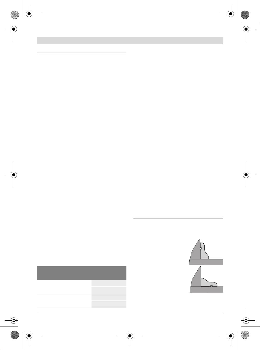
Sawing Profile Strips
– Keep hands, fingers and arms away from the
Profile strips/mouldings can be sawn in two dif-
rotating saw blade.
ferent ways:
– Do not cross your arms when operating the
– Placed against the fence
tool arm.
Permissible Workpiece Dimensions
Maximal workpiece sizes:
– Lying flat on the saw
Mitre/Bevel Angle Height x Width
table
Horizontal Vertical
0° 0°
50 x 110 mm
45° 0°
50 x 76 mm
0° 45°
37 x 110 mm
Always make trial cuts with the mitre angle set-
ting first on scrap wood.
45° 45°
37 x 76 mm
Bosch Power Tools 1 609 929 U75 | (19.7.10)
OBJ_BUCH-880-004.book Page 32 Monday, July 19, 2010 11:56 AM
32 | English
Transport
Accessories
Before transporting the power tool, the follow-
Saw blades for wood and plate materials, pan-
ing steps must be carried out:
els and strips/mouldings
– Bring the machine into the transport posi-
Saw blade 190 x 30 mm,
tion.
40 teeth . . . . . . . . . . . . . . . . . . . 2 609 256 821
– Remove all accessories that cannot be
Saw blade 190 x 30 mm,
mounted firmly to the power tool.
12 teeth . . . . . . . . . . . . . . . . . . . 2 609 256 868
If possible, place unused saw blades in an
Saw blade 190 x 30 mm,
enclosed container for transport.
24 teeth . . . . . . . . . . . . . . . . . . . 2 608 640 615
– For lifting or transporting, hold the power
Saw blade 190 x 30 mm,
tool by the recessed grips 13 on the side of
60 teeth . . . . . . . . . . . . . . . . . . . 2 608 641 188
the saw table 11.
f When transporting the power tool, use only
After-sales Service and Customer
the transport devices and never use the
Assistance
protective devices.
Our after-sales service responds to your ques-
tions concerning maintenance and repair of your
product as well as spare parts. Exploded views
Maintenance and Service
and information on spare parts can also be
found under:
www.bosch-pt.com
Maintenance and Cleaning
Our customer service representatives can an-
f Before any work on the machine itself, pull
swer your questions concerning possible appli-
the mains plug.
cations and adjustment of products and acces-
If the machine should fail despite the care taken
sories.
in manufacturing and testing procedures, repair
should be carried out by an after-sales service
Great Britain
centre for Bosch power tools.
Robert Bosch Ltd. (B.S.C.)
In all correspondence and spare parts order,
P.O. Box 98
please always include the 10-digit article
Broadwater Park
number given on the type plate of the machine.
North Orbital Road
Denham
Cleaning
Uxbridge
For safe and proper working, always keep the
UB 9 5HJ
power tool and its ventilation slots clean.
Tel. Service: +44 (0844) 736 0109
Fax: +44 (0844) 736 0146
The retracting blade guard must always be able
E-Mail: boschservicecentre@bosch.com
to move freely and retract automatically. There-
fore, always keep the area around the retracting
Ireland
blade guard clean.
Origo Ltd.
Remove dust and chips after each working pro-
Unit 23 Magna Drive
cedure by blowing out with compressed air or
Magna Business Park
with a brush.
City West
Clean the roller 16 regularly.
Dublin 24
Tel. Service: +353 (01) 4 66 67 00
Fax: +353 (01) 4 66 68 88
1 609 929 U75 | (19.7.10) Bosch Power Tools
OBJ_BUCH-880-004.book Page 33 Monday, July 19, 2010 11:56 AM
English | 33
Australia, New Zealand and Pacific Islands
Disposal
Robert Bosch Australia Pty. Ltd.
The machine, accessories and packaging should
Power Tools
be sorted for environmental-friendly recycling.
Locked Bag 66
Clayton South VIC 3169
Do not dispose of power tools into household
Customer Contact Center
waste!
Inside Australia:
Only for EC countries:
Phone: +61 (01300) 307 044
According the European Guideline
Fax: +61 (01300) 307 045
2002/96/EC for Waste Electrical
Inside New Zealand:
and Electronic Equipment and its
Phone: +64 (0800) 543 353
implementation into national
Fax: +64 (0800) 428 570
right, power tools that are no
Outside AU and NZ:
longer usable must be collected
Phone: +61 (03) 9541 5555
separately and disposed of in an environmental-
www.bosch.com.au
ly correct manner.
Republic of South Africa
Subject to change without notice.
Customer service
Hotline: +27 (011) 6 51 96 00
Gauteng – BSC Service Centre
35 Roper Street, New Centre
Johannesburg
Tel.: +27 (011) 4 93 93 75
Fax: +27 (011) 4 93 01 26
E-Mail: bsctools@icon.co.za
KZN – BSC Service Centre
Unit E, Almar Centre
143 Crompton Street
Pinetown
Tel.: +27 (031) 7 01 21 20
Fax: +27 (031) 7 01 24 46
E-Mail: bsc.dur@za.bosch.com
Western Cape – BSC Service Centre
Democracy Way, Prosperity Park
Milnerton
Tel.: +27 (021) 5 51 25 77
Fax: +27 (021) 5 51 32 23
E-Mail: bsc@zsd.co.za
Bosch Headquarters
Midrand, Gauteng
Tel.: +27 (011) 6 51 96 00
Fax: +27 (011) 6 51 98 80
E-Mail: rbsa-hq.pts@za.bosch.com
Bosch Power Tools 1 609 929 U75 | (19.7.10)
OBJ_BUCH-880-004.book Page 34 Monday, July 19, 2010 11:56 AM
34 | Français
fr
Avertissements de sécurité
b) Eviter tout contact du corps avec des
surfaces reliées à la terre telles que les
tuyaux, les radiateurs, les cuisinières et
Avertissements de sécurité généraux
les réfrigérateurs. Il existe un risque ac-
pour l’outil
cru de choc électrique si votre corps est
Lors de l’utilisation d’outil
relié à la terre.
ATTENTION
électroportatifs, respecter les
c) Ne pas exposer les outils à la pluie ou à
instructions de sécurité fondamentales suivan-
des conditions humides. La pénétration
tes afin d’éviter les risques de choc électrique,
d’eau à l’intérieur d’un outil augmentera
de blessures et d’incendie.
le risque de choc électrique.
Lire toutes les consignes avant d’utiliser cet
d) Ne pas maltraiter le cordon. Ne jamais
outil électroportatif et garder soigneusement
utiliser le cordon pour porter, tirer ou
les consignes de sécurité.
débrancher l’outil. Maintenir le cordon à
Le terme « outil » dans les consignes de sécurité
l’écart de la chaleur, du lubrifiant, des
fait référence à votre outil électrique alimenté
arêtes ou des parties en mouvement. Les
par le secteur (avec cordon d’alimentation) ou
cordons endommagés ou emmêlés aug-
votre outil fonctionnant sur batterie (sans cor-
mentent le risque de choc électrique.
don d’alimentation).
e) Lorsqu’on utilise un outil à l’extérieur,
utiliser un prolongateur adapté à l’utili-
1) Sécurité de la zone de travail
sation extérieure. L’utilisation d’un cor-
a) Conserver la zone de travail propre et
don adapté à l’utilisation extérieure réduit
bien éclairée. Les zones en désordre ou
le risque de choc électrique.
sombres sont propices aux accidents.
f) Si l’usage d’un outil dans un emplace-
b) Ne pas faire fonctionner les outils élec-
ment humide est inévitable, utiliser une
triques en atmosphère explosive, par
alimentation protégée par un dispositif à
exemple en présence de liquides inflam-
courant différentiel résiduel (RCD).
mables, de gaz ou de poussières. Les
L’usage d’un RCD réduit le risque de choc
outils électriques produisent des étincel-
électrique.
les qui peuvent enflammer les poussières
ou les fumées.
3) Sécurité des personnes
c) Maintenir les enfants et les personnes
a) Rester vigilant, regarder ce que vous
présentes à l’écart pendant l’utilisation
êtes en train de faire et faire preuve de
de l’outil. Les distractions peuvent vous
bon sens dans l’utilisation de l’outil. Ne
faire perdre le contrôle de l’outil.
pas utiliser un outil lorsque vous êtes fa-
tigué ou sous l’emprise de drogues, d’al-
2) Sécurité électrique
cool ou de médicaments. Un moment
a) Il faut que les fiches de l’outil électrique
d’inattention en cours d’utilisation d’un
soient adaptées au socle. Ne jamais mo-
outil peut entraîner des blessures graves
difier la fiche de quelque façon que ce
des personnes.
soit. Ne pas utiliser d’adaptateurs avec
b) Utiliser un équipement de sécurité. Tou-
des outils à branchement de terre. Des fi-
jours porter une protection pour les
ches non modifiées et des socles adaptés
yeux. Les équipements de sécurité tels
réduiront le risque de choc électrique.
que les masques contre les poussières,
les chaussures de sécurité antidérapan-
tes, les casques ou les protections acous-
tiques utilisés pour les conditions appro-
priées réduiront les blessures des
personnes.
1 609 929 U75 | (19.7.10) Bosch Power Tools
OBJ_BUCH-880-004.book Page 35 Monday, July 19, 2010 11:56 AM
Français | 35
c) Eviter tout démarrage intempestif. S’as-
c) Débrancher la fiche de la source d’ali-
surer que l’interrupteur est en position
mentation en courant et/ou le bloc de
arrêt avant de brancher l’outil au secteur
batteries de l’outil avant tout réglage,
et/ou au bloc de batteries, de le ramas-
changement d’accessoires ou avant de
ser ou de le porter. Porter les outils en
ranger l’outil. De telles mesures de sécu-
ayant le doigt sur l’interrupteur ou bran-
rité préventives réduisent le risque de dé-
cher des outils dont l’interrupteur est en
marrage accidentel de l’outil.
position marche est source d’accidents.
d) Conserver les outils à l’arrêt hors de la
d) Retirer toute clé de réglage avant de
portée des enfants et ne pas permettre à
mettre l’outil en marche. Une clé laissée
des personnes ne connaissant pas l’outil
fixée sur une partie tournante de l’outil
ou les présentes instructions de le faire
peut donner lieu à des blessures de per-
fonctionner. Les outils sont dangereux
sonnes.
entre les mains d’utilisateurs novices.
e) Ne pas se précipiter. Garder une posi-
e) Observer la maintenance de l’outil. Véri-
tion et un équilibre adaptés à tout mo-
fier qu’il n’y a pas de mauvais alignement
ment. Cela permet un meilleur contrôle
ou de blocage des parties mobiles, des
de l’outil dans des situations inattendues.
pièces cassées ou toute autre condition
f) S’habiller de manière adaptée. Ne pas
pouvant affecter le fonctionnement de
porter de vêtements amples ou de bi-
l’outil. En cas de dommages, faire répa-
joux. Garder les cheveux, les vêtements
rer l’outil avant de l’utiliser. De nom-
et les gants à distance des parties en
breux accidents sont dus à des outils mal
mouvement. Des vêtements amples, des
entretenus.
bijoux ou les cheveux longs peuvent être
f) Garder affûtés et propres les outils per-
pris dans des parties en mouvement.
mettant de couper. Des outils destinés à
g) Si des dispositifs sont fournis pour le
couper correctement entretenus avec des
raccordement d’équipements pour l’ex-
pièces coupantes tranchantes sont moins
traction et la récupération des poussiè-
susceptibles de bloquer et sont plus faci-
res, s’assurer qu’ils sont connectés et
les à contrôler.
correctement utilisés. Utiliser des collec-
g) Utiliser l’outil, les accessoires et les la-
teurs de poussière peut réduire les ris-
mes etc., conformément à ces instruc-
ques dus aux poussières.
tions, en tenant compte des conditions
de travail et du travail à réaliser. L’utili-
4) Utilisation et entretien de l’outil
sation de l’outil pour des opérations diffé-
a) Ne pas forcer l’outil. Utiliser l’outil adap-
rentes de celles prévues pourrait donner
té à votre application. L’outil adapté réa-
lieu à des situations dangereuses.
lisera mieux le travail et de manière plus
sûre au régime pour lequel il a été cons-
5) Maintenance et entretien
truit.
a) Faire entretenir l’outil par un réparateur
b) Ne pas utiliser l’outil si l’interrupteur ne
qualifié utilisant uniquement des pièces
permet pas de passer de l’état de mar-
de rechange identiques. Cela assurera
che à arrêt et vice versa. Tout outil qui ne
que la sécurité de l’outil est maintenue.
peut pas être commandé par l’interrup-
teur est dangereux et il faut le faire répa-
rer.
Bosch Power Tools 1 609 929 U75 | (19.7.10)
OBJ_BUCH-880-004.book Page 36 Monday, July 19, 2010 11:56 AM
36 | Français
f N’utiliser l’outil électroportatif que si aucun
Avertissements de sécurité pour scies à
outil de travail, de copeaux de bois etc.,
onglets
sauf la pièce à travailler, ne se trouve sur la
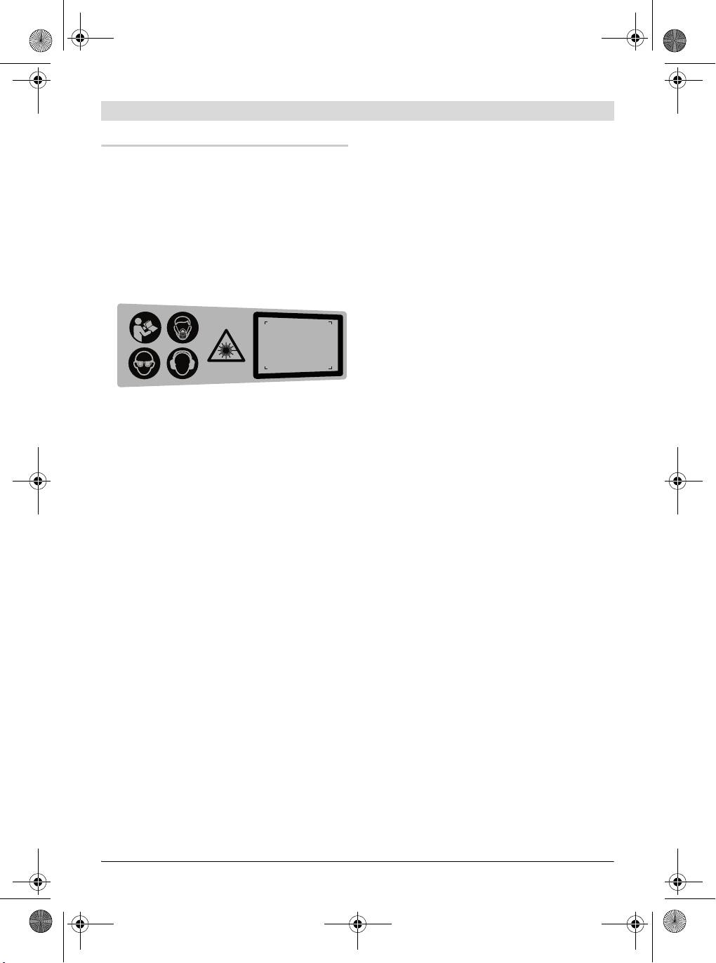
f Cet outil électroportatif est fourni avec une
surface de travail. Les petits morceaux de
plaque d’avertissement en langue alleman-
bois ou tout autre objet entrant en contact
de (dans la représentation de l’outil électro-
avec la lame de scie peut être projeté à gran-
portatif se trouvant sur la page des graphi-
de vitesse sur l’utilisateur.
ques elle est marquée du numéro 2).
f Maintenez le sol exempt de copeaux de
Avant la première mise en service, recou-
bois et de restes de matériau. Vous pourriez
vrir le texte allemand de la plaque d’avertis-
glisser ou trébucher.
sement par l’autocollant dans votre langue.
f Toujours serrer la pièce à travailler. Ne pas
travailler les pièces qui sont trop petites
Rayonnement laser
pour être serrées. La distance entre votre
ne pas regarder
dans le faisceau
main et la lame de scie en rotation serait,
appareil à laser
de classe 2
EN 60825-1:2007
dans un tel cas, trop petite.
<1mW 650nm
f N’utiliser l’outil électrique que pour les ma-
tériaux mentionnés dans le chapitre utilisa-
tion conforme. Autrement, ceci risquerait de
f S’assurer que les panneaux d’avertisse-
surcharger l’outil électrique.
ment se trouvant sur l’outil électroportatif
f Si la lame se coince arrêtez l’outil électro-
soient toujours lisibles.
portatif et maintenez la pièce fermement
f Ne jamais se placer sur l’outil électroporta-
jusqu’à l’arrêt total de la lame. Pour éviter
tif. Des blessures graves peuvent se produi-
un rebond, la pièce ne doit être bougée
re si l’outil électroportatif se renversait ou
qu’après l’arrêt complet de la lame. Elimi-
dans le cas d’un contact accidentel avec la la-
nez la cause du coinçage de la lame avant de
me.
redémarrer l’outil électroportatif.
f S’assurer que le capot de protection fonc-
f Ne pas utiliser de lames émoussées, fissu-
tionne correctement et qu’il puisse bouger
rées, déformées ou endommagées. Les la-
librement. Ne jamais coincer le capot de pro-
mes aux dents émoussées ou qui ne sont
tection s’il est ouvert.
plus alignées causent une fente de sciage
f Ne jamais enlever des résidus, des copeaux
trop étroite qui provoque une friction trop
de bois ou similaires de la zone de coupe
élevée, un plus grand risque de coincement
pendant le fonctionnement de l’outil élec-
de la lame et de par là d’un contrecoup.
troportatif. Mettre toujours le bras de l’outil
f Toujours utiliser des lames de scie de la
en position de repos puis éteindre l’outil
bonne taille, de forme appropriée à l’alésa-
électroportatif.
ge de fixation (par ex. en étoile ou rondes).
f Ne guider la lame de scie contre la pièce à
Des lames ne convenant pas aux pièces de
travailler que quand l’appareil est en mar-
montage de la scie ne tournent pas rond et
che. Sinon, il y a risque d’un contrecoup, au
conduisent à une perte de contrôle.
cas où la lame de scie se coincerait dans la
f Ne pas utiliser de lames en acier HSS
pièce.
(aciers super rapides). De telles lames se
f Garder les poignées sèches, propres et dé-
cassent facilement.
pourvues d’huile et de graisse. Des poi-
f
Ne pas toucher la lame de scie avant qu’elle
gnées grasses, huileuses sont glissantes et
ne soit refroidie. La lame de scie chauffe
provoquent ainsi une perte de contrôle.
énormément durant le travail.
1 609 929 U75 | (19.7.10) Bosch Power Tools
OBJ_BUCH-880-004.book Page 37 Monday, July 19, 2010 11:56 AM
Français | 37
f Ne jamais utiliser l’outil sans plaque. Rem-
f Ne pas remplacer le laser incorporé contre
placer une plaque défectueuse. Une plaque
un laser d’un autre type. Un laser qui ne cor-
impeccable est indispensable, car autrement
respond pas à cet outil électroportatif pour-
vous pourriez vous blesser avec la lame de
rait présenter des danger pour les person-
scie.
nes.
f Contrôler le câble régulièrement et ne faire
f Bloquer la pièce à travailler. Une pièce à tra-
réparer un câble endommagé que par un
vailler serrée par des dispositifs de serrage
Service Après-Vente autorisé pour outillage
appropriés ou dans un étau est fixée de ma-
électroportatifs Bosch. Remplacer un câble
nière plus sûre que tenue dans les mains.
de rallonge endommagé. Ceci est indispen-
f Ne jamais quitter l’outil avant son arrêt to-
sable pour assurer le bon fonctionnement en
tal. Les outils de travail qui ne sont pas enco-
toute sécurité de l’outil électrique.
re en arrêt total peuvent causer des blessu-
f En cas de non-utilisation, conservez l’outil
res.
électrique dans un endroit sûr. L’emplace-
f Ne jamais utiliser un outil électroportatif
ment de stockage doit être sec et verrouilla-
dont le câble est endommagé. Ne pas tou-
ble. Ceci prévient l’endommagement de
cher à un câble endommagé et retirer la fi-
l’outil électrique pendant le stockage ou son
che du câble d’alimentation de la prise de
utilisation par des personnes non initiées.
courant, au cas où le câble aurait été en-
f Ne pas diriger le faisceau laser vers des per-
dommagé lors du travail. Un câble endom-
sonnes ou des animaux et ne jamais regar-
magé augmente le risque de choc électrique.
der soi-même dans le faisceau laser. Cet
outil électroportatif génère des rayonne-
ments laser Classe laser 2 suivant
EN 60825-1. D’autres personnes peuvent
être éblouies.
Symboles
Les symboles suivants peuvent être importants pour l’utilisation de votre outil électroportatif.
Veuillez mémoriser les symboles et leur signification. L’interprétation correcte des symboles vous
permettra de mieux utiliser votre outil électroportatif et en toute sécurité.
Symbole Signification
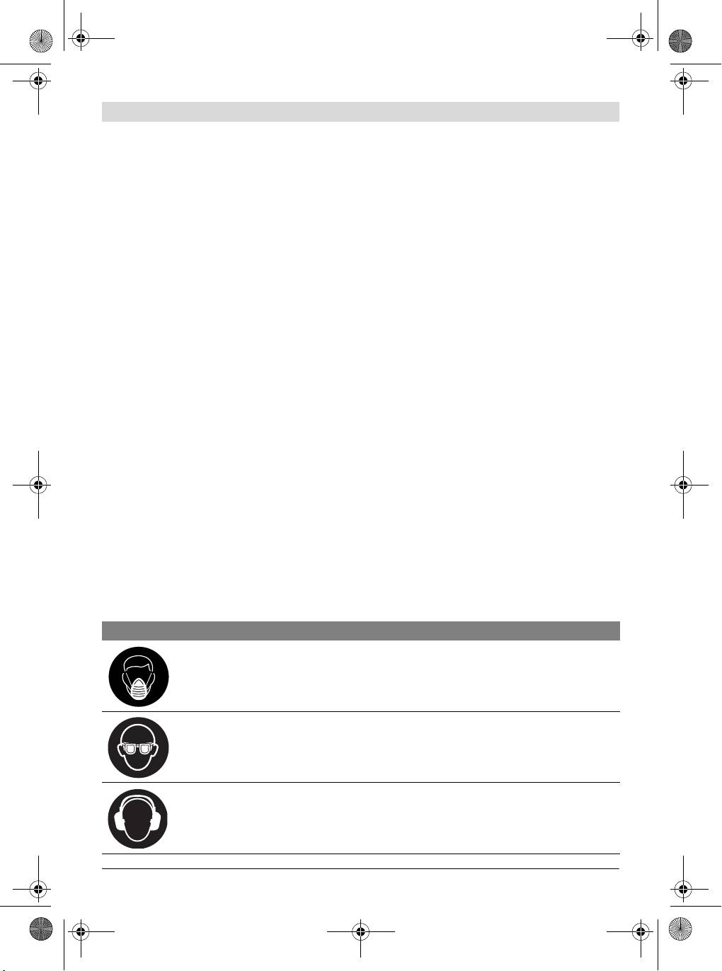
f Portez un masque anti-poussières.
f Porter toujours des lunettes de protection.
f Porter des protections auditives. L’exposition aux bruits peut pro-
voquer une perte de l’audition.
Bosch Power Tools 1 609 929 U75 | (19.7.10)
OBJ_BUCH-880-004.book Page 38 Monday, July 19, 2010 11:56 AM
38 | Français
Symbole Signification
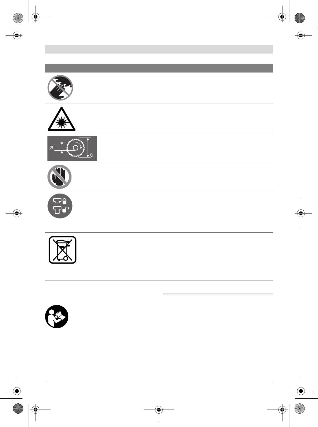
f Maintenir les mains hors de la zone de sciage pendant le fonction-
nement de l’outil électroportatif. Lors d’un contact avec la lame de
scie, il y a risque de blessures.
f Ne pas diriger le faisceau laser vers des personnes ou des animaux
et ne jamais regarder soi-même dans le faisceau laser. Cet outil
électroportatif génère des rayonnements laser Classe laser 2 suivant
EN 60825-1. D’autres personnes peuvent être éblouies.
Faire attention aux dimensions de la lame de scie. Le diamètre du trou
central doit correspondre très exactement à celui de la broche porte-
30 mm
190 mm
outil (pas de jeu). N’utiliser ni raccords réducteurs ni adaptateurs.
f Zone dangereuse ! Si possible, maintenir les mains, doigts ou bras
éloignés de cette zone.
Le dispositif de protection pour le transport 24 facilite le maniement de
l’outil électroportatif lors du transport sur différents lieux de travail.
– Dispositif de protection pour transport 24 complètement poussé vers
l’intérieur : Bloquez l’outil électroportatif (position de transport)
– Dispositif de protection pour transport 24 complètement tiré vers
l’extérieur : Débloquez l’outil électroportatif (position travail)
Seulement pour les pays de l’Union Européenne :
Ne jetez pas votre appareil électroportatif avec les ordures ménagères !
Conformément à la directive européenne 2002/96/CE relative aux dé-
chets d’équipements électriques et électroniques et sa mise en vigueur
conformément aux législations nationales, les outils électroportatifs
dont on ne peut plus se servir doivent être isolés et suivre une voie de
recyclage appropriée.
Description du fonctionnement
Utilisation conforme
Il est impératif de lire toutes les
L’outil électroportatif, un appareil sur pieds, est
consignes de sécurité et toutes les
conçu pour effectuer des coupes droites longi-
instructions. Le non-respect des
tudinales et transversales dans le bois. Des an-
avertissements et instructions indi-
gles d’onglet horizontaux de –46° à +46° ainsi
qués ci-après peut conduire à une
que des angles d’onglet verticaux de 0° à 45°
électrocution, un incendie et/ou de
sont possibles.
graves blessures.
La puissance de l’outil électroportatif est con-
çue pour le sciage de bois tendre et de bois dur.
L’outil électroportatif n’est pas approprié pour
scier l’aluminium ou d’autres métaux non fer-
reux.
1 609 929 U75 | (19.7.10) Bosch Power Tools
OBJ_BUCH-880-004.book Page 39 Monday, July 19, 2010 11:56 AM
Français | 39
31 Bride de serrage
Eléments de l’appareil
32 Bride de serrage intérieure
La numérotation des éléments de l’appareil se
33 Vis papillon
réfère à la représentation de l’outil électroporta-
34 Tige filetée
tif sur les pages graphiques.
35 Indicateur d’angle (horizontal)
1 Poignée
36 Indicateur d’angle (vertical)
2 Plaque signalétique du laser
Les accessoires décrits ou illustrés ne sont pas tous
3 Levier pour desserrer le bras d’outil
compris dans la fourniture. Vous trouverez les acces-
4 Capot de protection
soires complets dans notre programme d’accessoi-
5 Capot de protection à mouvement
res.
pendulaire
6 Butée
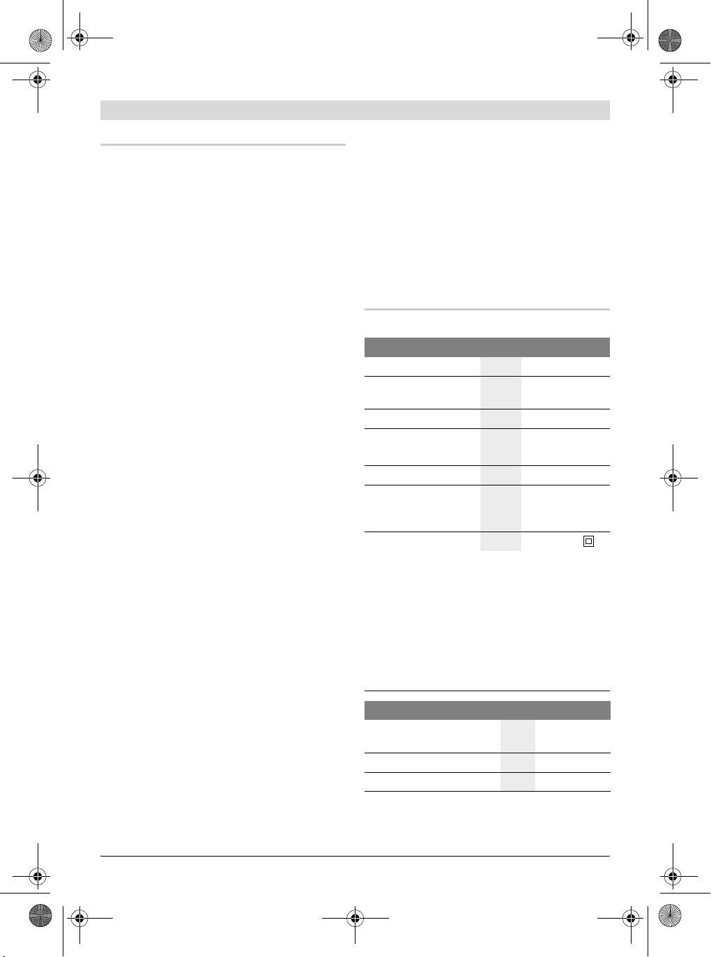
Caractéristiques techniques
7 Plaque
Scie à onglets PCM 7
8 Vis pour plaque
9 Etrier pour tourner la table de sciage
N° d’article
3 603 M01 2..
10 Graduation pour angle d’onglet (horizontal)
Puissance nominale
W 1100
11 Table de sciage
absorbée
12 Alésages pour le montage
Vitesse à vide
tr/min 4800
13 Poignées encastrées
Type de laser
nm
650
14 Serre-joint à serrage par vis
mW
<1
15 Graduation pour angle d’onglet (vertical)
Classe laser
2
16 Rouleau glisseur
Poids suivant
kg 8,0
17 Lame de scie
EPTA-Procedure
18 Sac à poussières
01/2003
19 Interrupteur Marche/Arrêt
Classe de protection
/II
20 Interrupteur pour laser (marquage du tracé
Dimensions admissibles de la pièce (max./min.), voir
de coupe)
page 44.
21 Ejection des copeaux
Ces indications sont valables pour une tension nomina-
22 Clé mâle pour vis à six pans creux (6 mm)
le de [U] 230 V. Ces indications peuvent varier pour
23 Bouton de serrage pour angle d’onglet quel-
des tensions plus basses ainsi que pour des versions
spécifiques à certains pays.
conque (vertical)
Respectez impérativement le numéro d’article se trou-
24 Dispositif de protection pour le transport
vant sur la plaque signalétique de l’outil électroportatif.
25 Levier de serrage pour angle d’onglet quel-
Les désignations commerciales des différents outils
conque (horizontal)
électroportatifs peuvent varier.
26 Vis à six pans creux (6 mm) de la butée
27 Alésages pour serre-joint à serrage par vis
Dimensions des lames de scie appropriées
28 Blocage de la broche
Diamètre de la lame de
29 Compartiment à piles
scie
mm 190
30 Vis à six pans creux (6 mm) du porte-lame
Epaisseur de la lame
mm 1,4–2,5
Diamètre de l’alésage
mm 30
Bosch Power Tools 1 609 929 U75 | (19.7.10)
OBJ_BUCH-880-004.book Page 40 Monday, July 19, 2010 11:56 AM
40 | Français
Niveau sonore et vibrations
Déclaration de conformité
Valeurs de mesure du niveau sonore détermi-
Nous déclarons sous notre propre responsabili-
nées conformément à la norme EN 61029.
té que le produit décrit sous « Caractéristiques
Les mesures réelles (A) des niveaux sonores de
techniques » est en conformité avec les normes
l’appareil sont : niveau de pression acoustique
ou documents normatifs suivants :
93 dB(A) ; niveau d’intensité acoustique
EN 61029, EN 60825-1 conformément aux ter-
106 dB(A). Incertitude K=3 dB.
mes des réglementations 2004/108/CE,
Porter une protection acoustique !
2006/42/CE.
Valeurs totales des vibrations (somme vectoriel-
Dossier technique auprès de :
le des trois axes directionnels) relevées confor-
Robert Bosch GmbH, Dept. PT/ESC,
mément à la norme EN 61029 :
D-70745 Leinfelden-Echterdingen
2
Valeur d’émission vibratoire a
h
=3,0 m/s
, incer-
Dr. Egbert Schneider
Dr. Eckerhard Strötgen
2
titude K=1,5m/s
.
Senior Vice President
Head of Product
Le niveau d’oscillation indiqué dans ces instruc-
Engineering
Certification
tions d’utilisation a été mesuré conformément à
la norme EN 61029 et peut être utilisé pour une
comparaison d’outils électroportatifs. Il est éga-
lement approprié pour une estimation prélimi-
Robert Bosch GmbH, Power Tools Division
naire de la charge vibratoire.
D-70745 Leinfelden-Echterdingen
Le niveau d’oscillation correspond aux utilisa-
Leinfelden, 31.03.2010
tions principales de l’outil électroportatif. Si
l’outil électrique est cependant utilisé pour
d’autres applications, avec d’autres outils de
Montage
travail ou avec un entretien non approprié, le ni-
veau d’oscillation peut être différent. Ceci peut
f Evitez un démarrage par mégarde de l’outil
augmenter considérablement la charge vibratoi-
électroportatif. Pendant le montage et lors
re pendant toute la durée de travail.
de travaux sur l’outil électroportatif, la fi-
Pour une estimation précise de la charge vibra-
che de secteur ne doit pas être connectée à
toire, il est recommandé de prendre aussi en
l’alimentation en courant.
considération les périodes pendant lesquelles
l’appareil est éteint ou en fonctionnement, mais
Accessoires fournis
pas vraiment utilisé. Ceci peut réduire considé-
Respectez également l’indication
rablement la charge vibratoire pendant toute la
du contenu de l’emballage au dé-
durée de travail.
but des instructions d’utilisation.
Déterminez des mesures de protection supplé-
mentaires pour protéger l’utilisateur des effets
des vibrations, telles que par exemple : Entre-
Avant la première mise en service de l’outil élec-
tien de l’outil électrique et des outils de travail,
troportatif, vérifiez si toutes les pièces indi-
maintenir les mains chaudes, organisation des
quées ci-dessous ont été fournies :
opérations de travail.
– Scie à onglets avec lame montée
– Sac à poussières 18
– Serre-joint à serrage par vis 14
– Clé mâle pour vis à six pans 22
– Piles (2x, type LR03, 1,5 V)
1 609 929 U75 | (19.7.10) Bosch Power Tools