Yamaha R-S201 Silver: PREPARATION
PREPARATION: Yamaha R-S201 Silver
PREPARATION
CONNECTIONS
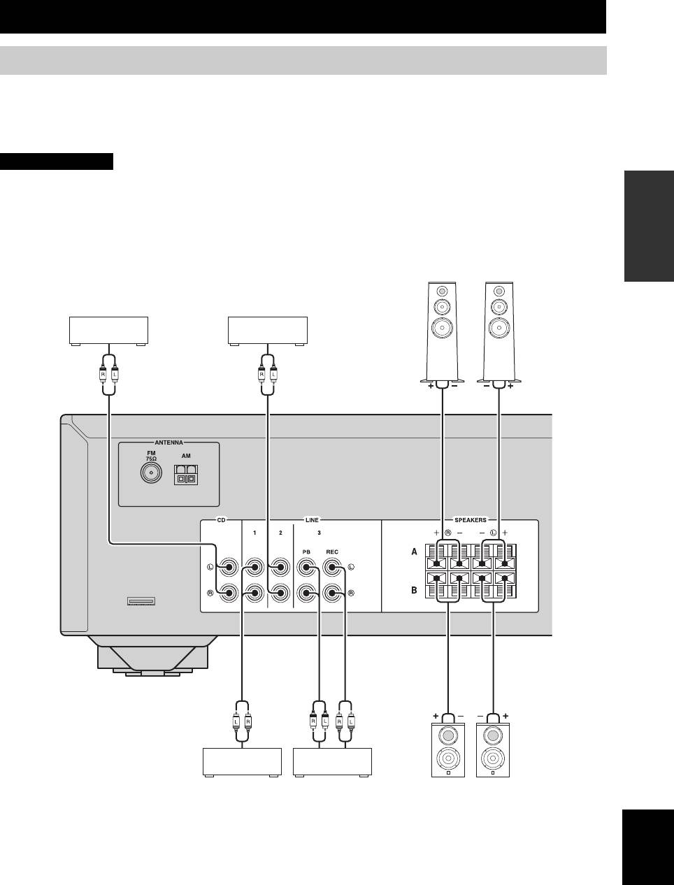
Connecting speakers and source components
Make sure to connect L (left) to L, R (right) to R, “+” to “+” and “–” to “–”. If the connections are faulty, no sound will
be heard from the speakers, and if the polarity of the speaker connections is incorrect, the sound will be unnatural and
lack bass. Refer to the owner’s manual for each of your components.
Make sure to use RCA cables to connect audio components.
CAUTION
PREPARATION
• Do not connect this unit or other components to the main power until all connections between components are
complete.
• Do not let bare speaker wires touch each other or any metal part of this unit. This could damage this unit and/or the
speakers.
Speakers A
Right
Left
CD player
Tape deck, etc.
Audio
Audio
out
out
Audio
Audio
Audio
out
out
in
DVD player,
CD recorder,
LeftRight
etc.
etc.
Speakers B
English
9 En
CONNECTIONS
■ REC jacks
■ Bi-wire connection
• The REC jacks output audio signals of the currently
Bi-wire connection separates the woofer from the
selected input (except when LINE 3 is selected).
combined midrange and tweeter section.
• Volume level, tone control and balance settings do not
A bi-wire compatible speaker has four binding post
affect the REC jacks.
terminals. These two sets of terminals allow the speaker to
be split into two independent sections. With these
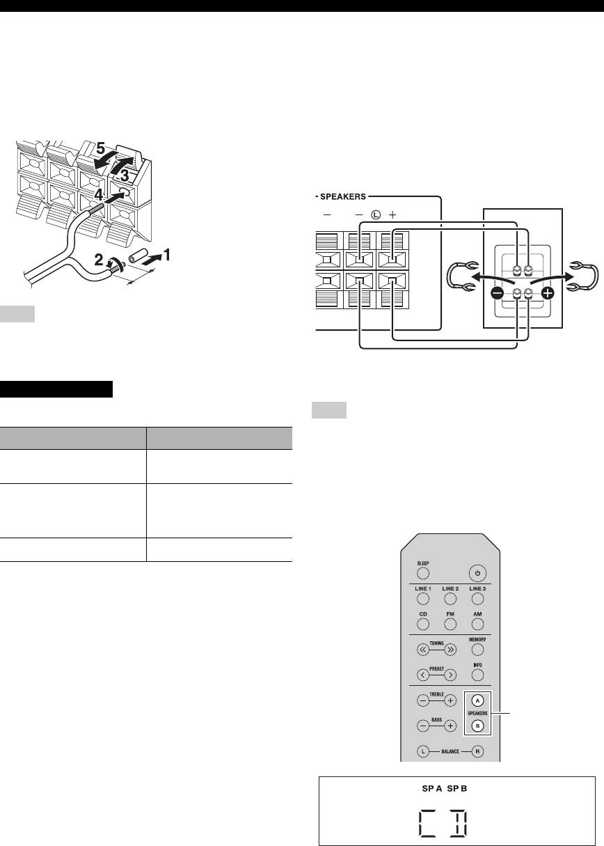
■ Connecting speaker cables
connections, the mid and high frequency drivers are
connected to one set of terminals and the low frequency
driver to another set of terminals.
Rear panel
Speaker
Remove approximately
10 mm (3/8 in) of
insulation from the end of
each speaker cable.
Note
When inserting speaker cables into the speaker terminals, insert
only the bare speaker wire. If insulated cable is inserted, the
connection may be poor and sound may not be heard.
Connect the other speaker to the other set of terminals in
the same way.
CAUTION
Speaker impedance must be set as shown below.
Note
Speaker connection Speaker impedance
When making bi-wire connections, remove the shorting bridges
or cables on the speaker.
SPEAKERS A or
8 Ω or higher
SPEAKERS B
y
To use the bi-wire connections, press SPEAKERS A and
SPEAKERS A and
16 Ω or higher
SPEAKERS B so that both SP A and B light up on the front panel
SPEAKERS B
(except for North
display.
America model)
Bi-wiring
8 Ω or higher
SPEAKERS A/B
10 En
CONNECTIONS
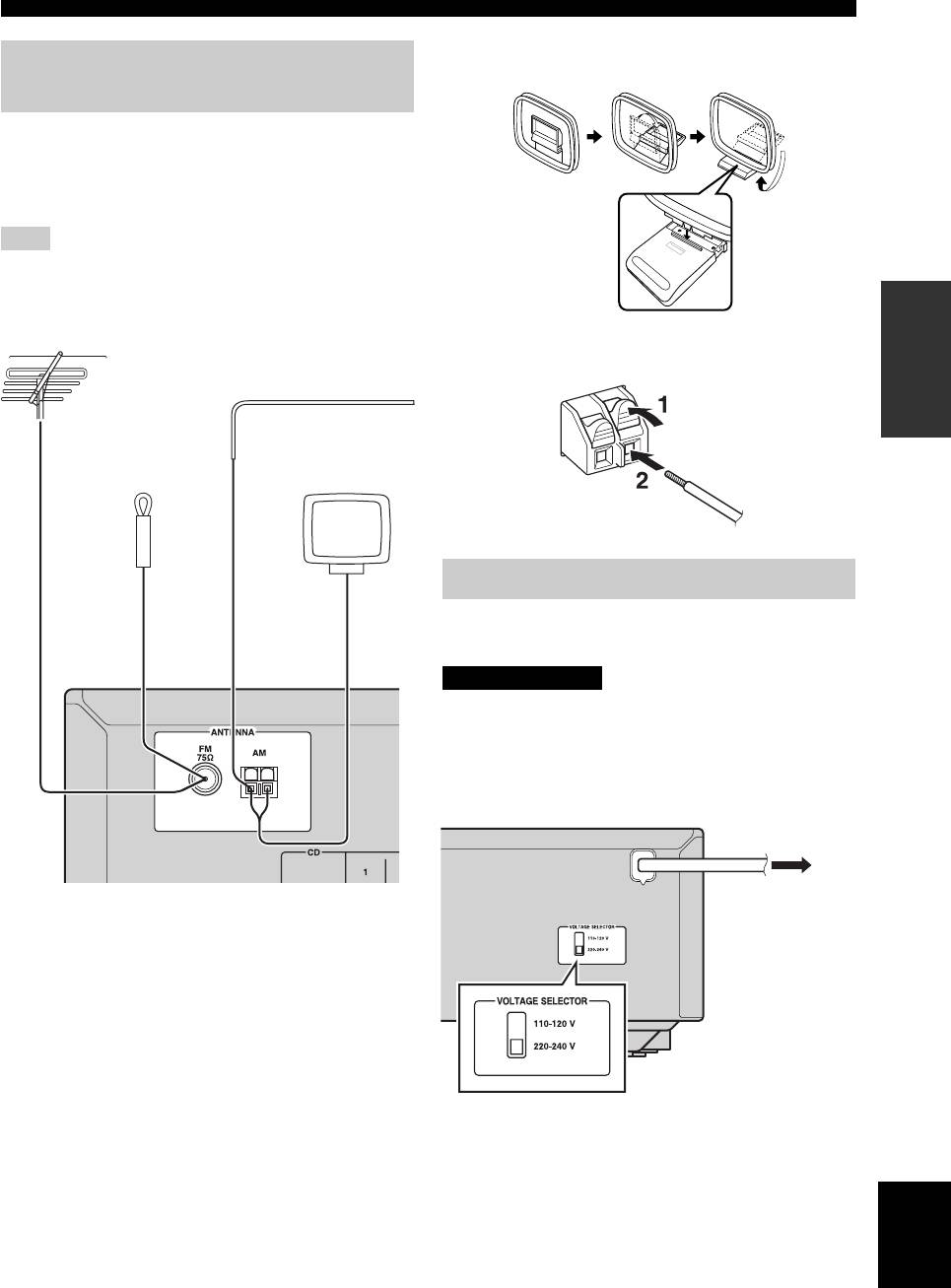
■ Assembling the supplied AM loop
Connecting the FM and AM
antenna
antennas
Indoor antennas for receiving FM and AM broadcasts are
included with this unit. In general, these antennas should
provide sufficient signal strength. Connect each antenna
correctly to the designated terminals.
Note
If you experience poor reception quality, install an outdoor
antenna. Consult the nearest authorized Yamaha dealer or service
PREPARATION
center about outdoor antennas.
Outdoor FM antenna
■ Connecting the wire of the AM loop
antenna
Outdoor AM antenna*
AM loop
antenna
(included)**
Indoor FM
antenna
(included)
Connecting power cable
Plug the power cable into an AC wall outlet after all other
connections are complete.
CAUTION
Only for General model:
Before connecting the power cable, make sure you set
VOLTAGE SELECTOR of this unit according to your
local voltage. Improper setting of VOLTAGE SELECTOR
may cause fire and damage to this unit.
To the AC wall
*Outdoor AM antenna
outlet with the
Use 5 to 10 m of vinyl-covered wire extended outdoors from a
power cable
window.
**AM loop antenna (included)
• The AM loop antenna should always be connected, even if an
outdoor AM antenna is connected to this unit.
• The AM loop antenna should be placed away from this unit.
• The wires of the AM antenna have no polarity.
English
11 En
Оглавление
- Integrated Amplifier Receiver Amplificateur Intégré Ampli-Tuner
- INTRODUCTION
- PREPARATION
- BASIC OPERATION
- ADVANCED OPERATION
- ADDITIONAL INFORMATION
- INTRODUCTION
- PRÉPARATION
- OPÉRATIONS DE BASE
- OPÉRATIONS AVANCÉES
- INFORMATIONS COMPLÉMENTAIRES
- EINFÜHRUNG
- VORBEREITUNG
- BEDIENUNG DER GRUNDFUNKTIONEN
- ERWEITERTE BEDIENUNG
- ZUSÄTZLICHE INFORMATIONEN
- INTRODUKTION
- FÖRBEREDELSE
- GRUNDLÄGGANDE ANVÄNDNING
- AVANCERAD ANVÄNDNING
- YTTERLIGARE INFORMATION
- INTRODUZIONE
- PREPARATIVI
- FUNZIONAMENTO DI BASE
- FUNZIONAMENTO AVANZATO
- INFORMAZIONI AGGIUNTIVE
- INTRODUCCIÓN
- PREPARACIÓN
- MANEJO BÁSICO
- MANEJO AVANZADO
- INFORMACIÓN ADICIONAL
- INLEIDING
- VOORBEREIDINGEN
- BASISBEDIENING
- GEAVANCEERDE BEDIENING
- AANVULLENDE INFORMATIE
- ВВЕДЕНИЕ
- ПОДГОТОВКА
- ОСНОВНЫЕ ФУНКЦИИ
- ДОПОЛНИТЕЛЬНЫЕ ФУНКЦИИ
- ДОПОЛНИТЕЛЬНАЯ ИНФОРМАЦИЯ


