Liebherr MK 63: инструкция
Раздел: Узкоспециализированное и бизнес оборудование
Тип:
Инструкция к Liebherr MK 63
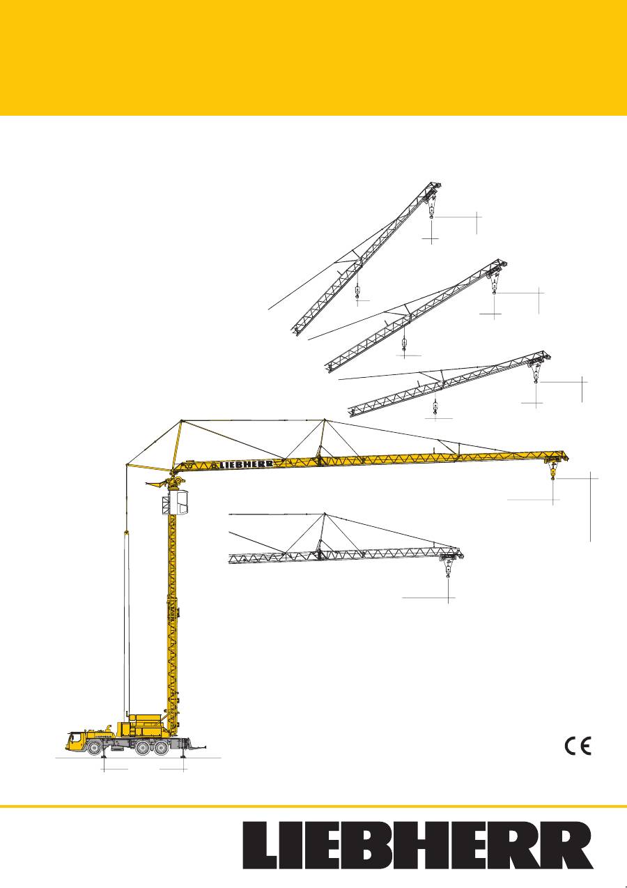
Mobilbaukran
MK
36,0 m
1800 kg
14,6
m
/
25,0
m
7,14 m
26,5 m
2850 kg
34,7 m
32,6
m
30,2
m
25,6 m
1800 kg
1800 kg
31,3 m
40,9
m
36,1
m
23,1 m
2850 kg
1800 kg
25,8 m
47,9
m
41,2
m
19,1m
1800 kg
1800 kg
45°
30°
15°
6
3
EN 14439:2009 –C25
Mobile construction crane / Grue mobile de construction
Autogrù edile / Grúa móvil de construcción
Mobiele torenkraan /
Мобильный строительный кран
2
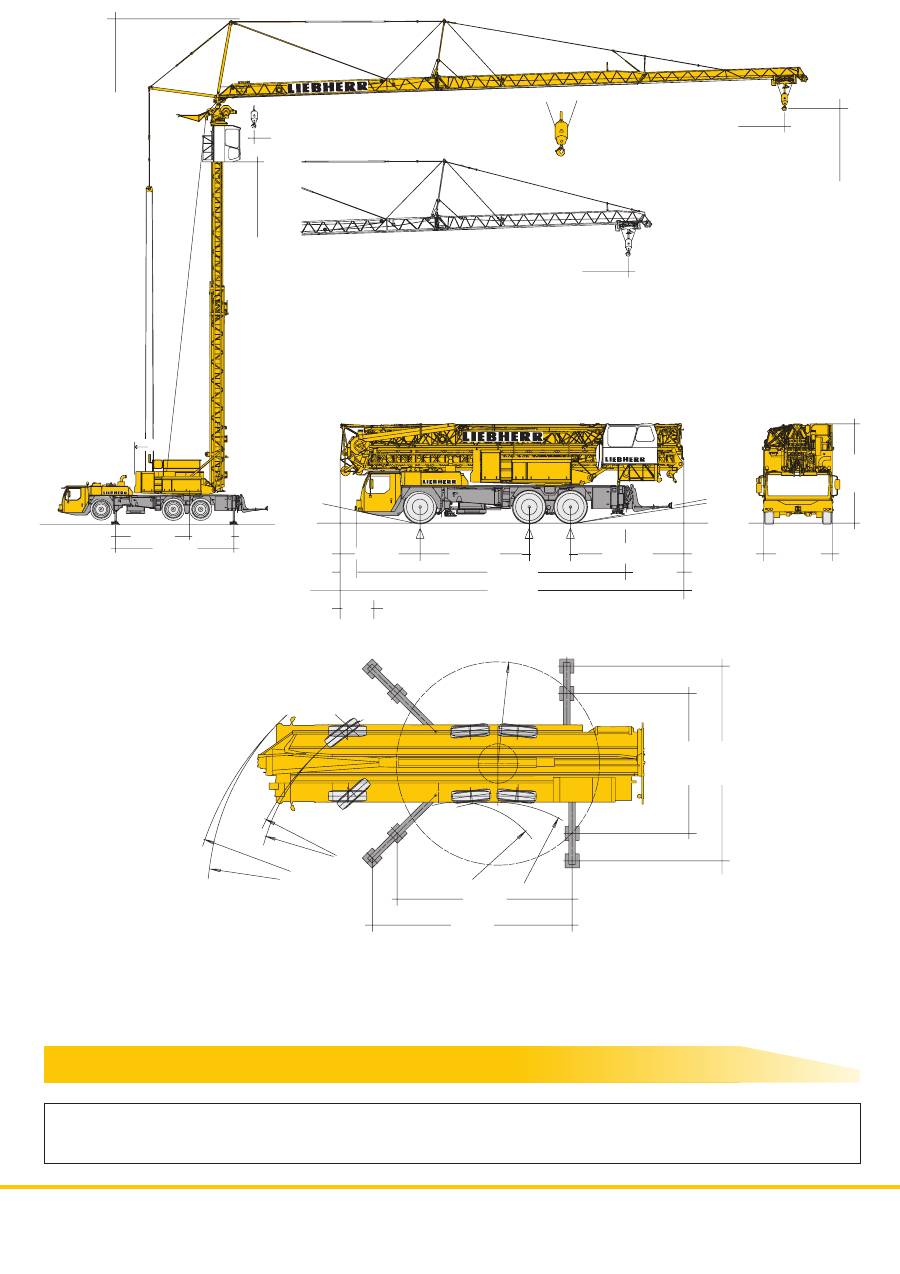
6,90
m
5,20
m
6,32 m
R =
9,12
m
7,14 m
R = 10,84
m
R = 8,83 m
R = 7,10
m
3,30
m
R
=
3,35
m
R
=
4,90
m
4,0
m
2,75 m
Permissible total weight / Poids total admissible
Peso totale ammissibile / Peso total admisible
Toegestaan totaalgewicht /
zulässiges Gesamtgewicht
Допустимый общий вес
36000 kg
26,5 m
2850 kg
36,0 m
1800 kg
14,6
m
/
25,0
m
3,5 m
22,8
m
31,2
m
4,45 m
2,69 m
7,14 m
3,3 m
3,19 m
4,355 m
1,65 m
4,535 m
10,75 m
2,33 m
13,72 m
1,5 m
0,65
m
12,0 t
12,0 t
12,0 t
12°
9°
10°
Gewicht
Weight / Poids / Peso / Peso / Gewicht /
Mасса
MK
63
max. 28,0 t
max. 28,0 t
3
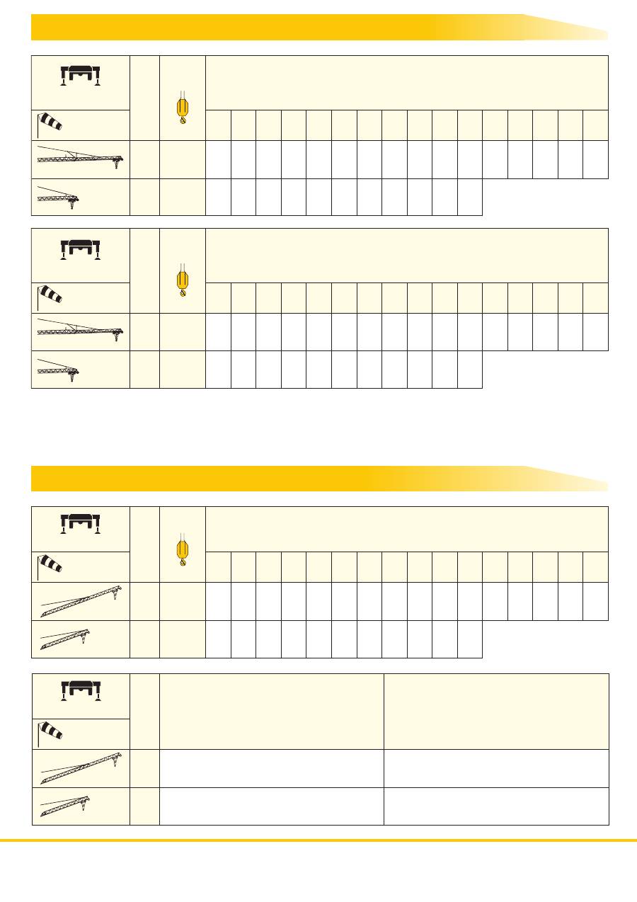
Ausladung und Tragfähigkeit
Radius and capacity / Portée et charge / Sbraccio e portata
Alcances y cargas / Vlucht en draagkracht /
Вылетигрузоподъемность
3,5 – 9,0
8000
8000 7200 5980 5090 4430
3490 3140 2860 2610 2560 2410 2220 2070 1930
9,0 10,0 12,0 14,0 16,0
20,0 22,0 24,0 26,0
26,5
28,0 30,0 32,0 34,0
36,0
m / kg
m / kg
36,0
m
26,5
3,5 – 10,0
8000
8000 8000 6610 5640 4910
3870 3490 3180 2910
2850
3,5 – 8,0
6000
6000 6000 5490 5070 4400 3870 3450 3100 2820 2570 2450 2370 2190 2030 1890
1800
7,0
8,0
9,0 10,0 12,0 14,0 16,0 18,0 20,0 22,0
23,1
24,0 26,0 28,0 30,0
31,3
m / kg
m / kg
36,0
m
26,5
3,5 – 9,5
6000
6000 6000 6000 5750 5020 4440 3970 3590 3270 2990
2850
Steep angle positions / Flèche en position relevée / Braccio inclinato
Pluma inclinada / Hoofdgiekstand /
Положение стрелы под углом
Auslegersteilstellung
7,14 m x 6,90 m
7,14 m x 6,90 m
max. 6,5 Bft
(14 m/sec.)
max. 6,5 Bft
(14 m/sec.)
36,0
m
26,5
7,14 m x 6,90 m
max. 6,5 Bft
(14 m/sec.)
3,5 – 34,7
3,5 – 25,6
m
kg
15°
1800
1800
30°
3,5 – 25,8
3,5 – 19,1
m
kg
45°
1800
1800
MK
63
1800
3910
18,0
4330
3,5 – 8,3
8000
7360 6590 5450 4630 4010
3140 2830 2570 2340 2290 2150 1990 1840 1710
9,0 10,0 12,0 14,0 16,0
20,0 22,0 24,0 26,0
26,5
28,0 30,0 32,0 34,0
36,0
m / kg
m / kg
36,0
m
26,5
3,5 – 9,4
8000
8000 7540 6230 5300 4600
3620 3260 2960 2710
2650
7,14 m x 6,90 m
max. 8,0 Bft
(20 m/sec.)
1600
3530
18,0
4050
Außer Betrieb keine Demontage notwendig.
/ Crane does not need to be disassembled
when it is not in operation. / La grue n’a pas besoin d’être démontée lorsqu’elle est mise
au repos. / Non è necessario lo smontaggio quando la gru è fuori servizio. / No es necesario
desmontar la grúa en caso de no trabajar con ella. / Indien niet in gebruik, is geen
demontage noodzakelijk /
.
Вне работы демонтаж не требуется
.
Außer Betrieb keine Demontage notwendig.
/ Crane does not need to be disassembled
when it is not in operation. / La grue n’a pas besoin d’être démontée lorsqu’elle est mise
au repos. / Non è necessario lo smontaggio quando la gru è fuori servizio. / No es necesario
desmontar la grúa en caso de no trabajar con ella. / Indien niet in gebruik, is geen
demontage noodzakelijk /
Вне работы демонтаж не требуется
.
.
4
50
37,0
111,0 m 5 x 16 mm
2
400 V
Hz
kVA
C.0.08.0063
14.00 R 25
6,7
3,9
8,3
4,8
10,8
6,2
13,2
7,7
16,7
9,7
20,5
11,9
28,2
16,3
34,7
20,1
45,0
26,1
55,4
32,1
69,8
40,5
75,0
49,8
6,6
3,8
8,1
4,7
1
2
3
4
5
6
7
8
9
10
11
12
R1
R2
km/h
km/h
38,5%
> 55,3%
%
BGL
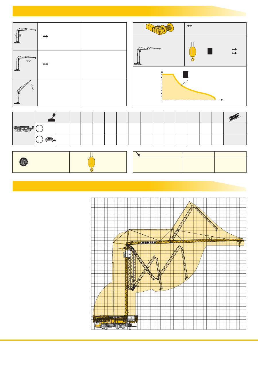
5,0 kW FU
0
1,1 U/min
4,0 kW FU
0
70,0 m/min
40 sec.
80 sec.
100 sec.
15
0 – 30°
45
0 –
°
0 –
°
24 kW FU
WIW 230 KY 005
m/min
kg
8000
500
0
16
0
75
1
m/min
0
20
40
60 70
50
30
10
0
2000
4000
6000
8000
kg
Gang
/ Speed / Vitesse
Marcia / Velocidad
Versnelling /
Передача
1
80
5
0
10
15
20
25
30
35
40
0
-5
-9
5
10
15
20
25
30
35 36 m
m
MK
63
Antriebe
Driving units / Mécanismes d entraînement /
/ Mecanismos /
’
Meccanismi
Aandrijvingen /
Приводы
Aufstellvorgang
Erection procedure / Déroulement de montage / Procedimento di montaggio
Procedimiento de montaje / Opstelling van de mobiele torenkraan /
Процесс развертывания
/ stepless / régl. continu
regl. progressiva / sin escalones / traploos
stufenlos
бесступенчатый

5
MK
63
Kranfahrgestell
Rahmen
Eigengefertigte, verwindungssteife Kastenkon-
struktion aus hochfestem Feinkorn-Baustahl.
Abstützungen
4-Punkt-Abstützung in „K“-Form, horizontal
und vertikal vollhydraulisch ausschiebbar bzw.
schwenkbar.
Bedienung von 2 Bedientabelaus beidseitig am
Fahrgestell, automatische Abstütznivellierung,
elektronische Neigungsanzeige.
Motor
D836A7, wassergekühlt, Leistung 240 kW
(326 PS) bei 2400 min
-1
, max. Drehmoment
1250 Nm bei 1200-1700 min
-1
.
Abgasemissionen entsprechend Richtlinien
97/68/EG Stufe 3 und EPA/CARB Tier 3, elekt-
ronisches Motormanagement.
Kraftstoffbehälter: 300 l.
Getriebe
ZF-12-Gang-Schaltgetriebe mit automatisier-
tem Schaltsystem AS-TRONIC. Verteilergetrie-
be, zweistufi g, mit sperrbarem Verteilerdiffe-
rential.
Achsen
Alle Achsen gelenkt und angetrieben, mit
Differentialsperren.
Federung
Alle Achsen hydropneumatisch gefedert, mit
automatischer Niveauregulierung. Federung
hydraulisch blockierbar.
Bereifung
6-fach. Reifengröße: 14.00 R 25.
Lenkung
ZF-Servocom-Hydrolenkung, 2-Kreis-Anlage
mit hydraulischer Servoeinrichtung und zusätz-
licher Reservepumpe, von der Achse angetrie-
ben.
Aktive Hinterachslenkung mit 5 elektronischen
Fahrprogrammen. 1. Achse mechanisch,
2. und 3. Achse elektrohydraulisch geschwin-
digkeitsabhängig gelenkt. Lenkung entspre-
chend EG-Richtlinie 70/311/EWG.
Bremsen
Betriebsbremse: Allrad-Servo-Druckluftbremse,
alle Achsen sind mit Scheibenbremsen ausge-
stattet, 2-Kreis-Anlage.
Handbremse: Federspeicher auf die Räder der
2. und 3. Achse wirkend.
Dauerbremse: Auspuffklappenbremse mit
Liebherr Zusatzbremssystem.
ABV-Automatischer-Blockier-Verhinderer in
Verbindung mit ASR-Antischlupfregelung.
Bremsen entsprechend EG-Richtlinien
71/320 EWG.
Fahrerhaus
Großräumige Kabine in Stahlblechausführung,
korrosionsbeständig durch Kataphorese-
Tauchgrundierung, gummielastisch aufgehängt
und hydraulisch gedämpft, schall- und wärme-
dämmende Innenverkleidung nach EG-Richtli-
nie, Sicherheitsverglasung, Bedien- und Kont-
rollinstrumente, Komfortausstattung, mit freier
Sicht auf die Straße.
Elektrische Anlage
Steuerung der elektrischen und elektronischen
Komponenten mit modernster Datenbus-Tech-
nik, 24 Volt Gleichstrom, 2 Batterien je 170 Ah,
Beleuchtung nach StVZO.
Ausstattung
Zusatzheizung Fahrerhaus.
Kranoberwagen
Drehbühne
Drehbühne als Stahlblechkonstruktion ausge-
führt mit Turmlagerung und Verbindung zum
Kugeldrehkranz. Als Verbindungselement zum
Kranfahrgestell dient ein Liebherr-Kugeldreh-
kranz mit Innenverzahnung; Drehbühnenverrie-
gelung zum Unterwagen.
Stromversorgung
Dieselstromaggregat 48,0 kVA. Eigener Ober-
wagentank; alternativ Stromversorgung über
Baustellenstrom (Fremdstromanschluß 63 A /
400 V); Stromverteiler 1 x 32 A, 2 x 16 A,
3 x Schuko 220 V.
FU-Hubwerk
Hubwerksantrieb mit zwei Trommeln für Mon-
tage und Hubbetrieb. Der Antrieb mit Fre-
quenzumrichter-Steuerung bietet stufenlose
Hub- und Senkgeschwindigkeit, mit Feinpositi-
oniermodus.
FU-Drehwerk
Stufenlos einstellbare Arbeitsgeschwindigkei-
ten, elektronische Windlastregelung und auto-
matische Lastpendeldämpfung. Es ist konterfä-
hig und kontersicher mit individuell einstellbarer
Drehzahl-Drehmomentsteuerung.
Katzfahrwerk
Katzfahrwerkantrieb mit Frequenzumrichter
und stufenlos verstellbaren Geschwindigkeiten.
Schaltanlage
Elektrische Anlage mit speicherprogrammier-
barer Steuerung (SPS).
Telekopturm
Teleskopturm in Fachwerk-Konstruktion mit
Turmverriegelung zur Drehbühne.
Ausleger
Dreigeteilter Ausleger, sehr enger hoher Ver-
lauf der Auslegerluftmontagekurve, so dass
nur wenig Aufstellraum erforderlich ist. Die
Luftmontage erfolgt durch eine separate
Winde und Zuschaltung einer Auslegermon-
tagewinde.
Die Abspannung des Auslegers erfolgt über
Teleskopstangen bzw. über Abspannseile.
Hydraulische Auslegerschwenkvorrichtung
(Option).
Katzfahrseil- und
Hubseilspannung
Während des Montage- und Demontagevor-
ganges wird sowohl das Hubseil als auch das
Katzfahrseil automatisch gespannt.
Liftkabine
Vollsichtführerhaus als Liftkabine ausgeführt,
stufenlos höhenverstellbar mit eigenem Antrieb
und mit Rundum-Sicherheitsverglasung. Kran-
führersessel mit integrierten Meisterschaltern
in den Armlehnen, mit Warm- und Kaltluft-An-
lage über Thermostat geregelt, mit Führerhaus-
beleuchtung und Scheibenwisch- und Wasch-
anlage. Elektronisches Monitor-System EMS.
220 V Steckdose
Verfahren des Krans
im aufgerichteten
Zustand
Durch die sehr günstige Schwerpunktlage ist
es möglich, diesen Kran im aufgerichteten Zu-
stand zu verfahren.
0°- 15°- 30°- 45°
Auslegerstellung
Serienmäßige Auslegerstellungen, über Verkür-
zung der hinteren Abspannung, aus dem Be-
triebszustand, per Funkfernsteuerung oder aus
der Liftkabine heraus möglich.
Ausstattung
Ausrüstung für Baustellenbeleuchtung:
4 x 1500W Halogenscheinwerfer.
Zusatzausrüstungen
Zusatzausrüstungen wie zum Beispiel TELMA,
Sonderlackierung etc., siehe Preisliste bzw.
Angebot.
6-Zylinder-Diesel, Fabrikat Liebherr, Typ

6
MK
63
Crane carrier
Frame
Liebherr designed and manufactured, box
type, torsion resistant design of high-tensile
fi ne grained structural steel.
Outriggers
4-point support in “K” shape, all-hydraulic
horizontal and vertical operation with 2 control
panels on either side of the crane carrier, au-
tomatic outrigger levelling, electronic inclina-
tion display.
Engine
Liebherr, type D836A7, water-cooled,
240 kW (326 HP) at 2400 min
-1
, max. torque
1250 Nm at 1200-1700 min
-1
.
Exhaust emissions acc. to 97/68/EC stage 3
and EPA/CARB Tier 3, electronic engine man-
agement.
Fuel tank capacity: 300 l.
Transmission
ZF 12-speed gear box with automatic control
system AS-TRONIC. Two-stage transfer case
with lockable transfer differential.
Axles
All axles steered, driven with differential locks.
Suspension
All axles with hydropneumatic suspension, au-
tomatic levelling and hydraulic locking facility.
Tyres
6 tyres. Tyre size: 14.00 R 25.
Steering
ZF Servocom hydraulic power steering, dual
circuit system with hydraulic servo system and
auxiliary pump circuit, driven by the axle.
Active rear-axle steering with 5 electronic trav-
elling programmes. 1
st
axle steered mechani-
cally and 2
nd
and 3
rd
axle steered electrohydrau-
lically depending on speed. Steering system
acc. to EC directive 70/311/EEC.
Brakes
Service brake: all-wheel servo-air brake, all ax-
les are equipped with disc brakes, dual circuit.
Hand brake: Spring-loaded, acting on all
wheels of axles 2 and 3.
Sustained-action brake: Exhaust retarder with
additional Liebherr braking system.
Anti-lock device in conjunction with anti skid
control.
Brakes acc. to EC directive 71/320 EEC.
Driver’s cab
Spacious, steel made, corrosion resistant cab,
cataphoretic dip-primed, on resilient suspen-
sion with hydraulic shock absorbers, sound
and heat absorbing internal panelling acc. to
EC directive, safety glazing, operating and
control instruments, comfortably equipped
with unobstructed view of the road.
Electrical system
Control of the electrical and electronical com-
ponents by modern data bus technique.
24 Volt DC, 2 batteries 170 Ah each, lighting
according to traffi c regulations.
Equipment
Additional heating in the driver’s cab.
Crane superstructure
Slewing platform
Steel-plate structure including tower pivot
bearing and connection to slewing ring. Con-
nection element to crane carrier is a Liebherr
slewing ring with internal toothing. Slewing
platform interlocking to undercarriage.
Power supply
48.0 kVA diesel-powered generator, tank on
superstructure; alternatively power supply via
building site main cabinet (external current
connection 63 A / 400 V); power distributor
1 x 32 A, 2 x 16 A, 3 x earthed sockets 220 V.
FC hoist gear
Drives two drums, one for assembly and one
for hoisting. Continuous frequency-convert-
er control provides continuously variable hoist-
ing and lowering speeds, with precision posi-
tioning mode.
FC slewing gear
Continuously variable operating speed, elec-
tronic wind load control and automatic load os-
cillation damping. Counter-current can be ap-
plied in absolute safety. Individually
adjustable rotational speed and torque control.
Trolley travel gear
Trolley travel gear with frequency converter
and continuously variable speed.
Switchgear
Programmable logic control system (PLC).
Telescopic tower
Telescopic tower of lattice construction with
tower lock to slewing platform.
Jib
Three-section jib, very high overhead assembly
curve so that only little space is needed for
erecting. Assembly takes place with a separate
winch and by engaging the jib assembly winch.
The jib is guyed by telescopic rods or cables.
Hydraulic jib slewing device (option).
Tensioning of trolley
and hoist ropes
During the assembly and disassembly
processes the hoist and trolley ropes are
tensioned automatically.
Elevating cabin
The operator’s cabin with its 360° view is of
elevating pattern with safety glass windows all
round and its own drive system for stepless
height adjustment.
Crane operator’s seat with the master switches
integrated into the armrests, thermostat-
controlled heating and ventilation, lighting and
a window wash/wipe system.
Electronic monitoring system EMS.
220 V socket.
Transport of crane
in erected position
A very favourable centre of gravity permits
transport of the crane in its erected position.
0°- 15°- 30°- 45°
jib position
Standard jib positions achieved by shortening
the rear jib guying, possible when the crane
is in operating condition, via radio remote
control or from the elevating cabin.
Equipment
Equipment for construction site lighting:
4 x 1500 W halogen lights.
Additional equipment
For additional equipment such as TELMA,
special paint fi nishes, etc., see price list or
offer.
6-cylinder Diesel engine, manufactured by

7
MK
63
Châssis-porteur
Châssis
Fabrication Liebherr, construction en caisson
indéformable, en acier à haute résistance à
grains fi ns.
Stabilisateurs
Calage en 4 points en «K», à télescopage hori-
zontal et vérinage vertical entièrement hydrau-
liques avec 2 tableaux de commande disposés
de chaque côté du véhicule, mise à niveau
automatique des stabilisateurs, indicateur
électronique d’angle d’inclinaison.
Moteur
D836A7, refroidi par eau, puissance 240 kW
(326 ch) à 2400 min
-1
, couple max. 1250 Nm
à 1200-1700 min
-1
.
Emissions des gaz d’échappement conformes
aux directives 97/68/CE phase 3 et EPA/CARB
Tier 3, gestion électronique du moteur.
Capacité du réservoir à carburant: 300 l.
Boîte de vitesse
Boîte de vitesses ZF à 12 rapports, mécanis-
me automatisé à commande AS-TRONIC.
Boîte de transfert à 2 étages avec blocage
de différentiel.
Essieux
Tous les essieux sont directeurs, moteurs à
blocage de différentiel.
Suspension
Tous les essieux à suspension hydropneuma-
tique, avec réglage de niveau et blocables
hydrauliquement.
Pneumatiques
6 pneumatiques. Taille: 14.00 R 25.
Direction
Direction hydraulique ZF Servocom, à deux
circuits, assistée hydrauliquement, avec
pompe auxiliaire entraînée par essieu. Direction
de l’essieu arrière active avec 5 programmes
de conduite. Essieu 1 dirigé mécaniquement et
essieux 2 et 3 dirigés électrohydrauliquement
en fonction de la vitesse. Direction conforme
à la directive européenne CE 70/311/CEE.
Freins
Freins de service: servofrein à air comprimé,
tous les essieux sont munis de freins à disque,
à 2 circuits. Frein à main: par cylindres à res-
sorts, agissant sur les roues des essieux 2 et 3.
Frein à régime continu: Ralentisseur sur échap-
pement avec système de freinage additionnel
Liebherr. Dispositif anti-enrayeur avec contrôle
antipatinage.
Freins selon directive CE 71/320 CEE.
Cabine de conduite
Cabine spacieuse en tôle d’acier, traitement
anticorrosion, par bain de cataphorèse, avec
suspension élastique et amortisseurs hydrau-
liques, revêtement intérieur avec isolation pho-
nique et thermique selon les directives eu-
ropéennes, glaces de sécurité, appareils de
commande et de contrôle, équipement con-
fortable avec vue dégagée sur la chaussée.
Installation
électrique
Composants électriques et électroniques
reliés entre eux par bus de données moderne.
Courant continu 24 Volts, 2 batteries à 170 Ah
chacune, éclairage conforme au code de la
route.
Equipement
Chauffage additionnel dans la cabine de
conduite.
Partie tournante
Plate-forme
tournante
Plate-forme tournante réalisée en tôles d’acier
avec support pour mât et liaison avec la cou-
ronne d’orientation à billes.
La liaison avec le châssis-porteur est assurée
par une couronne d’orientation Liebherr avec
denture intérieure. Verrouillage de la plate-
forme tournante au châssis.
Alimentation
en courant
Groupe électrogène diesel 48,0 kVA, réservoir
sur partie tournante; alternativement alimen-
tation en courant par armoire de chantier (rac-
cordement extérieur 63 A / 400 V); distributeur
de courant 1 x 32 A, 2 x 16 A, 3 x prises à con-
tact de protection 220 V.
Mécanisme
de levage CF
Mécanisme de levage avec deux tambours
pour le montage et le levage. Ce mécanisme
à pilotage par changeur de fréquence offre
des vitesses réglables en continu en montée
et descente et un mode de positionnement.
Mécanisme
d’orientation CF
Vitesses de travail réglables en continu,
contrôle électronique de l’action du vent et
amortissement automatique du ballant de la
charge.
Freinage par amorçage du mouvement inverse
possible et sûr. Asservissement en vitesse et
en couple réglable individuellement.
Mécanisme
de distribution
Mécanisme de distribution avec changeur de
fréquence et vitesses variables en continu.
Installation
électrique
Installation électrique avec commande
programmable à mémoire (CPM).
Mât télescopique
Mât télescopique en treillis avec verrouillage
du mât sur la plate-forme tournante.
Flèche
Flèche en trois éléments, montage en l’air de
la fl èche s’inscrivant dans une courbe très
étroite et ne nécessitant donc qu’un espace
restreint. Montage en l’air au moyen d’un treuil
séparé et par enclenchement d’un treuil de
montage de la fl èche. La suspension de la
fl èche est obtenue au moyen de tirants télesco-
piques et de câbles de suspension. Dispositif
d’orientation hydraulique de la fl eche (option).
Tension du câble
de distribution et
du câble de levage
Pendant les opérations de montage et de dé-
montage, le câble de levage ainsi que le câble
de distribution sont tendus automatiquement.
Cabine élévatrice
Cabine panoramique à hauteur réglable en
continu, avec moteur indépendant et vitrage
de sécurité à visibilité totale. Siège de grutier
avec combinateurs intégrés dans les accou-
doirs, installation air chaud-air froid à régula-
tion thermostatique, éclairage de cabine et es-
suie-glace/lave-glace. Système électronique à
moniteur EMS. Prise 220 V.
Déplacement de
la grue en position
dépliée
Grâce à son centre de gravité très favorable,
cette grue peut translater en position dépliée.
Inclinaison de la
fl èche à 0°-15°-
30°-45°
Les positions de fl èche fournies de série sont
obtenues par raccourcissement de la sus-
pension arrière de la fl èche et sont possible
lorsque la grue est en mode de fonctionne-
ment, à partir de la radiocommande ou de la
cabine élévatrice.
Equipement
Equipement pour éclairage chantier:
4 projecteurs halogènes à 1500 W chacun.
Equipements supplémentaires
Equipements complémentaires, comme p. ex.
TELMA, peinture spéciale, etc., voir notre liste
de prix ou offre.
Diesel, 6 cylindres, marque Liebherr, type

8
MK
63
Autotelaio
Telaio
Produzione Liebherr, struttura di tipo scatolato
antitorsione in acciaio a grana fi ne ad elevato
grado di snervamento.
Stabilizzatori
4 stabilizzatori, estraibili in formato „K“, oriz-
zontale e verticale, in modo completamente
idraulico come anche la rotazione dello stabi-
lizzatore. Sistema di comando situato nei pan-
nelli ai lati del carro, livellamento automatico.
Indicazione elettronica dell’inclinazione.
Motore
D836A7, raffreddato ad acqua, potenza
240 KW (326 CV) a 2400 min
-1
, coppia massi-
ma 1250 Nm con 1200-1700 min
-1
.
Emissioni gas di scarico conformi alle direttive
97/68/CE, parte3eEPA/CARB Tier 3.
Capacità del serbatoio carburante: 300 l.
Cambio
Cambio ZF a 12 marce con sistema di com-
mutazione automatico AS-Tronic.
Ripartitore a due stadi, con bloccaggio diffe-
renziale.
Assi
Tutti gli assi sterzanti etraenti, con bloccaggio
differenziale.
Sospensioni
Tutti gli assi a sospensione idropneumatica a
regolazione automatica e bloccabili idraulica-
mente.
Pneumatici
6 pneumatici. Dimensione 14.00 R 25.
Sterzo
Sterzo ZF-Hydro-SERVOCOM a doppio circu-
ito con servosterzo idraulico e pompa addizio-
nale di riserva, azionata dall’asse.
Sterzo attivo con 5 programmi elettronici.
1° asse sterzato meccanicamente, 2° e 3°
asse sterzati elettro-idraulicamente in base
alla velocità.
In accordo con le normative CE 70/311 EWG.
Freni
Freno di servizio: pneumatico servoassistito
su tutte le ruote, tutti gli assi sono equipaggiati
con freni a disco a doppio circuito.
Freno a mano: accumulatore a molla agente
sulle ruote del 2° e 3° asse.
Freni addizionale: valvola agente su impianto
di scarico.
Sistema antibloccaggio (ABS) con regolatore
antislittamento (ASR). Freni conformi alle diret-
tive CE 71/320 EWG.
Cabina di guida
Cabina spaziosa in lamiera d’acciaio, prote-
zione anticorrosione zincata per cataforesi, a
sospensione elastica e ammortizzata idrauli-
camente; rivestimento interno con isolamen-
to acustico e termico, conforme alla normativa
CE. Vetratura di sicurezza; strumenti di coman-
do e controllo, dotazione comfort e ottima visi-
bilità della strada.
Impianto elettrico
Controllo dei componenti elettrici ed elettroni-
ci mediante trasmissione comandi via “data
bus”, corrente continua 24V, 2 batterie da
170 Ah ciascuna, impianto illuminazione con-
forme al codice della strada.
Equipaggiamento
Riscaldamento aggiuntivo cabina di guida.
Torretta
Piattaforma girevole
Piattaforma girevole realizzata in lamiera d’ac-
ciaio, per il supporto torre e alloggiamento ral-
la. L’elemento di giunzione con il telaio del car-
ro è la ralla Liebherr a dentatura interna;
bloccaggio della piattaforma girevole al carro.
Alimentazione
corrente
Generatore Diesel da 48,0 kVA. Serbatoio tor-
retta indipendente; alimentazione esterna me-
diante corrente del cantiere (allacciamento
elettrico esterno 63 A / 400 V); quadro di ri-
partizione con 1 x 32 A, 2 x 16 A, 3 x Schu-
ko 220 V.
Argano di solleva-
mento con converti-
tore di frequenza
Argano di sollevamento con due tamburi per
sollevamento e montaggio. Questo meccani-
smo con comando a convertitore di frequen-
za offre velocità di salita e discesa progressive,
con sistema di posizionamento preciso.
Gruppo di rotazione
con convertitore di
frequenza
Velocità di lavoro progressive regolabili, regola-
zione elettronica del carico esposto al vento
e dispositivo antipendolio automatico.
Tramite un sistema di regolazione elettronica
del numero giri e del momento è possibile ef-
fettuare una contromanovra utilizzabile in lavo-
ro come in caso di sicurezza.
Meccanismo di
traslazione carrello
Gruppo di traslazione carrello con convertitore
di frequenza e velocità di traslazione regolabili
progressivamente.
Impianto elettrico
Impianto elettrico con sistema di comando
programmabile (PLC).
Torre telescopica
Torre telescopica con struttura tralicciata. Bloc-
caggio tra torre e piattaforma girevole.
Braccio
Braccio in 3 sezioni, curva di montaggio aerea
in spazio ridotto, per un ingombro a terra mini-
mo. Il montaggio aereo avviene tramite un ver-
ricello ausiliario separato e il meccanismo di
montaggio del braccio.
Il tirante del braccio è costituito da aste tele-
scopiche o tiranti a fune. Ribaltamento del
braccio da trasporto a lavoro con sistema
idraulico (opzionale).
Tensione fune
sollevamento e
traslazione carrello
Durante il montaggio e lo smontaggio le funi
di sollevamento e traslazione carrello sono
tese automaticamente.
Cabina ascensore
Cabina ascensore con centratura panoramica
di sicurezza, regolazione progressiva in altezza
con azionamento indipendente. Sedile opera-
tore con comandi integrati nei braccioli, im-
pianto di climatizzazione a controllo termo-
statico con impianto di illuminazione cabina e
impianto lavatergicristallo. Sistema di monito-
raggio elettronico EMS. Presa 220 V.
Traslazione gru
in posizione eretta
La posizione molto vantaggiosa rispetto al
baricentro permette di traslare con la gru in
assetto di lavoro.
Posizione impennata
del braccio a
0° - 15° - 30° - 45°
Queste posizioni del braccio di serie, tramite
accorciamento del tirante di ancoraggio, pos-
sono essere effettuate direttamente dai co-
mandi posti in cabina o dal radiocomando.
Equipaggiamento
Equipaggiamento illuminazione cantiere:
4 x 1500 W con lampade alogene.
Equipaggiamenti aggiuntivi
Equipaggiamenti addizionali come ad es.
TELMA, verniciatura speciale, etc, consultare
listino o offerta.
Diesel a 6 cilindri in linea, marca Liebherr, tipo

9
MK
63
Chasis
Bastidor
Fabricación propia en acero estructural de
grano fi no de alta resistencia, resistente a la
torsión, tipo cajón.
Estabilizadores
4 puntos de apoyo, en forma de “K”, con
movilidad horizontal y vertical o giratoria total-
mente hidráulica.
Control a través de dos botoneras en ambos
lados del chasis, nivelación de apoyos com-
pletamente automática, indicador de inclina-
ción electrónico.
Motor
D836A7, refrigerado por agua, 240 kW
(326 PS) a 2400 min
-1
, par de giro máx.
1250 Nm a –1200-1700 min
-1
.
Cumple la actual normativa en cuanto a emi-
sión de substancias 97/68/EG Stufe 3 und
EPA/CARB Tier 3, Gestión electrónica del
motor.
Capacidad del depósito de combustible: 300 l.
Transmisión
Cambio ZF de 12 velocidades con cambio
automático AS-Tronic. Caja tránsfer de dos
escalonamientos, con diferencial bloqueable.
Ejes
Todos los ejes son direccionables con bloqueo
transversal del diferencial.
Suspensión
Todos los ejes con suspensión hidroneumática,
con regulación automática de nivel.
Suspensión con bloqueo hidraúlico.
Cubiertas
6 cubiertas de tamaño: 14.00 R 25.
Dirección
Dirección hidráulica ZF Servocom, sistema de
dos circuitos con dirección asistida hidráulica
y una bomba de reserva adicional, activada
a través del eje. Dirección trasera activa con
5 programas de traslación.
1. eje mecánico, 2. y 3. eje electrohidráulico
dependiendo de la velocidad direccionable.
Dirección según directivas de la CEE 70/311
CEE.
Frenos
Freno de servicio: servofreno neumático con
actuación a todas las ruedas, todos los ejes
están equipados con frenos de discos, sis-
tema de dos circuitos hidraúlicos. Freno de
mano: por acumuladores de muelle con ac-
tuación a las ruedas de los ejes 2 y 3.
Frenos continuos: freno motor con sistema de
freno adicional Liebherr ZBS. Antibloqueo au-
tomático ABV con antideslizante ASR.
Frenos según directivas de la CEE 71/320 CEE.
Cabina
Cabina espaciosa fabricada en chapa de acero
galvanizado, resistente a la corrosión mediante
imprimación cateforética por inmersión, con
suspensión elástica y amortiguación hidráulica,
revestimiento interior de aislante térmico y
acústico según directivas de la CEE, acristala-
miento de seguridad, instrumentos de mando
y control, equipamiento de gran comodidad,
con plena vista a la carretera.
Sistema eléctrico
Pilotaje de los componentes eléctricos y elec-
trónicos con moderna tecnología de bus de
datos, 24 V corriente continua, 2 baterías con
170 Ah cada una, alumbrado según código de
permiso de circulación.
Equipamiento
Calefacción adicional independiente del motor
en la cabina de camión.
Superestructura
Superestructura
Construcción fabricada en acero; el elemento
de union es una corona de giro de rodillos
fabricados por Liebherr con dentado interior.
Bloqueado de superestructura con chasis
inferior.
Suministro
de corriente
Agregado Diesel 48,0 kVA.
Deposito propio para superestructura,
alternativamente abastecimiento de corriente
externa. (abastecimiento externo 63 A / 400 V);
Repartidor de corriente1 x 32 A, 2 x 16A,
3 x Schuko 220 V.
Cabrestante FU
Tracción de cabrestante con 2 tambores para
montaje y servicio de pasteca. Este mecanis-
mo de pilotaje con cambiador de frecuencia
ofrece gama de velocidades regulables conti-
nuas en elevación y descenso, con modo de
posicionamiento sensible.
Mecanismo
de giro FU
Velocidades de trabajo regulables sin escalo-
namientos, control electrónico del impacto del
viento sobre la carga y amortiguador automáti-
co de la oscilación de carga.
Carro
Tracción del carro con cambiador de frecuen-
cia y velocidades regulables sin escalonamien-
tos.
Instalación eléctrica
Instalación eléctrica con pilotaje a través de
memoria de programa (SPS).
Torre telescópica
Torre telescópica en construcción de celosía
con bloqueo de torre a superestructura.
Pluma
Pluma con 3 tramos, con alto recorrido de
curva de montaje de pluma suspendida,
escaso espacio necesario para su montaje.
El montaje con pluma suspendida se realiza
a través de un cabrestante adicional y co-
nexión de un cabrestante para montaje de la
misma. La sujeción de la pluma se efectua a
través de tirantes telescópicos o bien a través
de tensores.
Dispositivo hidráulico de giro de pluma (opcio-
nal).
Cable para tras-
lación de carro
y tensor del cable
de elevación
Durante el montaje y desmontaje se tensan el
cable de elevación y el cable de traslación de
carro automáticamente.
Cabina – ascensor
Cabina panorámica, regulable sin escalona-
mientos con tracción propia y con acristala-
miento panorámico de seguridad.
Asiento de conductor con joystick integrado
en apoyabrazos, sistema de aire frio y calien-
te regulado a través de termostato, iluminación
de cabina y limpiaparabrisas.
Desplazamiento con
pluma desplegada
Gracias al centro de gravedad muy favorable
es posible desplazar la grúa con pluma des-
plegada.
Inclinación de pluma
0° - 15° - 30° - 45°
Inclinación de pluma en serie, posible en
estado de funcionamiento de la grúa, a
través de mando control o desde la cabina.
Equipamiento
Equipamiento para iluminación en obra:
4 x 1500 W focos halógenos.
Equipamiento adicional
Equipamiento adicional como por ejemplo
TELMA, pintura especial etc, véase tarifa o
oferta.
Diesel con 6 cilindros, marca Liebherr, tipo

10
MK
63
Kraanonderwagen
Chassis
Zelfvervaardigde, buigstijve kastconstructie
van zeer sterk fi jnkorrelig bouwstaal.
Onderstempeling
4-punts onderstempeling in „K“-vorm, horizon-
taal en verticaal volhydraulisch uitschuifbaar
resp. zwenkbaar.
Bediening via 2 bedieningspanelen aan weers-
kanten van de onderwagen, automatische
stempelnivellering, elektronische weergave
van de scheefstand.
Motor
D836A7, watergekoeld, vermogen 240 kW
(326 PS) bij 2400 min
-1
, max. koppel 1250 Nm
bij 1200-1700 min
-1
.
Uitlaatgasemissies volgens richtlijn 97/68/EG
deel 3 en EPA/CARB tier 3, elektronisch mo-
tormanagement.
Brandstoftank: 300 l.
Versnellingsbak
ZF-schakelbak met 12 versnellingen met ge-
automatiseerd schakelsysteem AS-TRONIC.
Verdeelbak, twee standen, met blokkeerbaar
differentiëel.
Assen
Alle assen gestuurd en aangedreven, met
differentiëelblokkeringen.
Vering
Alle assen zijn hydropneumatisch geveerd met
automatische niveauregeling. Vering hydrau-
lisch te blokkeren.
Banden
6 stuks. Bandenmaat: 14.00 R 25.
Stuurmechanisme
ZF-Servocom hydraulische sturing, 2 circuits
met hydraulische stuurbekrachtiging en extra
reservepomp, door de as aangedreven.
Actieve achterasbesturing met 5 elektronische
rijprogramma´s. 1
e
as mechanisch 2
e
en 3
e
as
elektrohydraulisch snelheidsafhankelijk ge-
stuurd. Sturing volgens EG-richtlijnen 70/311/
EWG.
Remmen
Gewone rem: Servo-persluchtremmen op alle
wielen, alle assen zijn met schijfremmen uitge-
rust, met 2 circuits.
Handrem: Verende buffers op de wielen van de
2
e
en 3
e
as werkend.
Continu-rem: Rem op de uitlaatklep met extra
remsysteem van Liebherr.
ABS-Automatisch antiblokkeersysteem samen
met ASR-antislipregeling. Remmen volgens
EG-richtlijnen 71/320 EWG.
Cabine
Ruime cabine in staalplaatuitvoering, corrosie-
bestendig door elektroforese-voorbehandeling,
met rubber elastisch opgehangen en hy-
draulisch gedempt, geluids-en warmte-isole-
rende binnenbekleding volgens EG-richtlijn,
veiligheidsglas, bedienings-en controle-instru-
menten, comfortabele uitvoering, met vrij zicht
op de weg.
Elektrische
installatie
Besturing van de elektrische en elektronische
componenten met de modernste databus-
techniek, 24 Volt gelijkstroom, 2 accu´s elk
170 Ah, verlichting volgens StVZO.
Uitvoering
Bijverwarming cabine.
Kraanbovenwagen
Draaiplateau
Draaiplateau als staalplaatconstructie uitge-
voerd met lagering voor het opstaande gedeel-
te en verbinding met de kogeldraaikrans. Als
verbindingselement met de kraanonderwagen
dient een Liebherr-kogeldraaikrans met inwen-
dige vertanding; vergrendeling van het draai-
plateau met de onderwagen.
Stroomvoorziening
Dieselstroomaggregaat 48,0 kVA.
Een tank zit op de bovenwagen; een alternatief
is stroomvoorziening via een aansluiting op de
bouwplaats (externe stroomaansluiting
63 A / 400 V); stroomverdeler 1 x 32 A,
2 x 16 A, 3 x Schuko 220 V.
FU-hijswerk
Hijswerkaandrijving met twee trommels voor
montage en hijsfunctie. De aandrijving met
frequentieomvormer-besturing biedt traploze
op-en afl iersnelheid, met modus om subtiel te
positioneren.
FU-draaiwerk
Traploos instelbare werksnelheden, elektroni-
sche windbelastingsregeling en automatisch
dempen van de schommelingen van de last.
Tegendraaien is mogelijk en vindt plaats met
apart instelbare besturing van het toerental en
het koppel.
Katrijwerk
Aandrijving katrijwerk met frequentie-omvormer
en traploos verstelbare snelheden.
Schakelsysteem
Elektrische installatie met geheugenprogram-
meerbare besturing (SPS).
Telescopeerbare
toren
Telescopeerbare toren met vakwerk-construc-
tie met vergrendeling van de toren aan het
draaiplateau.
Giek
3-delige giek, zeer smal verloop van de monta-
gecurve in de hoogte, zodat maar weinig ruim-
te voor het opstellen vereist is. De montage in
de hoogte vindt plaats door een aparte lier en
het erbij aanzetten van een giekmontagelier.
De afspanning van de giek vindt plaats met
telescoopstangen of via spankabels. Hydrauli-
sche mechanisme voor het draaien van de
giek (optie).
Spannen van de
katrijkabel en de
hijskabel
Tijdens de montage- en demontageprocedure
worden zowel de hijskabel als de katrijkabel
automatisch gespannen.
Liftcabine
Cabine met volledig zicht als liftcabine uitge-
voerd, traploos in hoogte verstelbaar met ei-
gen aandrijving en met veiligheidsglas rondom.
Stoel van de kraanmachinist met in de armleu-
ningen zittende commando-schakelaars, met
via thermostaat geregelde verwarming/aircon-
ditioner, met cabineverlichting en ruitenwisser/
ruitensproeier.
Elektronisch Monitoring Systeem EMS.
220 V stekkerdoos.
Verplaatsen van de
kraan in opgerichte
toestand
Door de zeer gunstige ligging van het zwaarte-
punt is het mogelijk om deze kraan in opge-
richte toestand te verplaatsen.
Giek in de standen
0°-15°-30°-45°
Standaard giekstanden, door het verkorten van
de afspanning achter, vanuit de werkstand van
de kraan, besturing via afstandsbediening of
vanuit de liftcabine mogelijk.
Uitvoering
Uitrusting voor het verlichten van de bouw-
plaats: 4 x 1500 W halogeen schijnwerpers.
Extra uitrusting
Extra uitrusting, zoals bijvoorbeeld TELMA,
speciaal spuitwerk enz., zie prijslijst of offerte.
6-cilinder diesel, fabricaat Liebherr, type

11
MK
63
Шасси крана
Рама
Жесткая
конструкция
собственного
произ
-
водства
из
высокопрочной
мелкозернистой
конструкционной
стали
.
Опоры
4-
точечная
, «
К
»-
образная
опора
,
гидрав
-
лически
выдвигаемая
в
горизонтальном
и
вертикальном
направлении
или
поворот
-
ная
. 2
панели
управления
с
обеих
сторон
шасси
,
автоматическая
нивелировка
опор
,
электронная
индикация
наклона
.
Двигатель
Liebherr,
модель
D836A7, c
водяным
охлаждением
,
мощность
240
кВт
(326
л
.
с
.)
при
2400
об
./
мин
,
макс
.
вращающий
момент
1250
Нм
при
1200-1700
об
/
мин
.
Уровень
эмиссии
выхлопных
газов
в
соответствии
с
Директивами
3
и
97/68/EG, Stufe 3
и
EPA/
CARB Tier 3,
электронное
управление
двига
-
телем
.
Топливный
бак
: 300
л
.
Коробка
передач
12-
скоростная
коробка
передач
ZF
с
авто
-
матической
системой
переключения
AS-
TRONIC.
Двухступенчатая
раздаточная
коробка
,
с
блокировкой
дифференциала
.
Мосты
Все
мосты
управляемые
,
приводные
,
с
бло
-
кировкой
дифференциала
.
Подвеска
Все
мосты
имеют
гидропневматическую
подвеску
,
с
автоматической
регулировкой
дорожного
просвета
.
Возможность
гидравли
-
ческой
блокировки
подвески
.
Шины
6
шт
.
Размер
14.00 R 25.
Рулевое
управление
Гидравлическое
рулевое
управление
ZF
Servocom,
2-
контурное
с
гидравлическим
усилителем
и
дополнительным
запасным
насосом
,
с
при
-
водом
от
моста
.
Активное
управление
задни
-
ми
мостами
при
помощи
5-
ти
электронных
программ
движения
. 1-
ый
мост
управляется
механически
, 2-
ой
и
3-
ий
мосты
имеют
электрогидравлическое
управление
,
зависи
-
мое
от
скорости
.
Рулевое
управление
в
со
-
ответствии
с
Директивами
EG 70/311/EWG.
Тормоз
Рабочий
тормоз
:
пневматический
тормоз
с
усилителем
на
всех
колесах
,
все
мосты
оснащены
дисковыми
тормозами
, 2-
контур
-
ная
система
.
Ручной
тормоз
:
пружинный
энергоаккуму
-
лятор
действует
на
колеса
мостов
2
и
3.
Тормоз
-
замедлитель
:
мотор
-
ный
замед
-
литель
со
вспомогательной
тормозной
си
-
стемой
Liebherr.
Автоматическое
анти
-
блокировочное
устройство
ABV
вместе
с
противобуксовочной
системой
ASR.
Тормоза
в
соответствии
с
Директивами
EG 71/320 EWG.
Кабина
Просторная
цельнометаллическая
кабина
,
устойчивая
к
коррозии
вследствие
катафо
-
резной
грунтовки
методом
погружения
,
эла
-
стичная
подвеска
и
гидравлическое
демп
-
фирование
,
звуко
-
и
теплоизоляционная
внутренняя
облицовка
в
соответствии
с
Ди
-
рективами
Е
G;
защитное
остекление
;
органы
управления
и
контроля
,
комфортабельное
внутреннее
оснащение
,
со
свободным
обзо
-
ром
улицы
.
Электро
-
оборудование
Управление
электрическими
и
электронны
-
ми
компонентами
при
помощи
самой
со
-
временной
технологии
передачи
данных
по
шине
, 24
В
постоянного
тока
, 2
аккумулятор
-
ные
батареи
по
170
А
/
ч
,
освещение
в
соот
-
ветствии
с
правилами
допуска
транспортно
-
го
средства
к
движению
(StVZO).
Оснащение
Дополнительное
отопление
кабины
.
Крановая установка
Поворотная
платформа
Поворотная
платформа
выполнена
в
виде
стальной
конструкции
,
с
башней
и
соедине
-
нием
для
шарикового
опорно
-
поворотного
круга
.
Соединительным
элементом
с
шасси
служит
шариковый
опорно
-
поворотный
круг
Liebherr
с
внутренним
зубчатым
зацеплени
-
ем
;
блокировка
поворотной
платформы
на
опорной
раме
.
Электроснабжение
Дизельный
агрегат
48,0
кВА
.
Отдельный
бак
на
крановой
установке
;
альтернативное
элек
-
троснабжение
от
источника
тока
на
строи
-
тельной
площадке
(
подключение
к
внешне
-
му
источнику
тока
63
А
/ 400
В
);
распреде
-
лители
тока
1
х
32
А
, 2
х
16
А
, 3
штепсель
-
ные
розетки
с
защитными
контактами
220
В
.
Механизм
подъема
с
частотным
преобразователем
Привод
механизма
подъема
с
двумя
бараба
-
нами
для
монтажа
и
подъема
грузов
.
Привод
с
частотным
преобразователем
обеспечи
-
вает
бесступенчатую
регулировку
скоростей
подъема
и
опускания
,
с
режимом
точного
по
-
зиционирования
.
Механизм
поворота
с
частотным
преоб
-
разователем
Бесступенчатая
регулировка
рабочих
скоро
-
стей
,
электронная
регулировка
ветровой
нагрузки
и
автоматическое
демпфирование
раскачивания
груза
.
Механизм
поворота
можно
законтрить
при
помощи
индивидуаль
-
ной
регулировки
частоты
вращения
-
враща
-
ющего
момента
.
Механизм
передви
-
жения
грузовой
тележки
Привод
механизма
передвижения
грузовой
тележки
с
частотным
преобразователем
и
бесступенчатой
регулировкой
скоростей
.
Шкаф
управления
Электрическая
установка
с
системой
управ
-
ления
с
программируемой
памятью
(SPS).
Телескопическая
башня
Телескопическая
башня
из
решетчатых
кон
-
струкций
,
с
блокировкой
башни
на
поворот
-
ной
платформе
.
Стрела
3-
секционная
стрела
,
очень
узкая
и
высокая
траектория
монтажа
стрелы
в
воздухе
,
вследствие
чего
требуется
небольшое
про
-
странство
для
ее
развертывания
.
Монтаж
в
воздухе
осуществляется
при
помощи
специ
-
альной
лебедки
с
подключением
монтажной
стреловой
лебедки
.
Функцию
расчалов
стре
-
лы
выполняют
телескопические
штанги
или
крепежные
канаты
.
Гидравлическое
устрой
-
ство
поворота
стрелы
(
опция
).
Натяжение
тележечных
и
грузовых
канатов
Во
время
монтажа
и
демонтажа
грузовой
и
тележечный
канаты
натягиваются
автомати
-
чески
.
Лифтовая
кабина
Кабина
с
круговым
обзором
выполнена
в
виде
лифтовой
кабины
,
с
плавным
переме
-
щением
по
высоте
,
с
отдельным
приводом
и
безопасным
остеклением
.
Кресло
крановщи
-
ка
со
встроенными
в
подлокотники
рычагами
управления
,
с
системой
подачи
теплого
и
холодного
воздуха
,
регулируемой
термостатом
,
с
освещением
кабины
,
со
сте
-
клоочистительной
и
стеклоомывательной
установкой
.
Электронная
мониторинговая
система
EMS.
Штепсельная
розетка
220
В
.
Перемещение
крана
в
рабочем
состоянии
Благодаря
удобному
расположению
центра
тяжести
имеется
возможность
перевозить
этот
кран
в
рабочем
состоянии
.
Установка
стрелы
под
углом
0° - 15° - 30° - 45°
Серийная
установка
стрелы
под
углом
,
вы
-
полняемая
путем
укорачивания
заднего
расчала
,
возможна
в
рабочем
режиме
при
помощи
пульта
дистанционного
управления
или
из
лифтовой
кабины
.
Оснащение
Оборудование
для
освещения
строительной
площадки
: 4
галогенные
лампы
по
1500
Вт
.
Дополнительное оснащение
Дополнительное
оснащение
,
например
,
TELMA,
специальная
окраска
и
т
.
д
.,
см
.
прайслист
или
коммерческое
предложение
.
6-
цилиндровый
дизельный
двигатель

Printed in Germany.
Liebherr-Werk Biberach GmbH, Postfach 16 63, D-88396 Biberach an der Riss
+49 73 51 41-0, ax: +49 73 51 41 22 25,
F
www.liebherr.com, E-Mail: info.lbc@liebherr.com
12
MK
63
120 P – 5861
1 0 1
• BGL C.0.0 .0
• 04.10 / 7
• EN 14439:2009 – EN 3 0 -HC1/S2
8 063
Sämtliche Angaben erfolgen ohne Gewähr.
/ This information is supplied without liability. / Ces
renseignements sont sans garantie. / Tutte le indicazioni fornite senza garanzia. / Declinamos
toda responsabilidad derivada de la información proporcionada. / Declinamos qualquer respon-
sabilidade quanto à informação fornecida. /
Все данные указаны без обязательств.
Konstruktionsänderungen vorbehalten!
/ Subject to alterations! / Sous
réserves de modifications! / Riservato il diritto di modifiche strutturali!
¡Sujeto a modificaciones! / Salvo modifição da construcao! /
Права на
внесение конструкторских изменений сохраняются!
