Dell Latitude D520 – страница 4
Инструкция к Ноутбуку Dell Latitude D520
Оглавление
- Dell™Latitude™D520User'sGuide
6. To replace the keyboard, connect the keyboard cable to the connector on the system board.
7. Place the tabs along the front edge of the keyboard into the palm rest, and lay the keyboard down on the palm rest.
8. Replace the two screws at the top of the keyboard.
9. Replace the hinge cover.
Memory
You can increase your computer memory by installing memory modules on the system board. See Specifications for information on the memory supported by
your computer. Install only memory modules that are intended for your computer.
The computer has two memory module connectors labeled "DIMM A" and "DIMM B." DIMM A is located on top of the system board (under the keyboard), and
DIMM B is located on the bottom of the system board under the memory module cover. If only one memory module is installed, it must be installed in DIMM A,
as configured from the factory. If you did not order additional memory, DIMM B is empty. Generally, if you add memory, you add by installing a memory module
in DIMM B. If you are upgrading memory, you may need to remove and install memory modules in both DIMM A and DIMM B, depending on the extent of the
upgrade.
To install a memory module in DIMM A:
1. Follow the procedures in Before You Begin.
2. Remove the hinge cover (see Hinge Cover).
3. Remove the keyboard (see Keyboard).
4. Ground yourself by touching one of the metal connectors on the back of the computer.
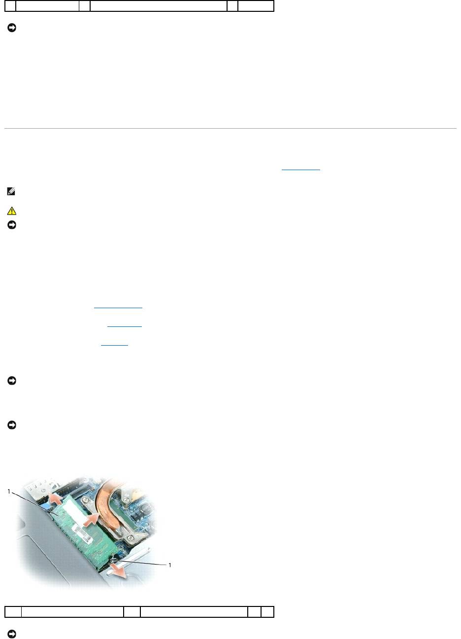
5. If you are replacing a memory module, remove the existing module:
a. Use your fingertips to carefully spread apart the securing clips on each end of the memory module connector until the module pops up.
b. Remove the module from the connector.
4
keyboard cable
5
plasticbaronkeyboardconnector
NOTICE: To avoid scratching the palm rest when replacing the keyboard, hook the tabs along the front edge of the keyboard into the palm rest, and
then secure the keyboard in place.
NOTE: Memory modules purchased from Dell are covered under your computer warranty.
CAUTION: Before you begin any of the procedures in this section, follow the safety instructions in the Product Information Guide.
NOTICE: To prevent damage to the system board, remove the main battery before you service the computer.
NOTICE: If you leave the area, ground yourself again when you return to the computer.
NOTICE: To prevent damage to the memory module connector, do not use tools to spread the memory-module securing clips.
1
memory module
2
securing clips (2)
NOTICE: Insert memory modules at a 45-degree angle to prevent damage to the connector.
6. Ground yourself and install the new memory module:
a. Align the notch in the module edge connector with the tab in the connector slot.
b. Slide the module firmly into the slot at a 45-degree angle, and rotate the module down until it clicks into place. If you do not feel the click, remove
the module and reinstall it.
7. Replace the keyboard (see Keyboard).
8. Replace the hinge cover (see Hinge Cover).
9. Insert the battery into the battery bay, or connect the AC adapter to your computer and an electrical outlet.
10. Turn on the computer.
As the computer boots, it detects the additional memory and automatically updates the system configuration information.
To confirm the amount of memory installed in the computer, click Start, click Help and Support, and then click Computer Information.
To install a memory module in DIMM B:
1. Follow the procedures in Before You Begin.
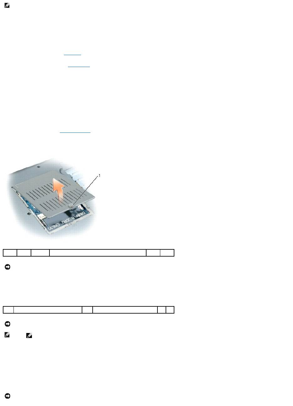
2. Turn the computer upside-down, loosen the captive screw on the memory module cover, and then remove the cover.
3. If you are replacing a memory module, remove the existing module:
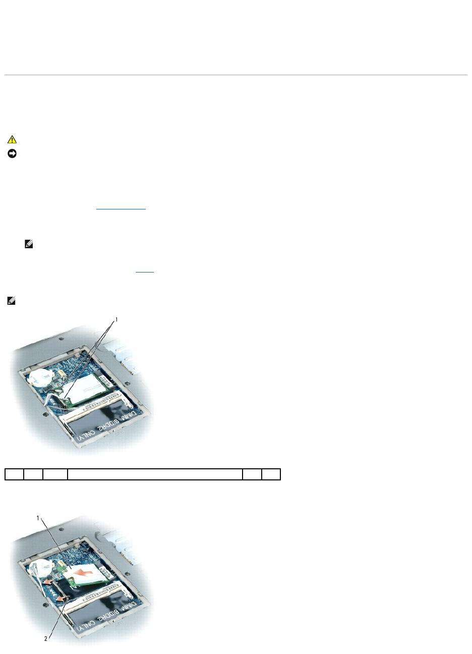
a. Use your fingertips to carefully spread apart the securing clips on each end of the memory module connector until the module pops up.
b. Remove the module from the connector.
4. Ground yourself and install the new memory module:
a. Align the notch in the module edge connector with the tab in the connector slot.
b. Slide the module firmly into the slot at a 45-degree angle, and rotate the module down until it clicks into place. If you do not feel the click, remove
the module and reinstall it.
5. Replace the memory module cover and tighten the screw.
NOTE: If the memory module is not installed properly, the computer may not boot properly. No error message indicates this failure.
1
captive screw
NOTICE: To prevent damage to the memory module connector, do not use tools to spread the memory-module securing clips.
1
securing clips (2)
2
memory module
NOTICE: If you need to install memory modules in two connectors, install a memory module in the connector labeled "DIMMA" before you install a
module in the connector labeled "DIMMB." Insert memory modules at a 45-degree angle to prevent damage to the connector.
NOTE: If the memory module is not installed properly, the computer may not boot properly. No error message indicates this failure.
NOTICE: If the cover is difficult to close, remove the module and reinstall it. Forcing the cover to close may damage your computer.
6. Insert the battery into the battery bay, or connect the AC adapter to your computer and an electrical outlet.
7. Turn on the computer.
As the computer boots, it detects the additional memory and automatically updates the system configuration information.
To confirm the amount of memory installed in the computer, click the Start button, click Help and Support, and then click Computer Information.
Wireless Cards
If you ordered a WLAN card with your computer, the card is already installed.
Wireless Local Area Network (WLAN) Cards
1. Follow the procedures in Before You Begin.
2. Ground yourself by touching one of the metal connectors on the back of the computer.
3. If a card is not already installed, go to step 4. If you are replacing a card, remove the existing card:
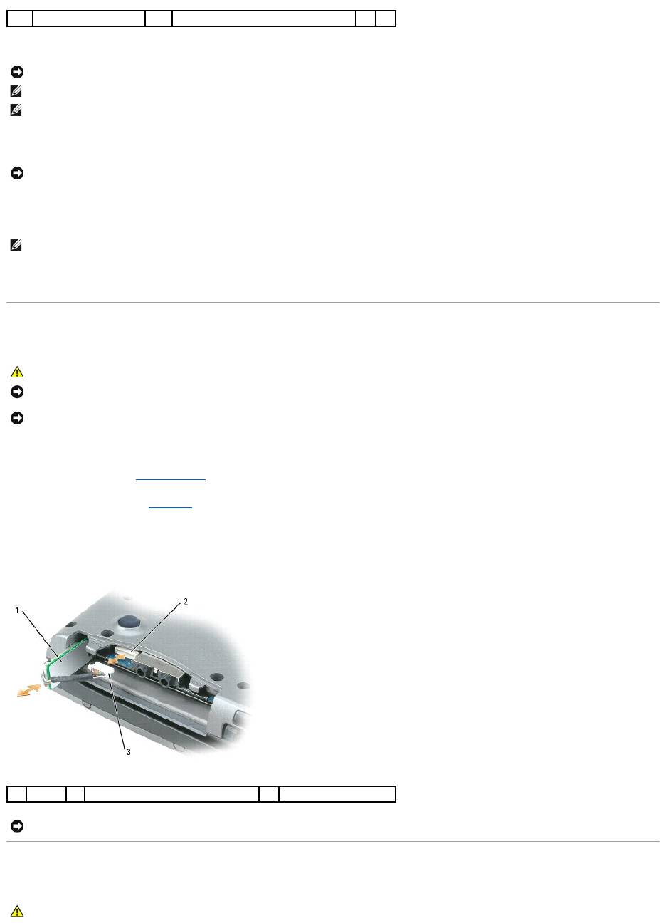
a. Disconnect the antenna cables from the card.
b. Release the card by pushing the metal securing tab away from the card until the card pops up slightly.
CAUTION: Before you begin any of the procedures in this section, follow the safety instructions in the Product Information Guide.
NOTICE: To prevent damage to the system board, remove the main battery before you service the computer.
NOTE: If you leave the area, ground yourself again when you return to the computer.
NOTE: Depending on the type of Mini-Card you have, either two or three of the three antenna cables may be in use.
1
antenna cables (2)
c. Slide the card at a 45-degree angle out of its connector.
4. Install the card:
a. Move any antenna cables out of the way to make space for the WLAN card.
b. Align the card with the connector at a 45-degree angle, and press the card into the connector until it clicks.
5. Connect the antenna cables to the WLAN card, ensuring that you route the cables correctly.
Internal Card With Bluetooth®Wireless Technology
If you ordered an internal card with Bluetooth wireless technology with your computer, it is already installed.
1. Follow the procedures in Before You Begin.
2. Remove the hard drive (see Hard Drive).
3. Pull the card cable connector out of the system board connector.
4. Pull the cable to remove the card from the computer.
Coin-Cell Battery
1
WLAN card
2
metal securing tab
NOTICE: The connectors are keyed to ensure correct insertion. If you feel resistance, check the connectors and realign the card.
NOTE: Do not insert a Mobile Broadband (WWAN) network card into the WLAN card connector.
NOTE: The WLAN card may have two or three antenna connectors, depending on the type of card you ordered.
NOTICE: To avoid damaging the WLAN card, never place cables on top of or under the card.
NOTE: For more specific information about which cable to connect to which connector, see the documentation that came with your WLAN card.
CAUTION: Before performing the following procedures, read the safety instructions in your Product Information Guide.
NOTICE: To avoid electrostatic discharge, ground yourself by using a wrist grounding strap or by periodically touching a connector on the back panel of
the computer.
NOTICE: To prevent damage to the system board, remove the main battery before you service the computer.
1
card
2
system board connector
3
cable connector
NOTICE: Be careful when removing the card to avoid damaging the card, card cable, or surrounding components.
CAUTION: Before performing the following procedures, follow the safety instructions in your Product Information Guide.
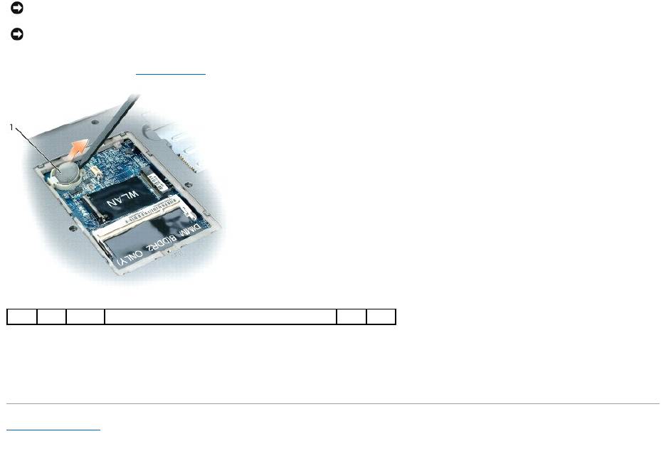
1. Follow the procedures in Before You Begin.
2. Insert a plastic scribe into the guide on the side of the coin-cell battery compartment, and pop the battery out.
When you replace the battery, insert it at a 30-degree angle under the clip with the positive (identified by a plus [+] symbol) side up, and then push it into
place.
Back to Contents Page
NOTICE: To avoid electrostatic discharge, ground yourself by using a wrist grounding strap or by periodically touching a connector on the back panel of
the computer.
NOTICE: To prevent damage to the system board, remove the main battery before you service the computer.
1
coin-cell battery

Back to Contents Page
Dell™QuickSet
Dell™Latitude™D520User'sGuide
Dell™QuickSetprovidesyouwitheasyaccesstoconfigureorviewthefollowingtypesofsettings:
l Network connectivity
l Power management
l Display
l System information
DependingonwhatyouwanttodoinDell™QuickSet,youcanstartitbyeitherclicking, double-clicking, or right-clicking the QuickSet icon, , in the
Microsoft®Windows®taskbar. The taskbar is located in the lower-right corner of your screen.
For more information about QuickSet, right-click the QuickSet icon and select Help.
Back to Contents Page
NOTE: This feature may not be available on your computer.
Back to Contents Page
Securing Your Computer
Dell™Latitude™D520User'sGuide
Security Cable Lock
Passwords
Computer Tracking Software
If Your Computer Is Lost or Stolen
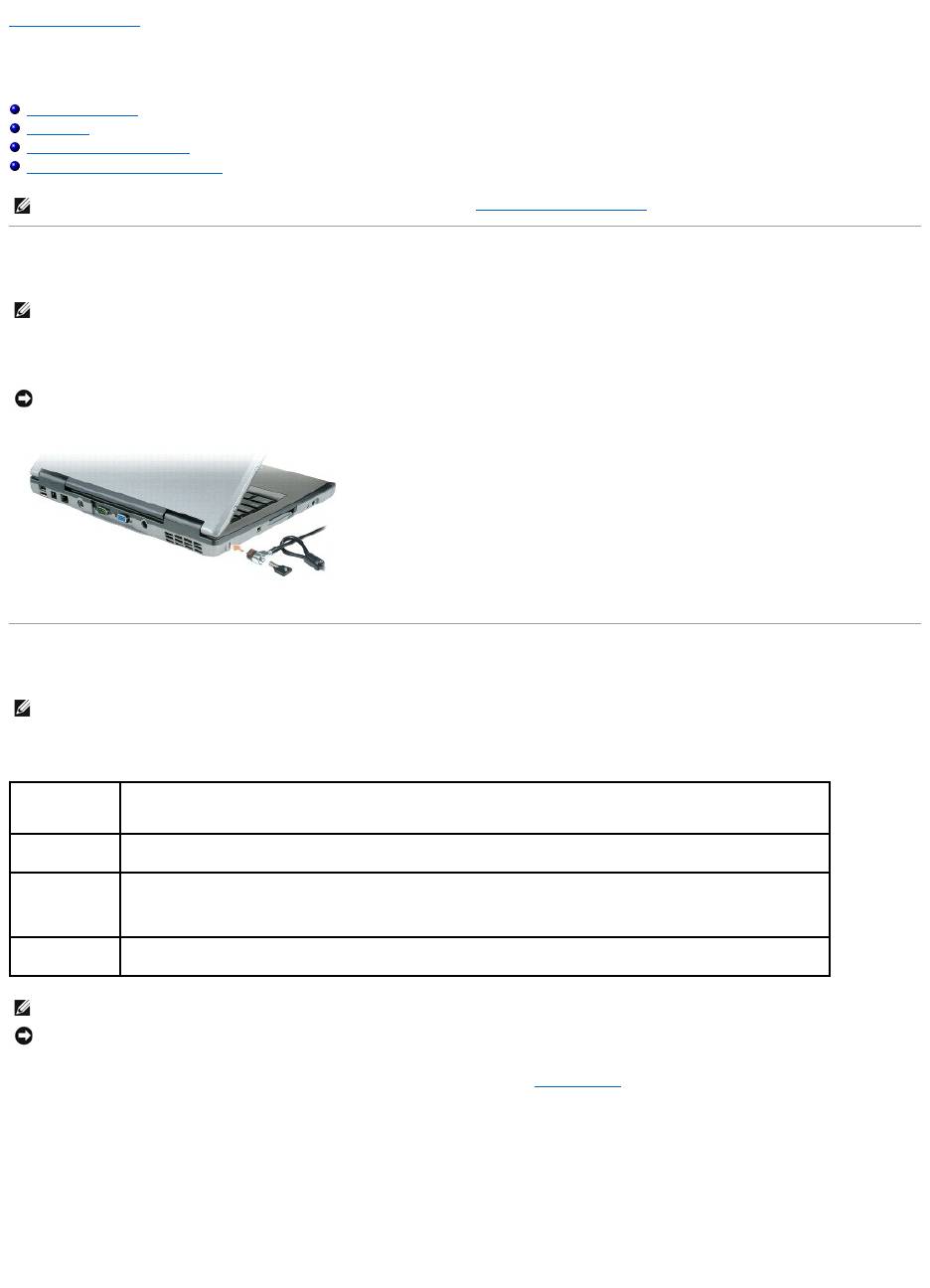
Security Cable Lock
Asecuritycablelockisacommerciallyavailableantitheftdevice.Tousethelock,attachittothesecuritycableslotonyourDell™computer.Formore
information, see the instructions included with the device.
Passwords
A primary password, an administrator password, and a hard drive password all prevent unauthorized access to your computer in different ways. The following
table identifies types and features of passwords available on your computer.
If you forget any of your passwords, contact your system administrator or contact Dell (see Contacting Dell). For your protection, Dell support staff will ask you
for proof of your identity to ensure that only an authorized person can use the computer.
Using a Primary/System Password
The primary (system) password allows you to protect the computer from unauthorized access.
Access User Accounts from the Control Panel to create user accounts and add or change passwords. After assigning a primary password, you must enter it
each time you turn on your computer.
If you do not enter a password within 2 minutes, the computer returns to its previous operating state.
NOTE: For information on how to secure your computer while traveling, see Traveling With Your Computer.
NOTE: Your computer does not ship with a security cable lock.
NOTICE: Before you buy an antitheft device, ensure that it will work with the security cable slot on your computer.
NOTE: Passwords are disabled when you receive your computer.
Type of Password
Features
Primary/System
l Protects the computer from unauthorized access
Administrator
l Gives system administrators or service technicians access to computers for repair or reconfiguration
l Allows you to restrict access to system setup in the same way a primary password restricts access to the computer
l Can be used instead of the primary password
Hard drive
l Helps protect the data on your hard drive or external hard drive (if one is being used) from unauthorized access
NOTE: Some hard drives do not support hard drive passwords.
NOTICE: Passwords provide a high level of security for data in your computer or hard drive. However, they are not foolproof. If you require more
security, obtain and use additional forms of protection, such as smart cards, data encryption programs, or PC Cards with encryption features.

If you have assigned an administrator password, you can use it instead of the primary password. The computer does not specifically prompt you for the
administrator password.
Using an Administrator Password
The administrator password is designed to give system administrators or service technicians access to computers for repair or reconfiguration. The
administrators or technicians can assign identical administrator passwords to groups of computers, allowing you to assign a unique primary password.
To set or change administrator passwords, access User Accounts from the Control Panel.
When you set an administrator password, the Configure Setup option becomes available in the system setup program. The Configure Setup option allows
you to restrict access to system setup in the same way that a primary password restricts access to the computer.
The administrator password can be used instead of the primary password. Whenever you are prompted to enter the primary password, you can enter the
administrator password.
If you forget the primary password and do not have an administrator password assigned, or if you have both a primary and an administrator password
assigned but forget them both, contact your system administrator or contact Dell (see Contacting Dell).
Using a Hard Drive Password
The hard drive password helps protect the data on your hard drive from unauthorized access. You can also assign a password for an external hard drive (if
one is being used) that can be the same as or different from the password for the primary hard drive.
After assigning a hard drive password, you must enter it each time you turn on the computer and each time you restore the computer to normal operation
from standby mode.
If the hard drive password is enabled, you must enter it each time you turn on the computer: A message appears asking for the hard drive password.
To continue, enter your password (with no more than eight characters) and press <Enter>.
If you do not enter a password within 2 minutes, the computer returns to its previous operating state.
If you enter the wrong password, a message tells you that the password is invalid. Press <Enter> to try again.
If you do not enter the correct password in three attempts, the computer tries to start from another bootable device if the Boot First Device option in the
system setup program is set to allow start-up from another device. If the Boot First Device option is not set to allow the computer to start from another
device, the computer returns to the operating state it was in when you turned it on.
If the hard drive password, the external hard-drive password, and the primary password are the same, the computer prompts you only for the primary
password. If the hard drive password is different from the primary password, the computer prompts you for both. Two different passwords provide greater
security.
Computer Tracking Software
Computer tracking software may enable you to locate your computer if it is lost or stolen. The software is optional and may be purchased when you order your
Dell™computer,oryoucancontactyourDellsalesrepresentativeforinformationaboutthissecurityfeature.
If Your Computer Is Lost or Stolen
l Call a law enforcement agency to report the lost or stolen computer. Include the Service Tag in your description of the computer. Ask that a case
number be assigned and write down the number, along with the name, address, and phone number of the law enforcement agency. If possible, obtain
the name of the investigating officer.
l If the computer belongs to a company, notify the security office of the company.
l Contact Dell customer service to report the missing computer. Provide the computer Service Tag, the case number, and the name, address, and phone
number of the law enforcement agency to which you reported the missing computer. If possible, give the name of the investigating officer.
NOTICE: If you disable the administrator password, the primary password is also disabled.
NOTICE: If you disable the administrator password, the primary password is also disabled.
NOTE: The administrator password provides access to the computer, but it does not provide access to the hard drive when a hard drive password is
assigned.
NOTE: The administrator password provides access to the computer, but it does not provide access to the hard drive when a hard drive password is
assigned.
NOTE: Computer tracking software may not be available in certain countries.
NOTE: If you have computer tracking software and your computer is lost or stolen, you must contact the company that provides the tracking service to
report the missing computer.
NOTE: If you know where the computer was lost or stolen, call a law enforcement agency in that area. If you do not know, call a law enforcement
agency where you live.

The Dell customer service representative will log your report under the computer Service Tag and record the computer as missing or stolen. If someone calls
Dell for technical assistance and gives your Service Tag, the computer is identified automatically as missing or stolen. The representative will attempt to get
the phone number and address of the caller. Dell will then contact the law enforcement agency to which you reported of the missing computer.
Back to Contents Page

Back to Contents Page
System Setup Program
Dell™Latitude™D520User'sGuide
Overview
Viewing the System Setup Screens
System Setup Screens
Commonly Used Settings
Overview
You can use the system setup program as follows to:
l Set or change user-selectable features—for example, your computer password
l Verify information about the computer's current configuration, such as the amount of system memory
After you set up the computer, run the system setup program to familiarize yourself with your system configuration information and optional settings. You may
want to write down the information for future reference.
The system setup screens display the current setup information and settings for your computer, such as:
l System configuration
l Boot order
l Boot (start-up) configuration and docking-device configuration settings
l Basic device-configuration settings
l System security and hard-drive password settings
Viewing the System Setup Screens
1. Turn on (or restart) your computer.
2. WhentheDELL™logoappears,press<F2>immediately.IfyouwaittoolongandtheWindowslogoappears,continuetowaituntilyouseethe
Windows desktop. Then shut down your computer and try again.
System Setup Screens
In the system setup program, primary categories of settings are listed on the left. To view the types of settings in a category, highlight the category and press
<Enter>. When you highlight a setting type, the right side of the screen displays the value for that setting type. You can change settings that appear as white
type on the screen. Values that you cannot change (because they are determined by the computer) appear less bright.
System-setup key functions are listed across the bottom of the screen.
Commonly Used Settings
Certain settings require that you reboot the computer for new settings to take effect.
Changing the Boot Sequence
The boot sequence tells the computer where to look to find the software needed to start the operating system. You can control the boot sequence and
enable/disable devices using the Boot Sequence page, which is located in the System category.
NOTE: Your operating system may automatically configure most of the options available in the system setup program, thus overriding options that you
set through the system setup program. (An exception is the External Hot Key option, which you can disable or enable only through the system setup
program.) For more information on configuring features for your operating system, access the Help and Support Center (see Windows Help and Support
Center).
NOTICE: Unless you are an expert computer user or are directed to do so by Dell technical support, do not change the system setup settings. Certain
changes might make your computer work incorrectly.
NOTE: For information about a specific item on a system setup screen, highlight the item and see the Help area on the screen.

The Boot Sequence page displays a general list of the bootable devices that may be installed in your computer, including but not limited to the following:
l Diskette Drive
l Modular bay HDD
l Internal HDD
l CD/DVD/CD-RW drive
During the boot routine, the computer starts at the top of the list and scans each enabled device for the operating system start-up files. When the computer
finds the files, it stops searching and starts the operating system.
To control the boot devices, select (highlight) a device by pressing the down-arrow or up-arrow key, and then enable or disable the device or change its order
in the list.
l To enable or disable a device, highlight the item and press the space bar. Enabled items appear as white and display a small triangle to the left;
disabled items appear blue or dimmed without a triangle.
l To reorder a device in the list, highlight the device and then press <u> or <d> (not case-sensitive) to move the highlighted device up or down.
Boot sequence changes take effect as soon as you save the changes and exit the system setup program.
Performing a One-Time Boot
You can set a one-time-only boot sequence without entering the system setup program. (You can also use this procedure to boot the Dell Diagnostics on the
diagnostics utility partition on your hard drive.)
1. Shut down the computer through the Start menu.
2. If the computer is connected to a docking device (docked), undock it. See the documentation that came with your docking device for instructions.
3. Connect the computer to an electrical outlet.
4. Turn on the computer. When the DELL logo appears, press <F12> immediately. If you wait too long and the Windows logo appears, continue to wait
until you see the Windows desktop. Then shut down your computer and try again.
5. When the boot device list appears, highlight the device from which you want to boot and press <Enter>.
The computer boots to the selected device.
The next time you reboot the computer, the previous boot order is restored.
Changing COM Ports
Serial Port, which is located in the Onboard Devices category, allows you to map the serial port COM address or disable the serial port and its address, which
frees computer resources for another device to use.
Enabling the Infrared Sensor
1. Locate Fast IR under Onboard Devices.
2. Press <Enter>.
3. Use the arrow keys to select the infrared COM port setting.
4. Press <Enter>.
5. Follow the instructions on the screen.
After you enable the infrared sensor, you can use it to establish a link to an infrared device. To set up and use an infrared device, see the infrared device
documentation and the Windows Help and Support Center. To access the Windows Help and Support Center, see Windows Help and Support Center.
Back to Contents Page
NOTE: To change the boot sequence on a one-time-only basis, see Performing a One-Time Boot.
NOTE: Ensure that the COM port that you select is different from the COM port assigned to the serial connector.


Back to Contents Page
Reinstalling Software
Dell™Latitude™D520User'sGuide
Drivers
Software and Hardware Incompatibilities
Restoring Your Operating System
Drivers
What Is a Driver?
A driver is a program that controls a device such as a printer, mouse, or keyboard. All devices require a driver program.
A driver acts like a translator between the device and any other programs that use the device. Each device has its own set of specialized commands that only
its driver recognizes.
Dell ships your computer to you with required drivers already installed—no further installation or configuration is needed.
Many drivers, such as the keyboard driver, come with your Microsoft
®
Windows
®
operating system. You may need to install drivers if you:
l Upgrade your operating system.
l Reinstall your operating system.
l Connect or install a new device.
Identifying Drivers
If you experience a problem with any device, identify whether the driver is the source of your problem and, if necessary, update the driver.
1. Click Start® Control Panel® System.
2. Click Hardware® Device Manager.
3. Scroll down the list to see if any device has an exclamation point (a yellow circle with a [!]) on the device icon.
If an exclamation point is next to the device name, you may need to reinstall the driver or install a new driver (see Reinstalling Drivers and Utilities).
Reinstalling Drivers and Utilities
Using Windows XP Device Driver Rollback
If a problem occurs on your computer after you install or update a driver, use Windows XP Device Driver Rollback to replace the driver with the previously
installed version.
1. Click Start® Control Panel® System.
2. Click Hardware® Device Manager.
3. Right-click the device for which the new driver was installed and click Properties.
4. Click Drivers® Roll Back Driver.
If Device Driver Rollback does not resolve the problem, then use System Restore to return your computer to the operating state that existed before you
installed the new driver (see Using Microsoft Windows XP System Restore).
NOTICE: The optional Drivers and Utilities CD may contain drivers for operating systems that are not on your computer. Ensure that you are installing
software appropriate for your operating system.
NOTICE: The Dell Support website at support.dell.com and your Drivers and UtilitiesCDprovideapproveddriversforDell™computers.Ifyouinstall
drivers obtained from other sources, your computer might not work correctly.

Using the Drivers and Utilities CD
If using Device Driver Rollback or System Restore does not resolve the problem, then reinstall the driver from the Drivers and Utilities CD (also known as the
ResourceCD).
1. Save and close any open files, and exit any open programs.
2. Insert the Drivers and Utilities CD.
In most cases, the CD starts running automatically. If it does not, start Windows Explorer, click your CD drive directory to display the CD contents, and
then double-click the autorcd.exe file. The first time that you run the CD, it might prompt you to install setup files. Click OK, and follow the instructions
on the screen to continue.
3. From the Language drop-down menu in the toolbar, select your preferred language for the driver or utility (if available). A welcome screen appears.
4. Click Next.
The CD automatically scans your hardware to detect drivers and utilities used by your computer.
5. After the CD completes the hardware scan, you can also detect other drivers and utilities. Under Search Criteria, select the appropriate categories from
the System Model, Operating System, and Topic drop-down menus.
A link or links appear(s) for the specific drivers and utilities used by your computer.
6. Click the link of a specific driver or utility to display information about the driver or utility that you want to install.
7. Click Install (if present) to begin installing the driver or utility. At the welcome screen, follow the screen prompts to complete the installation.
If Install is not present, automatic installation is not an option. For installation instructions, either see the appropriate instructions in the following
subsections, or click Extract, follow the extracting instructions, and then read the readme file.
If instructed to navigate to the driver files, click the CD directory on the driver information window to display the files associated with that driver.
Manually Reinstalling Drivers
1. After extracting the driver files to your hard drive as described in the previous section, right-click My Computer on the Windows desktop® Properties®
Hardware® Device Manager.
2. Double-click the type of device for which you are installing the driver (for example, Modems or Infrared devices).
3. Double-click the name of the device for which you are installing the driver.
4. Click Driver® Update Driver.
5. Click Install from a list or specific location (Advanced)® Next.
6. Click Browse and browse to the location to which you previously copied the driver files.
7. When the name of the appropriate driver appears, click Next® Finish and restart your computer.
Software and Hardware Incompatibilities
If a device is either not detected during the operating system setup or is detected but incorrectly configured, you can use the Hardware Troubleshooter to
resolve the incompatibility.
1. Click Start® Help and Support.
2. Type hardware troubleshooter in the Search field and click the arrow to start the search.
3. Click Hardware Troubleshooter® I need to resolve a hardware conflict on my computer® Next.
NOTE: The Drivers and Utilities CD may be optional and may not ship with your computer.
NOTE: If you are reinstalling an infrared sensor driver, you must first enable the infrared sensor in the system setup program (see Enabling the Infrared
Sensor) before continuing with the driver installation.

Restoring Your Operating System
You can restore your operating system in the following ways:
l Microsoft
®
Windows
®
XP System Restore returns your computer to an earlier operating state without affecting data files. Use System Restore as the
first solution for restoring your operating system and preserving data files.
l If you received an Operating System CD with your computer, you can use it to restore your operating system. However, using the Operating System CD
also deletes all data on the hard drive. Use the CD only if System Restore did not resolve your operating system problem.
Using Microsoft Windows XP System Restore
The Microsoft Windows XP operating system provides System Restore to allow you to return your computer to an earlier operating state (without affecting
data files) if changes to the hardware, software, or other system settings have left the computer in an undesirable operating state. See the Windows Help
and Support Center for information on using System Restore. To access the Windows Help and Support Center, see Windows Help and Support Center.
Creating a Restore Point
1. Click Start® Help and Support.
2. Click the task for System Restore.
3. Follow the instructions on the screen.
Restoring the Computer to an Earlier Operating State
If problems occur after you install a device driver, use Device Driver Rollback (see Using Windows XP Device Driver Rollback) to resolve the problem. If that is
unsuccessful, then use System Restore.
1. Click Start® All Programs® Accessories® System Tools® System Restore.
2. Ensure that Restore my computer to an earlier time is selected and click Next.
3. Click a calendar date to which you want to restore your computer.
The Select a Restore Point screen provides a calendar that allows you to see and select restore points. All calendar dates with available restore points
appear in boldface type.
4. Select a restore point and click Next.
If a calendar date has only one restore point, then that restore point is automatically selected. If two or more restore points are available, click the
restore point that you prefer.
5. Click Next.
The Restoration Complete screen appears after System Restore finishes collecting data and then the computer restarts.
6. After the computer restarts, click OK.
To change the restore point, you can either repeat the steps using a different restore point, or you can undo the restoration.
Undoing the Last System Restore
1. Click Start® All Programs® Accessories® System Tools® System Restore.
2. Click Undo my last restoration® Next.
NOTICE: Make regular backups of your data files. System Restore does not monitor your data files or recover them.
NOTE: TheproceduresinthisdocumentwerewrittenfortheWindowsdefaultview,sotheymaynotapplyifyousetyourDell™computertothe
Windows Classic view.
NOTICE: Before you restore the computer to an earlier operating state, save and close any open files and exit any open programs. Do not alter, open,
or delete any files or programs until the system restoration is complete.
NOTICE: Before you undo the last system restore, save and close all open files and exit any open programs. Do not alter, open, or delete any files or
programs until the system restoration is complete.

Enabling System Restore
If you reinstall Windows XP with less than 200 MB of free hard-disk space available, System Restore is automatically disabled. To see if System Restore is
enabled:
1. Click Start® Control Panel® Performance and Maintenance® System® System Restore.
2. Ensure that Turn off System Restore is unchecked.
Using the Operating System CD
Before You Begin
If you are considering reinstalling the Windows XP operating system to correct a problem with a newly installed driver, first try using Windows XP Device Driver
Rollback (see Using Windows XP Device Driver Rollback). If Device Driver Rollback does not resolve the problem, then use System Restore to return your
operating system to the operating state it was in before you installed the new device driver (see Using Microsoft Windows XP System Restore).
To reinstall Windows XP, you need the following items:
l Dell™Operating System CD
l Dell Drivers and Utilities CD
Reinstalling Windows XP
The reinstallation process can take 1 to 2 hours to complete. After you reinstall the operating system, you must also reinstall the device drivers, virus
protection program, and other software.
1. Save and close any open files and exit any open programs.
2. Insert the Operating System CD. Click Exit if the Install Windows XP message appears and restart the computer.
3. Press<F12>immediatelyaftertheDELL™logoappears.
If the operating system logo appears, wait until you see the Windows desktop, and then shut down the computer and try again.
4. Follow the instructions on the screen to complete the installation.
Back to Contents Page
NOTE: The Drivers and Utilities CD contains drivers that were installed during assembly of the computer. Use the Drivers and Utilities CD to load any
required drivers. Depending on the region from where you ordered your computer, or whether you requested the CDs, the Drivers and Utilities CD and
Operating System CD may not ship with your system.
NOTICE: The optional Operating System CD provides options for reinstalling Windows XP. The options can overwrite files and possibly affect programs
installed on your hard drive. Therefore, do not reinstall Windows XP unless a Dell technical support representative instructs you to do so.

Back to Contents Page
Specifications
Dell™Latitude™D520User'sGuide
Processor
Processor type
Intel®Core™2Duoprocessor,IntelCoreDuo
processor, Intel Core Solo processor, or Intel
Celeron®M processor
L1 cache
32 KB (internal)
L2 cache
up to 4 MB (on die), depending on your Intel Core
processor, and 1 MB for Celeron M processor
External bus frequency
533 or 667 MHz
SystemInformation
System chipset
Intel 945GM or Intel 940GML
Data bus width
64 bits
DRAM bus width
64 bits
Processor address bus width
36 bits
PCCard
CardBus controller
O2Micro OZ711EZ1 (PC Cards and 34-mm
ExpressCards)
(support for USB ExpressCards through adapter in
CardBus slot)
PC Card connector
one (supports one Type I or Type II card and one 34-
mm ExpressCard with adapter)
NOTE: You must use an adapter with the 34-mm
ExpressCard before you insert the card into the PC
Card connector.
Cards supported
3.3 V and 5 V PC Cards
1.5 V ExpressCards (with adapter)
PC Card connector size
68 pins
Data width (maximum)
PCMCIA 16 bits
CardBus 32 bits
Memory
Memory module connector
two user-accessible SODIMM sockets
Memory module capacities
256 MB, 512 MB, 1 GB, and 2 GB
Memory type
533/667-MHz DDRII SDRAM
Minimum memory
256 MB
Maximum memory
up to 4 GB for 945GM chipset, and up to 2 GB for
940GML chipset
PortsandConnectors
Serial
9-pin connector; 16550C-compatible,
16-byte buffer connector
Video
15-hole connector
Audio
microphone miniconnector, stereo
headphones/speakers miniconnector
S-video TV-out
7-pin mini-DIN connector (optional adapter cable(s)
with S-video and composite video connectors)
USB
four 4-pin USB 2.0-compliant connectors
Infrared sensor
sensor compatible with IrDA Standard 1.1 (Fast IR)
and IrDA Standard 1.0 (Slow IR)
Modem
RJ-11 support

IEEE 1394a
4-pin serial connector
Mini-Card
one Type IIIA Mini-Card slot
Network adapter
RJ-45 port
D-Port
standard docking connector for D/Port advanced port
replicator
Communications
Modem:
Type
v.92 56K MDC
Controller
softmodem
Interface
Intel High-Definition Audio
Network adapter
10/100 Ethernet LAN on system board
Wireless
internal PCI-e Mini-Card WLAN support; Bluetooth®
wireless technology support;
WWAN support via ExpressCard with adapter in PC
Card/ExpressCard slot
Video
Video type
Intel GMA 950
Data bus
PCI Express
Controller/Memory
1 MB with Dynamic Virtual Memory Technology
(DVMT), up to 64 MB (with 256 MB of system
memory), or 128 MB (with 512 MB or more of system
memory)
LCD interface
LVDS
TV support
NTSC or PAL in S-video and composite modes
(throughDell™D/Portadvancedportreplicatoronly)
Audio
Audio type
High Definition Audio (HDA)
Audio controller
SigmaTel STAC9200
Stereo conversion
20-bit (stereo digital-to-analog),
18-bit (stereo analog-to-digital)
Interfaces:
Internal
Azalia/AC'97
External
microphone mini-connector, stereo
headphones/speakers mini-connector
Speaker
two 8-ohm speakers
Internal speaker amplifier
1-W channel into 8 ohms
Volume controls
volume control buttons or program menus
Display
Type (active-matrix TFT)
14.1-inch and 15.0-inch XGA
15.0-inch SXGA+
Dimensions (14-inch display):
Height
214.3 mm (8.4 inches)
Width
285.7 mm (11.3 inches)
Diagonal
357.1 mm (14.1 inches)
Dimensions (15.1-inch display):
Height
228.1 mm (8.9 inches)
Width
304.1 mm (12.0 inches)
Diagonal
381.0 mm (15 inches)
Operating angle
0°(closed)to180°
Viewing angles:
XGA horizontal
+/– 40/40°
XGA vertical
+/– 10/30°
SXGA+ horizontal
+/– 65/65°
SXGA+ vertical
+/– 50/50°
Pixel pitch:

XGA
0.297 mm (0.012 inch)
SXGA+
0.217 mm (0.008 inch)
Power consumption (panel with backlight) (typical):
XGA
5.0 W (max.)
SXGA+
4.8 W (max.)
Controls
brightness can be controlled through keyboard
shortcuts
Keyboard
Number of keys
87 (U.S. and Canada); 87 (China); 89 (Brazil); 88
(Europe); 91 (Japan)
Key travel
2.5 mm ± 0.3 mm (0.11 inch ± 0.016 inch)
Key spacing
19.05 mm ± 0.3 mm (0.75 inch ± 0.012 inch)
Layout
QWERTY/AZERTY/Kanji
TouchPad
X/Ypositionresolution(graphicstablemode)
240 cpi
Size:
Width
64.88 mm (2.55-inch) sensor-active area
Height
48.88-mm (1.92-inch) rectangle
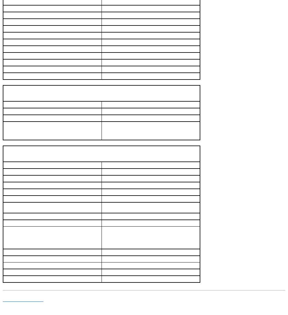
Battery
Type
6-cell "smart" lithium ion (56 WHr) (standard)
6-cell "smart" lithium ion (48 WHr) (optional in media
bay)
4-cell "smart" lithium ion (32 WHr) (optional)
Dimensions:
Depth
77.5 mm (3.05 inches)
Height
19.5 mm (0.76 inch)
Width
123.4 mm (4.86 inches)
Weight
0.32kg(0.70lb)(6cell)0.23kg(0.52lb)(4cell)
Voltage
14.8 VDC (4 cell)
11.1 VDC (6 cell)
Charge time (approximate):
Computer off
approximately 1 hour for 80 percent charge
Operating time
varies depending on operating conditions and can be
significantly reduced under certain power-intensive
conditions.
See Battery Performance for more information.
Life span (approximate)
300 discharge/charge cycles
Temperature range:
Operating
0° to40°C(32°to104°F)
Storage
–40° to60°C(–40°to140°F)
ACAdapter
Input voltage
100–240 VAC
Input current (maximum)
1.5 A
Input frequency
50–60 Hz
Output current
3.34 A (65-W AC adapter)
4.62 A (90-W AC adapter)
Output power
65 W
90 W
Rated output voltage
19.5 VDC
Dimensions and weight (65-W AC adapter):
Back to Contents Page
Height
28.3 mm (1.11 inches)
Width
57.8 mm (2.28 inches)
Depth
137.2 mm (5.40 inches)
Weight (with cables)
0.36 kg (0.79 lb)
Dimensions and weight (90-W AC adapter):
Height
34.2 mm (1.35 inches)
Width
60.9 mm (2.39 inches)
Depth
153.42 mm (6.04 inches)
Weight (with cables)
0.46 kg (1.01 lb)
Temperature range:
Operating
0°to40°C(32°to104°F)
Storage
–40°to60°C(–40°to140°F)
Physical
Height
35.8 mm (1.4 inches)
Width
338.3 mm (13.3 inches)
Depth
273.0 mm (10.8 inches)
Weight
approximately 5.24 lb (2.38 kg), with a 14.1-inch XGA
display,DellTravelLite™module,and4-cell battery;
weight varies, depending on configuration and
manufacturing variability
Environmental
Temperature range:
Operating
0° to35°C(32°to95°F)
Storage
–40°to60°C(–40°to140°F)
Relative humidity (maximum):
Operating
10% to 90% (noncondensing)
Storage
5% to 95% (noncondensing)
Maximum vibration (using a random-vibration
spectrum that simulates user environment):
Operating
0.66 GRMS
Storage
1.30 GRMS
Maximum shock (measured with hard drive in
operating status and a 2-ms half-sine pulse for
operating; also measured with hard drive in head-
parked position and a 2-ms half-sine pulse for
storage):
Operating
142 G, 70 inches/sec
Storage
163 G, 80 inches/sec
Altitude (maximum):
Operating
–15.2 to 3048 m (–50 to 10,000 ft)
Storage
–15.2 to 10,668 m (–50 to 35,000 ft)
