Asus A8V-X: 1. Motherboard-Layout
1. Motherboard-Layout: Asus A8V-X
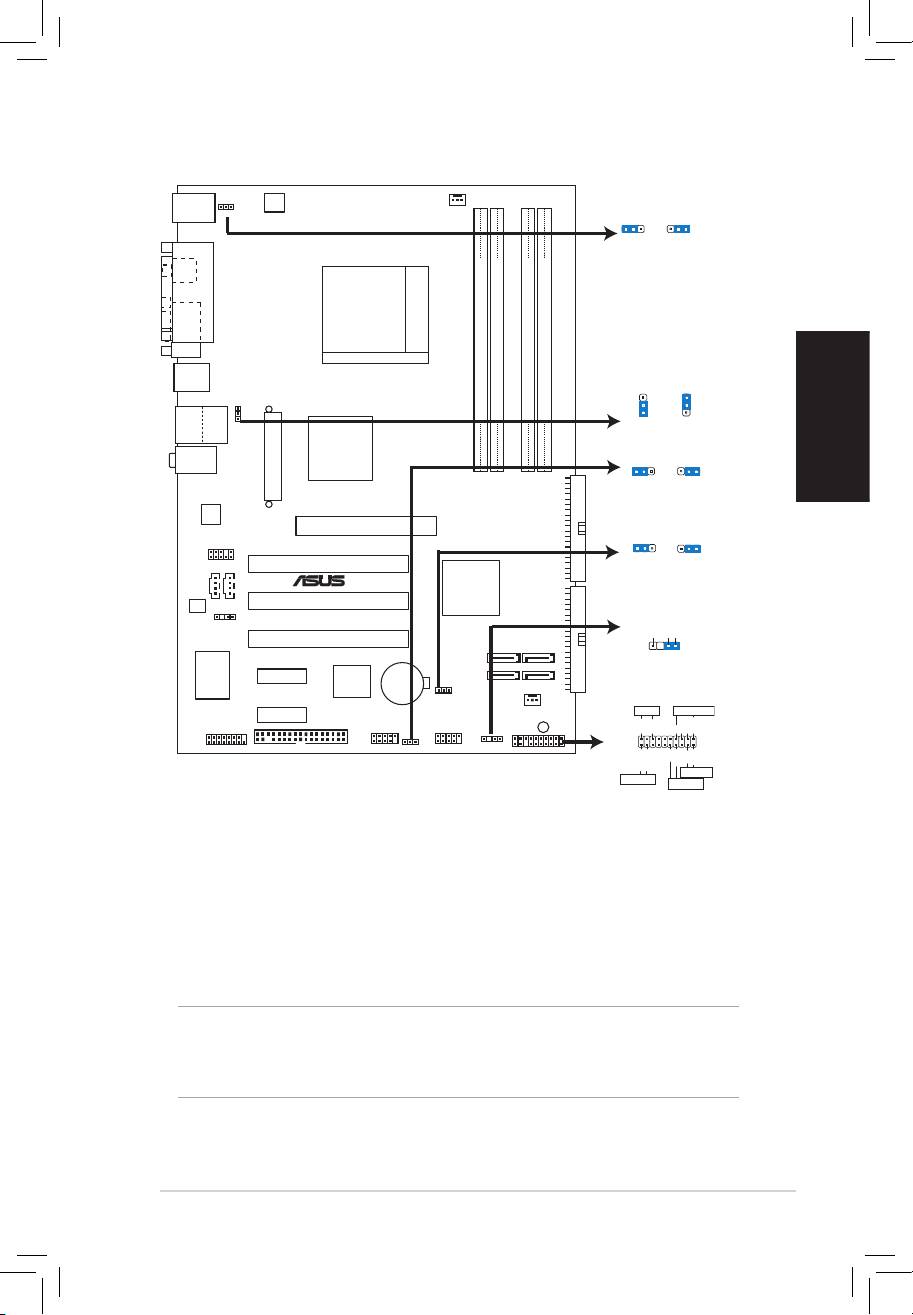
1. Motherboard-Layout
Deutsch
2. Installieren der CPU
Folgen Sie bitte den nachstehenden Schritten, um eine CPU zu installieren.
1. Suchen Sie auf dem Motherboard den 939-pol. ZIF-Sockel.
2. Heben Sie den Sockelhebel bis zu einem Winkel von 90 Grad hoch.
WARNUNG!
Die CPU passt nur in einer Richtung in den Sockel. Stecken Sie die CPU nicht
gewaltsam hinein, um verbogene Kontaktstifte und Schäden an der CPU zu
vermeiden!
ASUS A8V-X
5
PS/2KBMS
CPU_FAN
T: M
ouse
KBPWR
B: Keyboard
KBPWR
ATX12V
21
2
3
+5V
+5VSB
(Default)
SPDIF_O
PARALLEL PORT
Socket 939
COM1
F_USB12
A8V-X
USBPW1234
USBPW1234
3
2
2
Bottom:
DDR DIMM_A1 (64 bit,184-pin module)
DDR DIMM_A2 (64 bit,184-pin module)
DDR DIMM_B1 (64 bit,184-pin module)
DDR DIMM_B2 (64 bit,184-pin module)
1
Top:
USB3
+5V
+5VSB
RJ-45
USB4
(Default)
VIA
Top:Line In
K8T800 PRO
USBPW5678
Center:Line Out
Below:Mic In
21
2
3
ATXPWR
+5V
+5VSB
(Default)
PRI_IDE
RTL8201CL
AGP
CLRTC
1 2
2 3
AAFP
Normal Clear CMOS
PCI1
(Default)
®
AUX CD
VIA
VT8251
PCI2
AD1986A
SEC_IDE
SPDIF_OUT
+5VSB_MB
Chassis Signal
GND
PCI3
SATA4
SATA2
(Default)
ITE
PCIEX1_1
4Mbit
CR2032 3V
CHASSIS
BIOS
Lithium Cell
IT8712F-A
CMOS Powe
r
SATA3
SATA1
CLRT
C
CHA_F
AN
PCIEX1_2
PLED
SPEAKER
FLOPPY
GAME
SB_PWR
PLED+
PLED-
+5V
Ground
Ground
Speaker
USBPW5678
PANEL
USB56
USB78
CHASISS
PANEL
PWR
Ground
Reset
Ground
IDE_LED+
IDE_LED-
RESET
IDE_LED
PWRSW
* Requires an ATX power supply.
Оглавление
- 1. Layout de la Carte Mère 2. Installation du Processeur
- 3. Mémoire Système
- 1. Motherboard-Layout
- 3. Arbeitsspeicher
- 5. Software Support CD-Informationen
- 1. Diagramma disposizione scheda madre 2. Installazione della CPU
- 3. Memoria di sistema
- 4. Informazioni sul BIOS
- 1. Distribución de la placa base
- 3. Memoria de sistema
- 5. Información sobre el CD de soporte de Software
- 1. Схема системной платы 2. Установка процессора
- 3. Системная память
- 4. Информация BIOS
- 1. Disposição da Motherboard 2. Instalação da CPU
- 3. Memória do sistema
- 4. Informação da BIOS
- 1. Plan płyty głównej 2. Instalacja CPU
- 3. Pamięć systemowa.
- 4. Informacje BIOS
- 1. Rozvrženízákladnídesky
- 3. Systémovápamět’
- 4. InformaceoBIOSu
- 1. Az alaplap felépítése 2. A CPU beszerelése
- 3. Rendszermemória
- 4. BIOS információk
- 1. Схеманадъннатаплатка
- 3. Системнапамет
- 4. BIOSинформация
- 1. Schema plăcii de bază
- 3. Memoria sistemului
- 4. Informaţii despre BIOS
- 1. Izgled matične ploče 2. Instalacija procesora
- 3. Sistemska memorija
- 4. BIOS
