Asus A7S8X-MX: Chapter 5
Chapter 5: Asus A7S8X-MX
Chapter 5
Software support

ASUS A7S333 motherboard

5.1 Install an operating system
This motherboard supports Windows 98/ME/NT/2000/XP and OS/2 operating
system (OS). Always install the latest OS version and corresponding updates
so you can maximize the features of your hardware.
5.1.1 Windows first time installation
When you start Windows for the first time after installing the motherboard,
Windows detects all Plug-n-Play devices devices. Follow the Add New
Hardware wizard to install the necessary device drivers. When prompted to
restart, select No. Refer to the following sections in this chapter to install the
software and drivers contained in the support CD.
NOTE! Because motherboard settings and hardware options vary, use
the setup procedures presented in this chapter for general reference only.
Refer to your OS documentation for more information.
5.2 Support CD information
The support CD that came with the motherboard contains useful software
and several utility drivers that enhance the motherboard features.
NOTE! The contents of the support CD are subject to change at any
time without notice. Visit the ASUS website for updates.
5.2.1 Running the support CD
To begin using the support CD, simply insert the CD into your CD-ROM
drive. The CD automatically displays the welcome screen and the installation
menus if Autorun is enabled in your computer.
ASUS A7S333 motherboard user guide
77
5.3 A7S333 Motherboard Support CD
NOTE: The support CD contents are subject to change without notice.
To begin using your support CD disc, just insert it into your CD-ROM drive
and the support CD installation menu should appear. If the menu does not
appear, double-click or run D:\ASSETUP.EXE.
5.3.1 Installation Procedure
Click on the name of the driver or program group to begin installation. Follow
the instructions that appear on the setup screens. All drivers and programs
install automatically. Refer to 6. Software Reference for operating instructions.
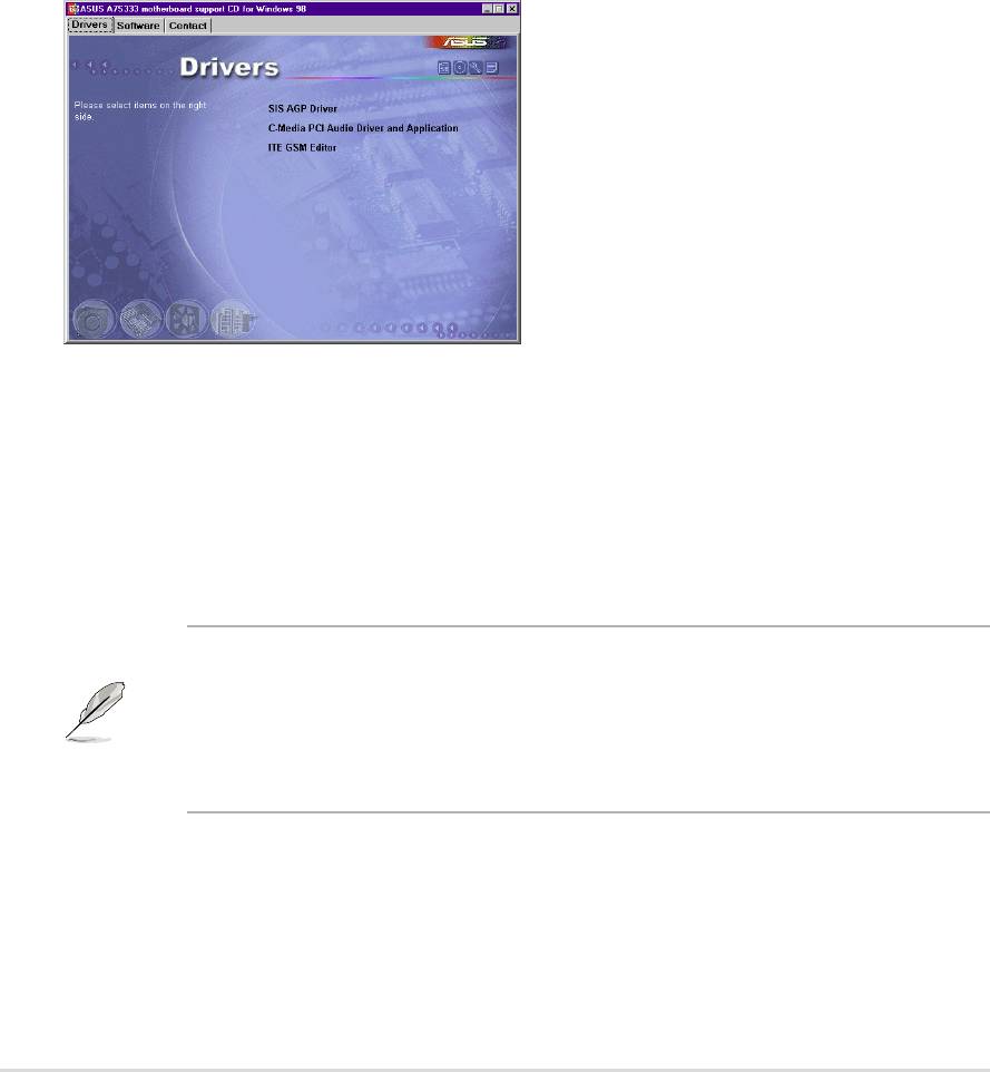
5.3.2 Available Installation Menus
Drivers:
• SiS AGP Driver: Installs the display drivers.
• C-Media PCI Audio Driver and Application: Installs the drivers for the
C-Media Audio Driver and the sound system to support the C-Media
Audio Chip and HRTF 3D Audio circuitry.
• ITE GSM Editor: Installs the GSM SIM card editing application.
NOTE: It is not advisable to install any software contained on the support
CD which does not appear on the setup menu. The ITE GSM Editor will
only appear if you have adjusted the I/O Device Configuration sub-menu
in the Advanced BIOS, go to the UART2 field and select Smart Card
Read.
78
Chapter 5: Software support
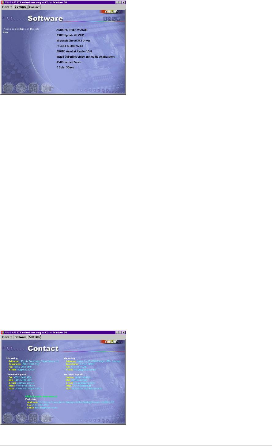
Software:
• ASUS PC Probe: Installs a smart utility to monitor your computer’s fan,
temperature, and voltages.
• ASUS Update: Instals a program that can help you update BIOS or
download a BIOS image file.
• Microsoft DirectX Driver: Installs basic drivers to enable compatibility
with audio and other special functions.
• PC-Cillin 2000: Installs the PC-cillin virus protection software. View online
help for more information.
• ADOBE Acrobat Reader: Installs the Adobe Acrobat Reader software
necessary to view user’s manuals saved in PDF format. Updated or other
language versions of this motherboard's manual is available in PDF format
at any of our web sites.
• Install Cyberlink Video and Audio Applications: Installs Cyberlink
PowerPlayer SE and Cyberlink VideoLive Mail.
• ASUS Screen Saver: Installs a nifty ASUS screen saver.
• E-Color 3Deep: Installs graphical driver and an application for tuning
the quality of color output from CRT and LCD monitors.
Contact:
• A detailed list of addresses, phone numbers and website locations
is available to help users access the information that they need.
ASUS A7S333 motherboard user guide
79

80
Chapter 5: Software support
5.4 ASUS PC Probe
ASUS PC Probe is a convenient utility to continuously monitor your
computer system’s vital components, such as fan rotations, Voltages, and
temperatures. It also has a utility that lets you review useful information about
your computer, such as hard disk space, memory usage, and CPU type,
CPU speed, and internal/external frequencies through the DMI
Explorer.
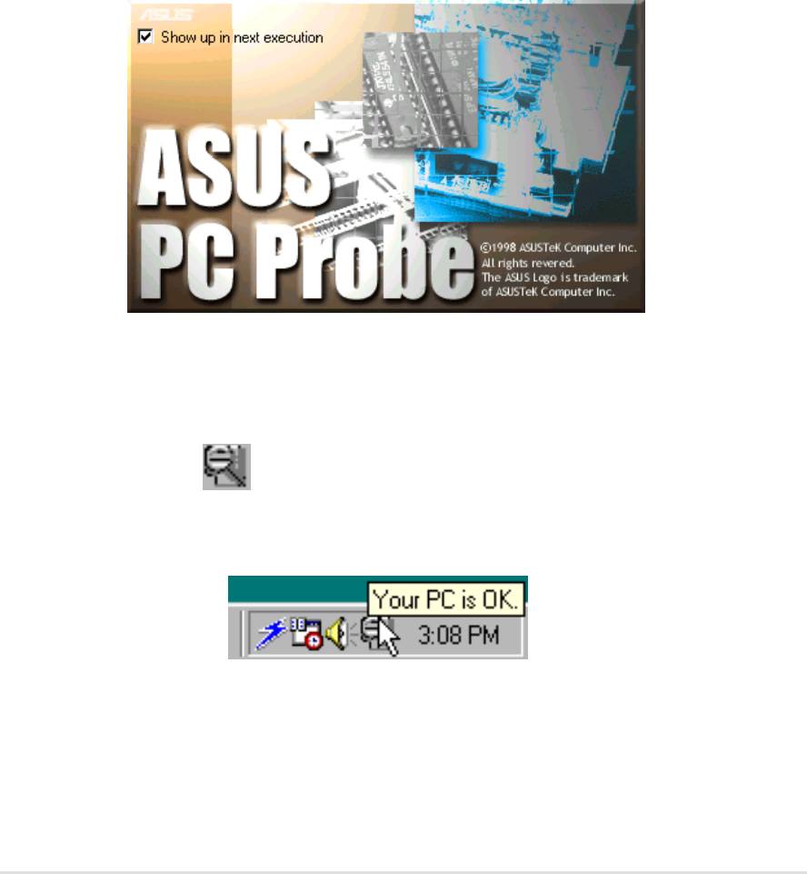
5.4.1 Starting ASUS PC Probe
When ASUS PC Probe starts, a splash screen appears allowing you to select
whether or not to show the screen the next time you open PC Probe. To
bypass this startup screen, clear the Show up in next execution check
box.
To start ASUS PC Probe, click the Windows Start button, point to Programs,
and then ASUS Utility, and then click Probe Vx.xx.
The PC Probe icon
will appear on the taskbar’s system tray indicating
that ASUS PC Probe is running. Clicking the icon will allow you to see the
status of your PC.
ASUS A7S333 motherboard user guide
81
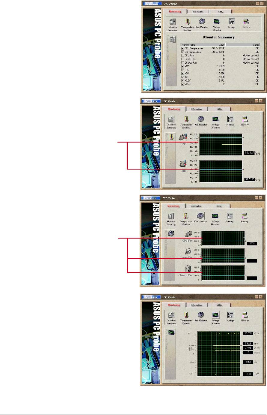
5.4.2 Using ASUS PC Probe
Monitoring
Monitor Summary
Shows a summary of the items being
monitored.
Temperature Monitor
Shows the PC’s temperature.
Temperature Warning
threshold adjustment
(Move the slider up to increase the
threshold level or down to decrease
the threshold level)
Fan Monitor
Shows the PC’s fan rotation.
Fan Warning
threshold adjustment
(Move the slider up to increase the
threshold level or down to decrease
the threshold level)
Voltage Monitor
Shows the PC’s voltages.
82
Chapter 5: Software reference
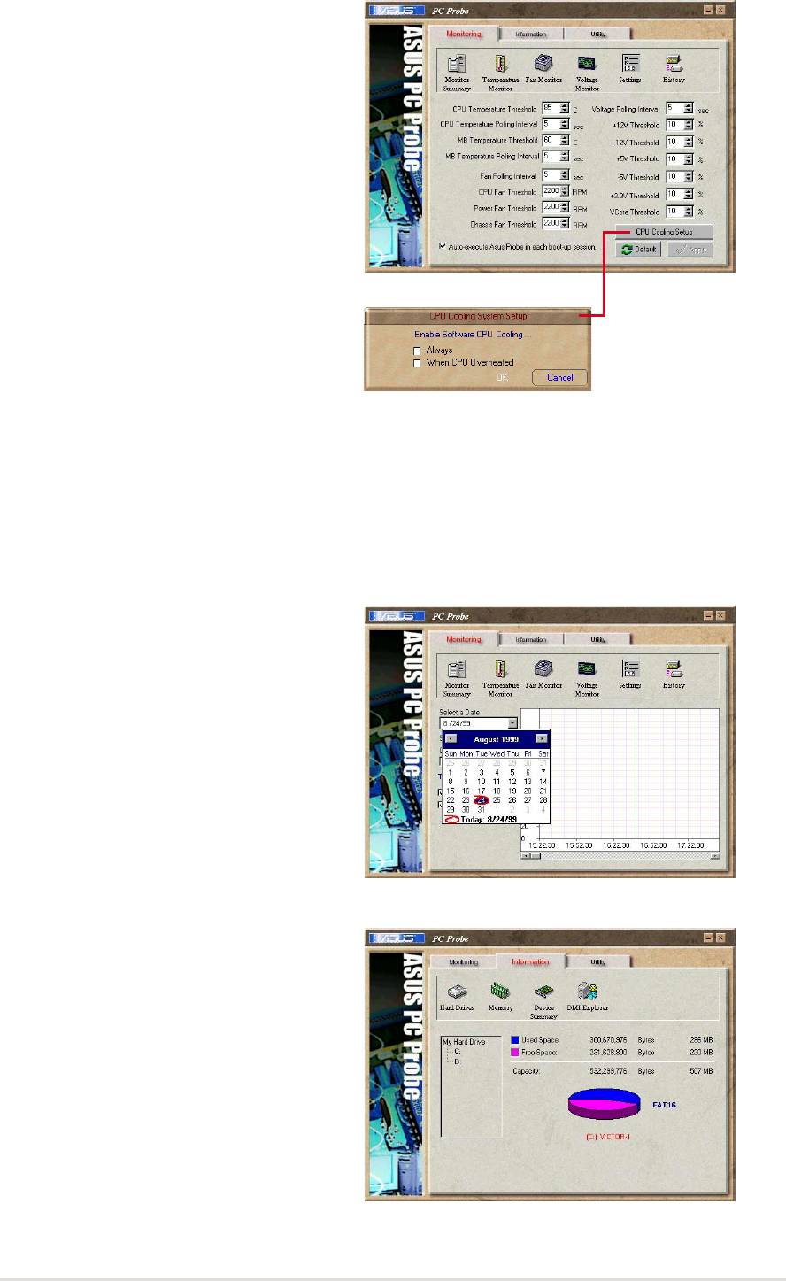
Settings
Lets you set threshold levels and
polling intervals or refresh times of
the PC’s temperature, fan rotation,
and voltages.
CPU Cooling System Setup
Lets you select when to enable
software CPU cooling. When When
CPU Overheated is selected, the
CPU cooling system is enabled
whenever the CPU temperature
reaches the threshold value.
History
Lets you record the current
monitoring activity of a certain
component of your PC for future
reference.
Information
Hard Drives
Shows the used and free space of
the PC’s hard disk drives and the file
allocation table or file system used.
ASUS A7S333 motherboard user guide
83
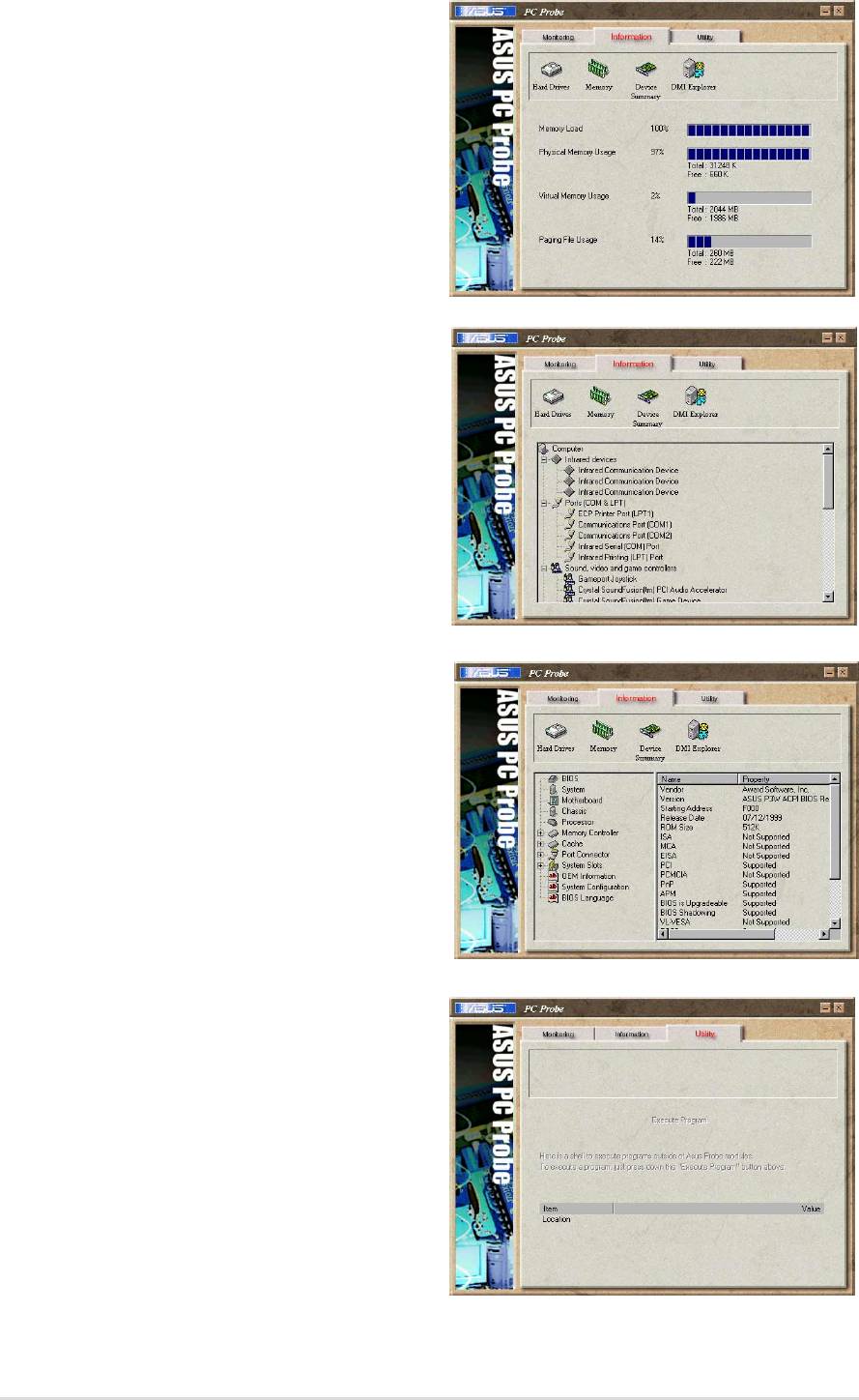
Memory
Shows the PC’s memory load,
memory usage, and paging file
usage.
Device Summary
Shows a summary of devices in your
PC.
DMI Explorer
Shows information pertinent to the
PC, such as CPU type, CPU speed,
and internal/external frequencies,
and memory size.
Utility
Lets you run programs outside of the
ASUS Probe modules. To run a
program, click Execute Program.
84
Chapter 5: Software reference

5.4.3 ASUS PC Probe Task Bar Icon
Right-clicking the PC Probe
icon will bring up a menu to
open or exit ASUS PC Probe
and pause or resume all
system monitoring.
When the ASUS PC Probe
senses a problem with your
PC, portions of the ASUS PC
Probe icon changes to red, the
PC speaker beeps, and the
ASUS PC Probe monitor is
displayed.
ASUS A7S333 motherboard user guide
85
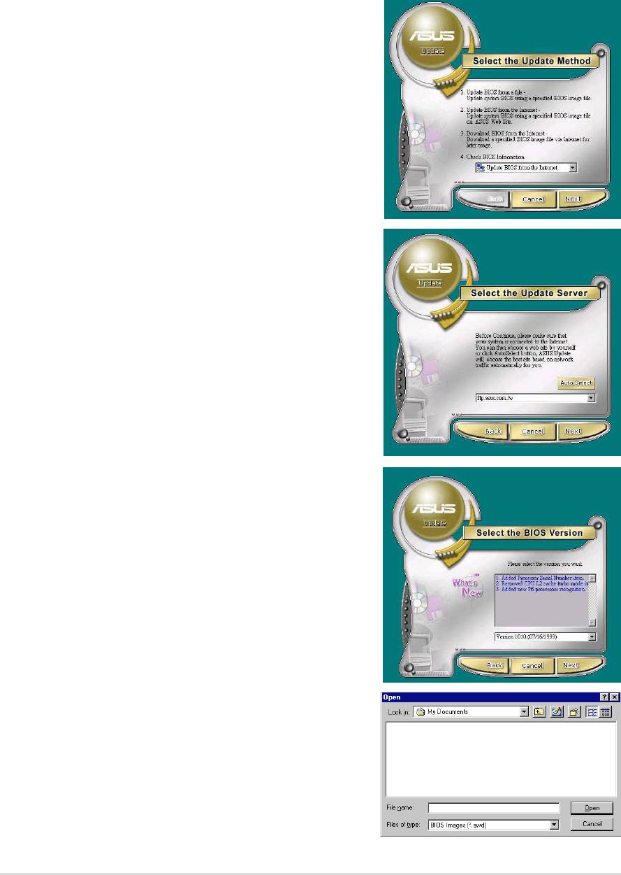
5.5 ASUS Live Update
ASUS LiveUpdate is a utility that allows you to update your motherboard’s
BIOS and drivers. The use of this utility requires that you are properly
connected to the Internet through an Internet Service Provider (ISP).
1. Start ASUS Update. Launch the
utility from your Windows Start
menu:Programs/AsusUpdate.
2. Select an update method.
3. If you selected “downloading from
the Internet,” you will need to select
an Internet site. Choose the site that
is closest to you or click Auto Select.
4. From the FTP site, select the BIOS
version that you wish to download.
Click Next.
5. Follow the instructions on the
succeeding screens to complete the
update process. If you selected the
option to update the BIOS from a file,
a window pops up prompting you to
locate the file. Select the file, click
Save, then follow the screen
instructions to complete the update
process.
86
Chapter 5: Software reference
5.6 3Deep Color Tuner
The 3-Deep color tuner is designed to match your CRT or LCD color
monitor to maximize the color quality of all graphical applications. Users
may also tune their internet applications to match “true” internet source colors
with the color displayed on the monitor.
Simply run the setup program from the start menu and follow the instructions
on the various setup/test screens.
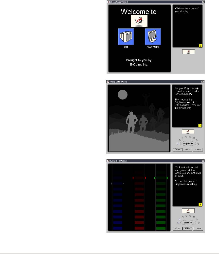
5.6.1 3Deep Color Tuning
1. Select the type of monitor
connected to the computer, either
CRT or LCD.
2. Follow the instructions to manually
adjust the brightness level of the
monitor.
3. Select the faintest of the three
colors: blue, red and green.
ASUS A7S333 motherboard user guide
87
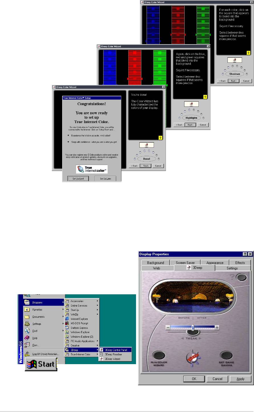
4. Select the color squares which
most closely blend and match with
the background.
5. The next step repeats
the color matching
process to achieve
full color quality.
6. The tuning process is complete. Click on the bottom left button to
connect to the internet and follow the instructions.
5.6.2 The 3Deep Control Panel
Using the Windows Start button, activate the 3Deep Control Panel
program from the 3Deep Applications group on the Main Program menu.
The control panel offers access to the
Color Wizard tuning program, a Game
Gamma setting and a Tweak slider for
brightness adjustment.
88
Chapter 5: Software reference
5.7 ITE GSM Editor
The ITE GSM Editor is a useful application for editing and managing the
data contained on a GSM cell phone SIM card chip. This unique software
supports access of the SIM card “phone book.” The editor helps you to add
or delete data including new names and phone numbers. The software also
enables advanced PIN management that includes changing the PIN plus
card-lock unblocking.
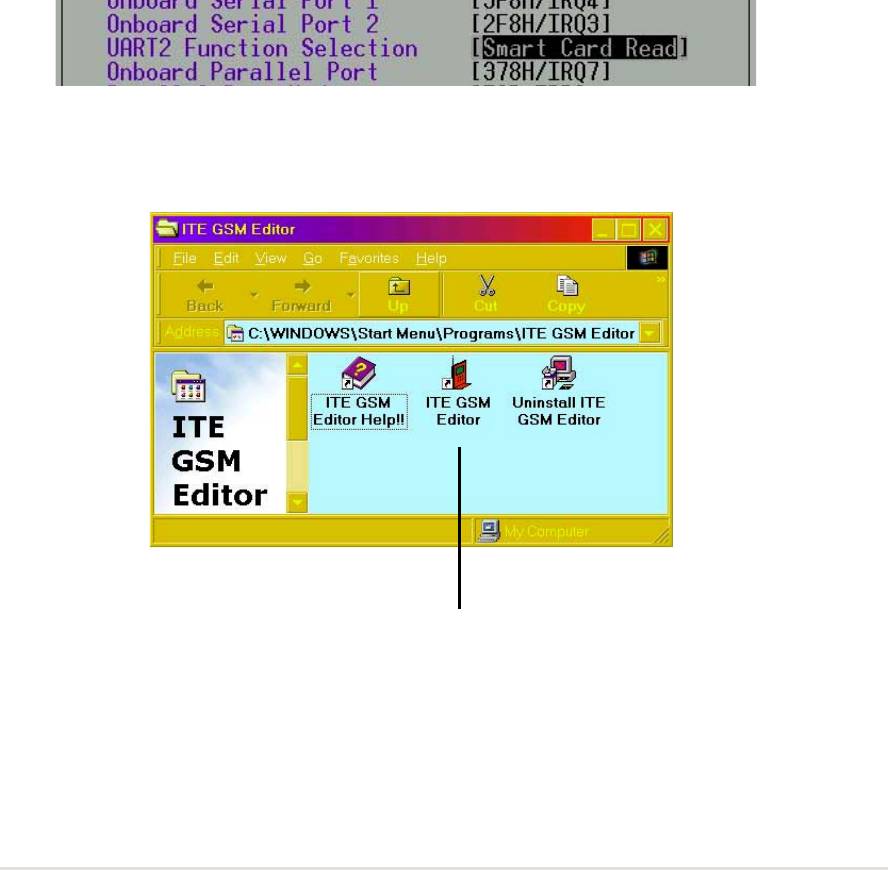
5.7.1 Setting Up ITE GSM Editor
Connect a smart card reader to the A7S333; (refer to page 36 in Hardware
Setup for the connector location.) Boot-up the PC and enter BIOS (press
<del>) to change the configuration to accept smart card hardware: in the
Advanced BIOS menu select the I/O Device Configuration sub-menu, go to
UART2 Function Selection and choose Smart Card Read, save and exit.
Finish booting up. Insert the ASUS Support CD and click on the selection:
ITE GSM Editor. The software is auto-installed to the program directory.
The new program group appears:
Click on the ITE GSM Editor Icon to start-up the program.
ASUS A7S333 motherboard user guide
89
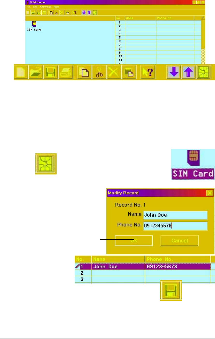
5.7.2 The ITE GSM Menu:
5.7.3 Using the basic ITE GSM Editor:
1. Carefully remove the SIM chip from your mobile phone and insert it into
the card reader. The most convenient method is to use a conversion card:
slip the SIM chip into the conversion card and then insert it into the card
reader.
2.To access the phone book contained in the SIM card,either click the chip
icon:
Or, double click the SIM Card:
3. To edit data, select the field
and double click it, or press
<Enter>. Type in the name
and number:
Then click OK
4. The data appears
in the field:
5. To save data to the SIM chip, click the save icon:
90
Chapter 5: Software reference
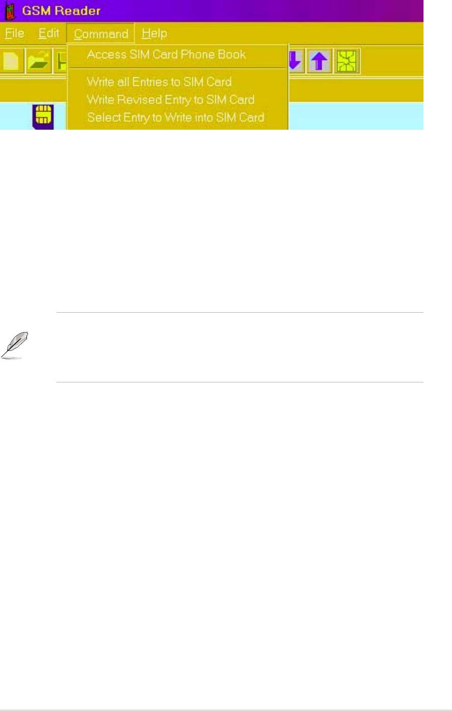
5.7.4 Using the Command field:
1. Write All Entries into SIM Card, and the program writes all new data
appearing in the fields onto the SIM card.
2. Write Revised Entry into SIM Card, and the program writes all updated
entries into the existing SIM card phone book. After revising the data, an
icon appears in front of the serial number indicated.
3. Select Entry to Write into SIM Card, and the program writes the selected
data from the open file into the SIM card database. Users can select multiple
entries by pressing <Ctrl> and mouse-selecting the data fields simultaneously.
Phone number entries may be comprised of: “1, 2, 3, 4, 5, 6, 7, 8, 9, #, *,
C, or +”. Pressing “C” commands the dialer to pause for three seconds
before dialing the next digit; the “C” code is useful for dialing extension
numbers. Pressing “+” indicates the international head code.
ASUS A7S333 motherboard user guide
91

5.7.5 Using the PIN Manager:
1. Enable PIN Set-Up: This function is used to set the PIN. This function is
effective only if the PIN set-up is disabled and the SIM card is not blocked.
First enter the PIN set previously to enable the PIN set-up function. New
users may find the default PIN in the SIM card user manual. If the correct
PIN numbers are entered, the SIM card can be reset. If three consecutive
attempts to enter the PIN fail, the SIM card is automatically blocked.
2. Disable PIN Set-Up: This function is used to disable the personal
identification number (PIN) set-up. It is effective only when the PIN set-up is
enabled and the SIM chip is not blocked. Users should first enter the current
PIN to disable the PIN set-up. If the correct PIN numbers are entered, the
SIM chip can be reset. If three consecutive attempts to enter the PIN fail, the
SIM chip is automatically blocked.
3. Unblock SIM Card: If the SIM chip is locked up, follow the steps below
to unlock it:
Step 1: To unblock, enter the PUK (Personal Unblocking Key) consult the
SIM chip support documentation for the key code. If the PUK code is not
supplied, contact the system operator/dealer.
Step 2: Enter a new PIN.
92
Chapter 5: Software reference
5.8 CyberLink PowerPlayer SE
CyberLink PowerPlayer SE is an intelligent software player that can
automatically detect and playback all kinds of video/audio files, CD and MP3
files as well. This is the only software you need for all types of video and
audio files. No need to waste time identifying your file types.
5.8.1 Starting CyberLink PowerPlayer SE
To start CyberLink Power Player, click the Windows Start button, point to
Programs, and then CyberLink PowerPlayer SE, and then click
PowerPlayer.
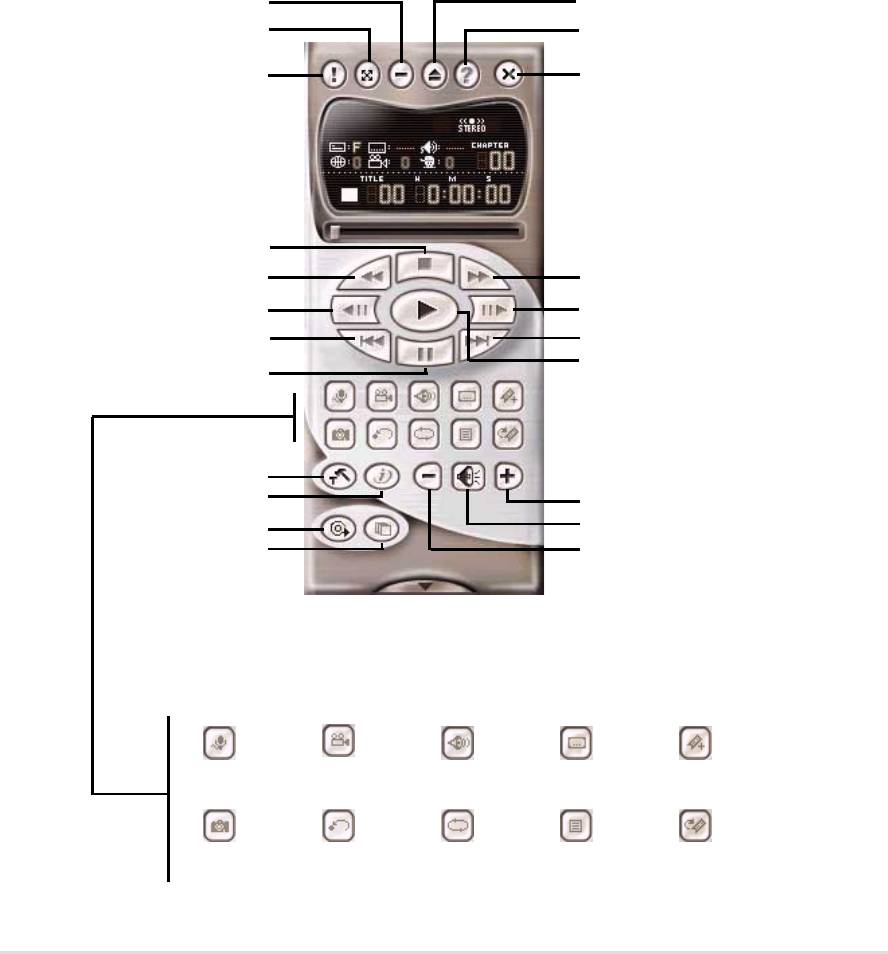
5.8.2 CyberLink PowerPlayer Control Panel
Minimize
Eject
Zoom
Help
About
Power Off
Stop
Backward Scan
Forward Scan
Backstep Frame
Step Frame
Previous
Next
Play
Stop
Configuration
i-Power!
Increase Volume
CD Mode
Mute
Shuffle
Decrease Volume
Karaoke Next angle Next audio stream Next subtitle Add bookmark
Capture frame Go-Up Repeat Menu Go to bookmark
ASUS A7S333 motherboard user guide
93

5.9 CyberLink VideoLive Mail
CyberLink’s VideoLive Mail Plus Ver 3.0 (a.k.a. VLM 3) is a convenient and
excellent way to create professional quality video mails from PC video/audio
input devices and to send the mails to any recipients via VLM 3’s built-in e-
mail system through the Internet. VLM 3’s mails comprise video, sound, or
snapshot information; and thus may convey the most profound information
to target audiences. It is very convenient for mail recipients who do not need
to install additional software component in order to view VLM 3 mails.
VLM 3 works as a very applicant sales tool. It efficiently delivers profound
and live product information to your target customers without costing a fortune.
VLM 3 also helps corporate managers easily give vivid speeches and
broadcast through corporate E-mail system. For personal or home users,
VLM 3 easily records live video clips allowing users to send them to friends
or family members across the Internet.
VLM 3 loads video messages from PC cameras, digital camcorders, analog
camcorder via video capture cards, or from an existing AVI video clips, and
captures audio messages from PC microphones. Video and audio messages
are encoded at a very high compressed rate in a real-time mode. From data
input, data conversion, to sending video mails via Internet, or saving data to
disks, the whole procedure is done in an easy and continuous process.
VLM 3’s video clip compression rate is up to 1:900, and its playback rate is
up to 30 frame per second. VLM 3 provides CIF (352 x 288 pixel) display
resolution, and support true color configuration. A one-minute video mail
with QCIF (176 x 144) resolution takes up less than 500KB of memory, making
it easy to transmit and save mail. Users may always adjust resolution and
recording parameters for different purpose.
VLM 3 supports all the hardware devices that are compliant with Video for
Windows standard. Video for Windows is a well-accepted and well-tested
standard. Thus, users do not have to worry about compatibility issues.
94
Chapter 5: Software reference
5.9.1 Starting VideoLive Mail
To start VideoLive Mail, click the Windows Start button, point to Programs,
and then CyberLink VideoLive Mail, and then click VideoLive Mail x.x.
VLM 3’s Setup Wizard will start and guide you through configuring the video
and audio input peripherals and to setup the e-mail environment.
1. Setup Wizard first will prompt a dialog to confirm that you want to configure
the hardware and E-mail setting. Click Yes to continue the system parameter
configuration.
2. The e-mail configuration screen appears. You will need to enter your
name and the e-mail address. Click Next to continue.
3. The Internet e-mail configuration screen appears. You may choose to use
the VLM 3 built-in E-mail functionality (SMTP mail), or use MAPI compliant
e-mail system. Consult your ISP or MIS staff for the E-mail server IP address
if you are not sure. Click Next to continue.
4. Then the Video Configuration screen shows up. You may have to specify
the video driver for VLM 3, if there are several video-input devices installed.
Then configure the number of video frames to be captured per second. Note
that the more frames you choose, the bigger the file size will be. Click Next
to continue.
5. Then the Setup Wizard will then search for the GSM CODECS module for
audio compression, and prompt you with the result. Click Next to continue.
6. Setup Wizard then tests the audio volume during playing and recording.
Click Next when ready.
7. Configuration done. Click Finish to complete the environmental setting
procedure.
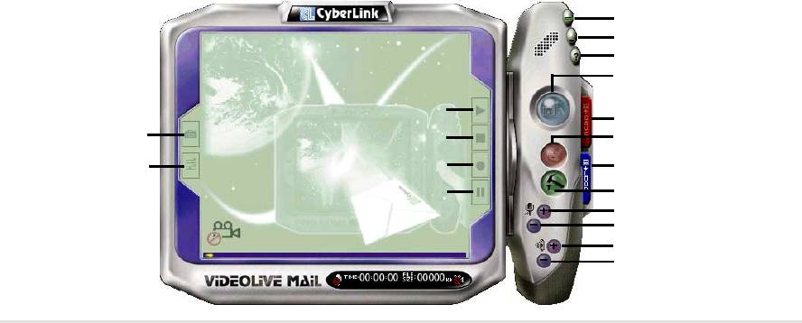
5.9.2 CyberLink VideoLive Mail User Interface
Exit
Minimize
Help
Video Mail Wizard
Start Playback
Save Video File
Snapshot to File
Stop Recording / Playback
Send Mail
Video Configuration
Start Recording
Load Video File
Pause
Send Mail
Increase MIC volume
Decrease MIC volume
Increase speaker volume
Decrease speaker volume
ASUS A7S333 motherboard user guide
95

96
Chapter 5: Software reference
