Asus A7S8X-MX: Chapter 2
Chapter 2: Asus A7S8X-MX
Chapter 2
Hardware information

ASUS A7S333 motherboard
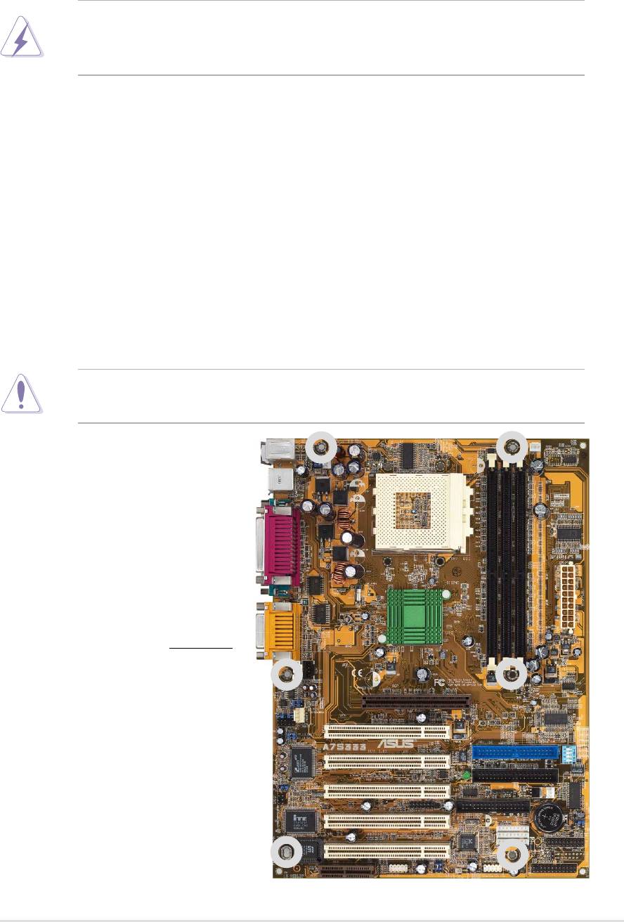
2.1 Motherboard installation
The A7S333 uses the ATX form factor, measuring 21.9 cm (8.6 in.) x 30.5 cm
(12 in.) - a standard fit for most large chassis.
WARNING! Unplug the power cord before installing the motherboard.
Failure to do so may cause you physical injury and damage motherboard
components.
2.1.1 Placement direction
When installing the motherboard, take care to orient the chassis correctly:
The edge with external ports goes to the rear part of the chassis. Refer to the
image below. It may be more convenient to install major cables, the CPU
and modular components before fixing the motherboard inside the case frame.
2.1.2 Screw holes
Place six (6) screws into the holes indicated by circles to secure the
motherboard to the chassis.
CAUTION! Do not overtighten the screws! Doing so may damage the
motherboard.
Place this side towards
the rear of the chassis
ASUS A7S333 motherboard user guide
7
24cm (9.4in)
PS/2KBMS
PWR_FAN
T: Mouse
KBPWR
B: Keyboard
CPU_FAN
USBPWR_12
USB
T: USB1
B: USB2
COM1
Socket 462
PARALLEL PORT
COM2
SiS
Line
Out
745
DDR DIMM1 (64/72 bit, 184-pin module)
DDR DIMM2 (64/72 bit, 184-pin module)
DDR DIMM3 (64/72 bit, 184-pin module)
ATX Power Connector
Line
Chipset
In
Mic
GAME_AUDIO
In
0 1
2 3
4 5
CDAUX
BCS1
30.5cm (12.0in)
BCS2
Accelerated Graphics Port
AGP
FP_LINE_IN
MODEM
FP_AUDIO
PCI1
FP_LO_SWR
FP_LO_SWL
®
PRI_IDE
A7S333
DSW
PCI2
SEC_IDE
C-Media
CMI8738 6CH
Audio Controller
LED
AUDIO_EN
PCI3
SMB
FLOPPY
CHA_FAN
SPDIF
SMARTCON
CR2032 3V
Lithium Cell
Super
PCI4
CMOS Power
I/O
CLRTC
RTL8801
JEN
2Mbit
IEEE1394_3
Firmware
PCI5
PANEL
Hub
IEEE1394_2
IDELED
USBPWR_56
IEEE1394_1
AMR
USBPWR_34
USB_56
USB_34
AFPANEL
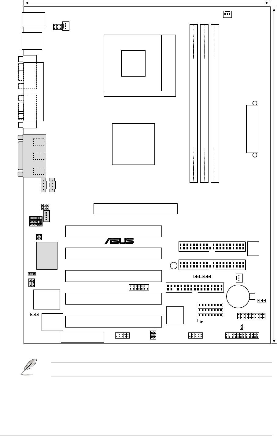
Optional components are grayed in the above motherboard layout.
8
Chapter 2: Hardware information

2.2.1 Layout contents
CPU, Memory and Expansion Slots
1) Socket 462 p. 12 CPU Support
2) DIMM 1/2/3 p. 14 System Memory Support
3) PCI 1/2/3/4/5 p. 19 32-bit PCI Bus Expansion Slots
4) AGP 4x p. 19 Accelerated Graphics Slot
5) AMR p. 20 Audio Modem Riser Slot (Optional)
Motherboard Settings (Switches and Jumpers)
1) JEN p. 21 JumperFree Mode Setting (Disable/Enable)
2) DIP_SW p. 21 CPU and DRAM Frequency Selection
(Switches 1–4)
3) KBPWR p. 23 Keyboard Wake Up (+5V / +5VSB)
4)
USBPWR12, 34, 56
p. 24 USB Device Wake-up (Disable/Enable)
5) BCS1, BCS2 p. 25
Bass Center Setting
(Center/Bass, Bass/Center)(Optional)
6) AUDIO_EN p. 25 Onboard Audio Setting (Disable / Enable)
(Optional)
7) CLRTC p. 26 Clear RTC RAM
Connectors
1) PS2KBMS p. 27 PS/2 Mouse Port (6 pin female)
2) PS2KBMS p. 27 PS/2 Keyboard Port (6 pin female)
3) USB_12 p. 28 U
niversal Serial Bus Ports 0, 1, 2 (Two x 4 pin female)
4) LPT p. 28 Parallel Port (25 pin female)
5) COM1/COM2 p. 28 Serial Ports (Two x 9 pin male)
6) GAME_AUDIO p. 29 Game/MIDI Ports (Gold 15-pin) (Optional)
7) AUDIO p. 29 Audio Connectors (Three 1/8” AUDIO) (Optional)
8) IDE_LED p. 30 IDE Activity LED (2 pin)
9) FLOPPY p. 30 Floppy Disk Drive Connector (34-1 pin)
10) PRI_, SEC_IDE p. 31 IDE Connectors (Two 40-1 pin)
11)
CPU_,PWR_,CHA_FAN
p. 32
CPU, Power, and Chassis Fan Connectors (Three 3 pin)
12) AFPANEL p. 33 ASUS iPanel / Infrared Connector (24-1 pin)
13) ATXPWR p. 34 ATX Power Supply Connector (20 pin)
14) SMB p. 34 SMBus Connector (5-1 pin)
15) CD / AUX / MODEM p. 35 Internal Audio Connectors
(Three 4-1 pin) (Optional)
16) FP_AUDIO p. 35
Front Panel Audio Connector (10-1 pin)
(Optional)
17) SMARTCON p. 36 Smart Card Reader Connector (14-1 pin)
18) 1394HEAD_1, 2, 3 p. 36 IEEE-1394 Header (Three x 8-pin ) (Optional)
19) SPDIF p. 37 Digital Audio Interfaces (6-1 pin) (Optional)
20) USB_34, _56 p. 37 USB Headers (Two 10-1 pin)
21) FP_Line_In p. 38 Line-in Connecters (5 pin) (Optional)
ASUS A7S333 motherboard user guide
9

22) PLED (PANEL) p. 39 System Power LED Lead (3-1 pin)
23) SPEAKER (PANEL) p. 39 System Warning Speaker Lead (4 pin)
24) MLED (PANEL) p. 39 System Message LED Lead (2 pin)
25) SMI (PANEL) p. 39 System Management Interrupt Lead (2 pin)
26) PWRBTN PANEL) p. 39 ATX / Soft-Off Switch Lead (2 pin)
27) RESET (PANEL) p. 39 Reset Switch Lead (2 pin)
10
Chapter 2: Hardware information
2.3 Before you proceed
Take note of the following precautions before you install motherboard
components or change any motherboard settings.
CAUTION!
1. Unplug the power cord from the wall socket before touching any
component.
2. Use a grounded wrist strap or touch a safely grounded object or to a
metal object, such as the power supply case, before handling
components to avoid damaging them due to static electricity.
3. Hold components by the edges and do not to touch the ICs on them.
4. Whenever you uninstall any component, place it on a grounded
antistatic pad or in the bag that came with the component.
5. Before you install or remove any component, ensure that the
ATX power supply is switched off or the power cord is detached
from the power supply. Failure to do so may cause severe damage
to the motherboard, peripherals, and/or components.
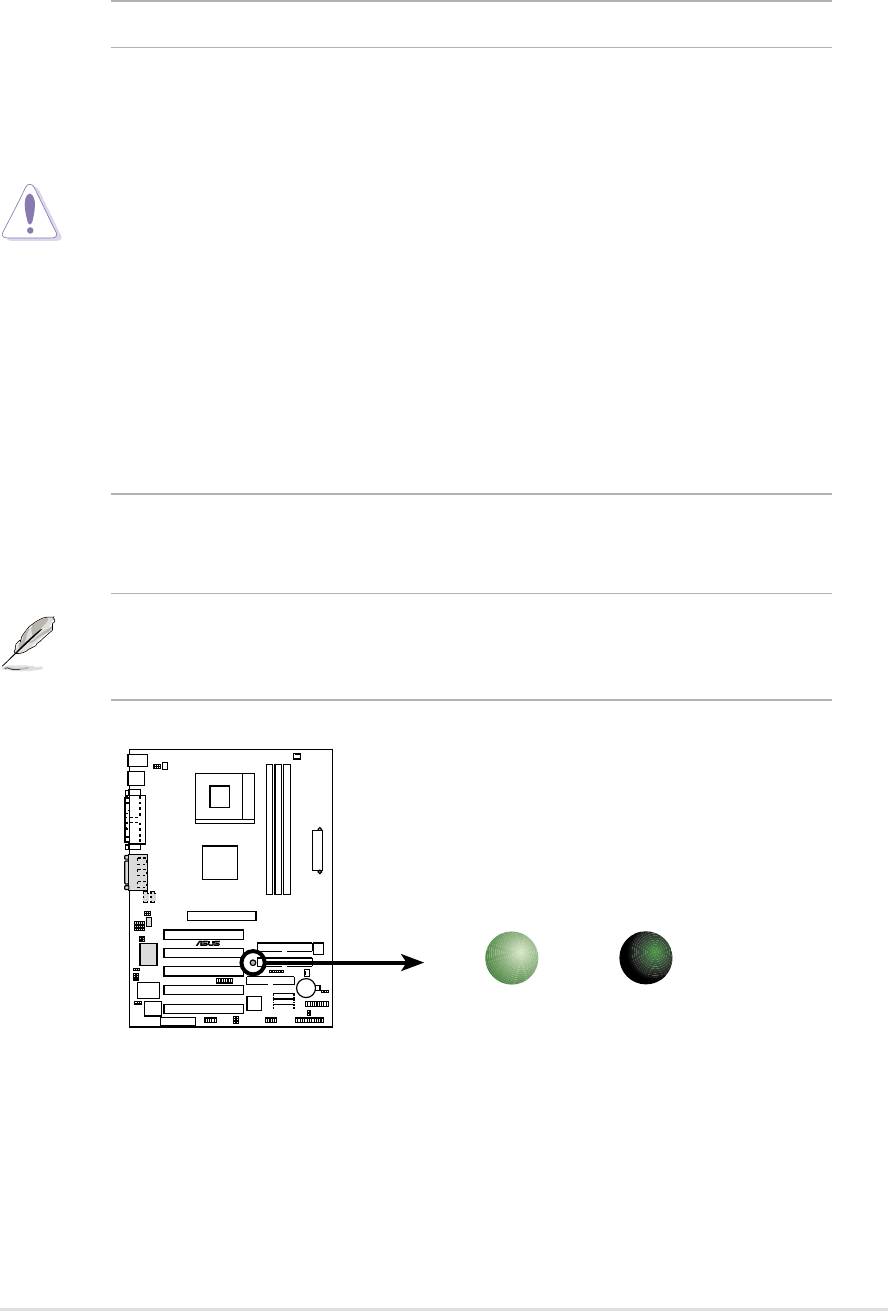
NOTE! When lit, the onboard LED indicates that the system is ON, in
sleep mode or in soft-off mode, not powered OFF. See the illustration
below.
SB_PWR
A7S333
®
ON
OFF
Standby
Powered
Power
Off
A7S333 Onboard LED
ASUS A7S333 motherboard user guide
11
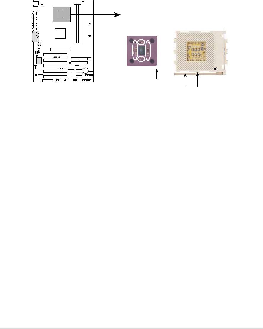
2.4 Central Processing Unit (CPU)
2.4.1 Overview
The motherboard provides a Socket A (462) for CPU installation. AMD
processors offer gigahertz speeds to support all the latest computing platforms
™
and applications. The A7S333 supports Athlon
XP processors with
“QuantiSpeed” data processing, large data caches, 3D enhancements and
266Mhz bus speeds.
CPU NOTCH
TO INNER
CORNER
AMD™ CPU
A7S333
®
CPU NOTCH
A7S333 Socket A
LEVER
LOCK
Each AMD CPU has a “marked” corner. This corner is usually indicated with
a notch, and/or a golden square or triangle. Refer to this indicator while
orienting the CPU. See the next section for installation details.
A fan and heatsink should be attached to the CPU to prevent overheating.
12
Chapter 2: Hardware information
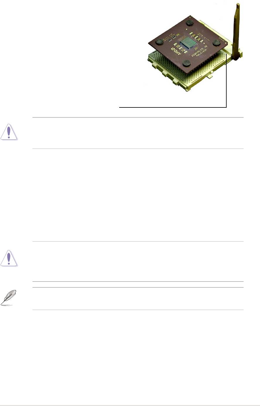
2.4.2 Installing the CPU
Follow these steps to install a CPU:
1. Locate the Socket 462 and open it by
pulling the lever gently sideways away
from the socket. Then lift the lever
upwards. The socket lever must be fully
opened (90 to 100 degrees).
2. Insert the CPU with the correct
orientation. The notched or golden
corner of the CPU must be oriented
toward the inner corner of the socket
base nearest to the lever hinge.
CAUTION! The CPU should drop easily into place. Do not force the
CPU into the socket to avoid bending the pins. If the CPU does not fit,
check its alignment and look for bent pins.
4. Once completely inserted, press the CPU firmly and close the socket
lever until it snaps shut.
5. Place the CPU fan and heatsink on the CPU. The heatsink should entirely
cover the CPU. Carefully attach the heatsink locking brace to the plastic
clips on the socket base. With the added weight of the CPU fan and
heatsink locking brace, no extra force is required to keep the CPU in
place
CAUTION! Take care not to scrape the motherboard surface when
mounting a clamp-style processor fan, or else damage may occur. When
mounting a heatsink onto your CPU, make sure that exposed CPU
capacitors do not touch the heatsink, or damage may occur!
NOTE! Do not neglect to set the correct Bus Frequency and leave the
CPU Multiple setting at default to avoid start-up problems.
ASUS A7S333 motherboard user guide
13
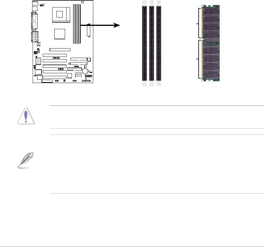
2.5 System memory
2.5.1 Overview
This motherboard uses only Double Data Rate (DDR) Synchronous Dynamic
Random Access Memory (SDRAM) Dual Inline Memory Modules (DIMMs).
These sockets support up to 3GB system memory using non-ECC , unbuffered
PC2700/PC2100/PC1600 DIMMs.
Each DIMM socket/module is two-sided: each side defines one “row” of
memory. DIMMs come in combinations of single or double-sided types
ranging through 64MB, 128MB, 256MB, 512MB and 1GB to form a total
memory size of 64MB to 3GB.
~ Three (3) sockets are available for both 266MHz-PC2100 or 200MHz-
PC1600 DDR DIMMs to form a memory size of 64MB to 3GB. Only two (2)
DIMMs will support 333MHz-PC2700; if more than two 333MHz DIMMs are
installed, the system automatically reverts to a maximum speed of 266MHz.
80 Pins
A7S333
®
104 Pins
A7S333 184-Pin DDR DIMM Sockets
CAUTION! DIMMs are keyed to fit into notches with only one direction.
DO NOT force a DIMM into a socket to avoid damaging the DIMM.
• DIMMs with more than 18 chips are not supported.
• ASUS motherboards support SPD (Serial Presence Detect)DIMMs.
This is the memory of choice for best performance vs. stability
• BIOS shows DDR SDRAM memory on bootup screen.
• This motherboard supports three pairs of differential clock signals
per DIMM.
14
Chapter 2: Hardware information
2.5.2 Memory configurations
Install DIMMs in any of the following combinations.
DIMM Location 168-pin DIMM (SDR) Total Memory
Socket 1 (Rows 0&1) 64MB, 128MB, 256MB, 512MB, 1GB x1
Socket 2 (Rows 2&3) 64MB, 128MB, 256MB, 512MB, 1GB x1
Socket 3 (Rows 4&5) 64MB, 128MB, 256MB, 512MB, 1GB x1
Total system memory (Max. 3GB PC2100 / PC1600) =
(Max. 2GB PC2700)
2.5.3 DDR333 DIMM Qualified Vendor List
The following table lists the PC2700 - DDR333 memory modules that have
been tested and qualified for use with this motherboard.
Vendor Model Type/Size
Nanya NT5DS16M8AT-6 PC2700/256MB
Samsung K4H280838D-TCB3 PC2700/128MB
Samsung K4H280838D-TCB3 PC2700/256MB
Micron MT8VDDT1664AG-335B1 PC2700/128MB
Micron MT16VDDT3264AG-335B1 PC2700/256MB
KINGMAX MPMA82D-68KX3 PC2700/128MB
KINGMAX MPM62D-68KX3 PC2700/256MB
Use only the tested and qualified PC2700 - DDR333 DIMMs listed
above. Other DDR DIMMs manufactured by other vendors may not be
suitable for this motherboard. Visit the ASUS website for the latest
qualified DDR module list.
ASUS A7S333 motherboard user guide
15
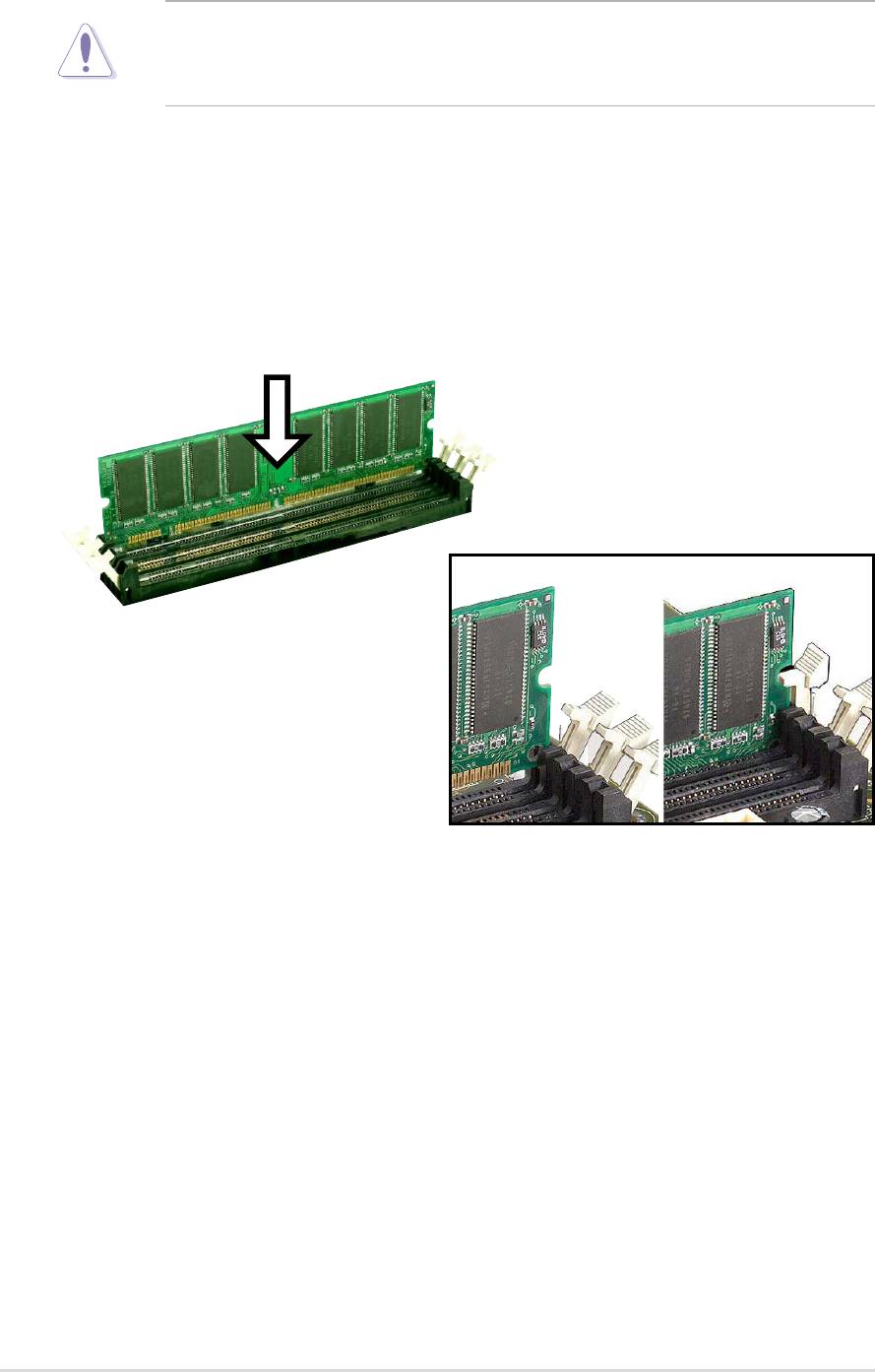
2.5.4 Installing a DIMM
CAUTION! Make sure to unplug the power supply before adding or
removing DIMMs or other system components. Failure to do so may cause
severe damage to both the motherboard and the components.
Installing a DIMM:
1. Unlock a DIMM socket by pressing the retaining clips outward.
2. Align a DIMM on the socket such that the notches on the DIMM exactly
match the notches in the socket.
3. Firmly insert the DIMM into the socket until the retaining clips snap back
in place.
Unlocked Retaining Clip Locked Retaining Clip
16
Chapter 2: Hardware information
2.6 Expansion slots
The motherboard has five PCI slots and one Accelerated Graphics Port (AGP)
slot and oen AMR slot. The following sub-sections describe the slots and the
expansion cards that they support.
WARNING! Unplug your power supply when adding or removing
expansion cards or other system components. Failure to do so may cause
you physical injury and damage motherboard components.
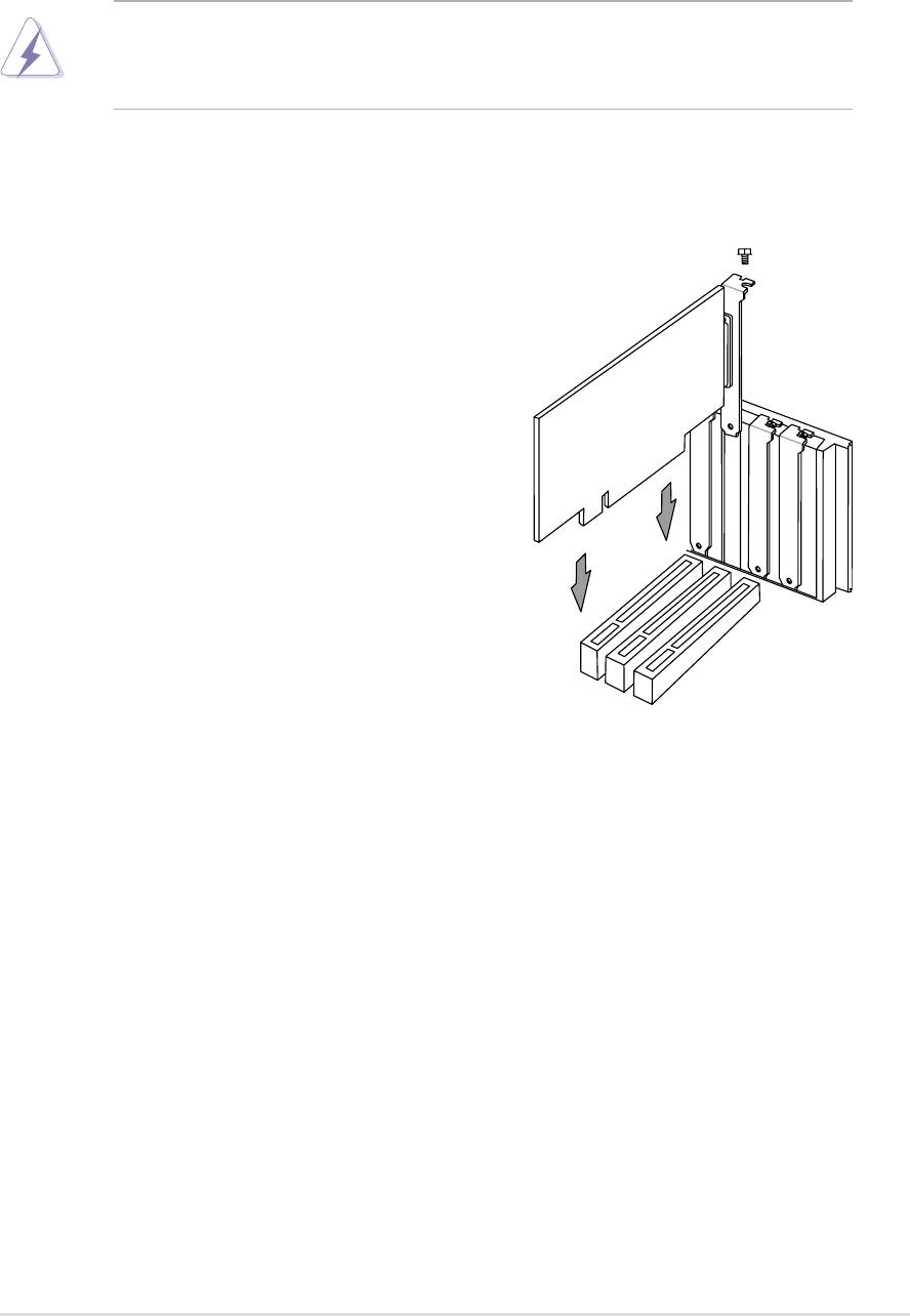
2.6.1 Installing an expansion card
Follow these steps to install an expansion
card.
1. Before installing the expansion card, read
the documentation that came with it and
make the necessary hardware settings.
2. Remove the system unit cover (if your
motherboard is already installed in a
chassis).
3. Remove the bracket opposite the PCI slot.
Keep the screw for later use.
4. Align the card connector with the slot and
press firmly until the card is completely
seated on the slot.
5. Secure the card to the chassis with the
screw you removed earlier.
6. Replace the system cover.
7. Set up the BIOS if necessary.
8. Install the necessary software drivers for your expansion card.
2.6.2 Configuring an expansion card
Some expansion cards need an IRQ to operate. Generally, an IRQ must be
exclusively assigned to one function at a time. In a standard design
configuration, 16 IRQs are available but most are already in use. Normally,
6 IRQs are free for expansion cards. If the motherboard has PCI audio
onboard, an additional IRQ will be used. If your motherboard also has MIDI
enabled, another IRQ will be used, leaving 4 IRQs free. Sometimes IRQs
are “shared” by more than one function; in this case, IRQ assignments are
swapped automatically or adjusted through the BIOS firmware.
ASUS A7S333 motherboard user guide
17
IMPORTANT! When using PCI cards on shared slots, ensure that the
drivers support “Share IRQ” or that the cards do not need IRQ
assignments. Otherwise, conflicts will arise between the two PCI groups,
making the system unstable and the card inoperative.
Standard Interrupt Assignments
IRQ Priority Standard Function
0 1 System Timer
1 2 Keyboard Controller
2 N/A Programmable Interrupt
3* 11 Communications Port (COM2)
4* 12 Communications Port (COM1)
5* 13 Sound Card (sometimes LPT2)
6 14 Floppy Disk Controller
7* 15 Printer Port (LPT1)
8 3 System CMOS/Real Time Clock
9* 4 ACPI Mode when used
10* 5 IRQ Holder for PCI Steering
11* 6 IRQ Holder for PCI Steering
12* 7 PS/2 Compatible Mouse Port
13 8 Numeric Data Processor
14* 9 Primary IDE Channel
15* 10 Secondary IDE Channel
*These IRQs are usually available for ISA or PCI devices.
Interrupt Request Table for this Motherboard
This table lists the default IRQ assignments fo rthis motherboard.
ABCDEFGH
PCI slot 1 shared ———————
PCI slot 2 — shared ——————
PCI slot 3 ——used —————
PCI slot 4 ———shared ————
PCI slot 5 ———shared ————
Onboard USB controller HC0———shared ————
Onboard USB controller HC1———————used
AGP shared ———————
Onboard Audio — shared ———used ——
18
Chapter 2: Hardware information
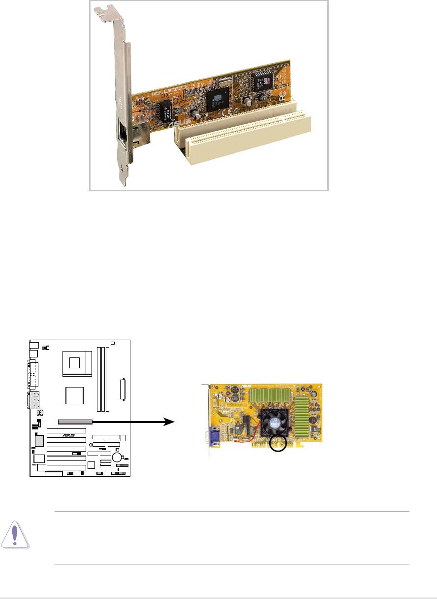
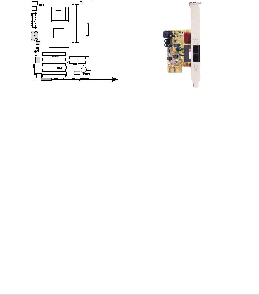
2.6.3 PCI slots
Five 32-bit PCI slots are available on this motherboard. The slots support
PCI cards such as a LAN card, SCSI card, USB card, and other cards that
comply with PCI specifications.
This figure shows a typical PCI card installed into a slot:
2.6.4 AGP slot
This motherboard provides an Accelerated Graphics Port (AGP 4X) slot to
support AGP graphics cards. Take note of the notches on the card golden
fingers to ensure that they fit the AGP slot on your motherboard. Below is an
example of a +1.5V AGP card.
A7S333
®
Keyed for 1.5v
A7S333 Accelerated Graphics Port (AGP)
CAUTION! To avoid damaging your AGP/AGP Pro graphics card, your
computer’s power supply should be unplugged before inserting your
graphics card into the slot.
ASUS A7S333 motherboard user guide
19
2.6.5 AMR slot (Optional)
The Audio Modem Riser (AMR) slot supports interface cards that integrate
audio, modem, and network functions.
This connector supports a specially designed audio and/or modem card
called an AMR. Main processing is done through software and controlled by
the motherboard’s system chipset. This provides an upgradeable audio and/
or modem solution at an incredibly low cost. There are two types of AMR,
one defined as primary and another defined as secondary. You can only use
primary AMRs with this motherboard.
NOTE: An AMR is not included with this motherboard.
A7S333
®
A7S333 Audio Modem Riser (AMR) Connector
20
Chapter 2: Hardware information
2.7 Switches and jumpers
The jumpers and switches on the motherboard allow you to change some
feature settings to suit your customized system configuration.
Motherboard Frequency Settings (DSW Switches)
The motherboard frequency is adjusted through the DSW switches.
The illustration below shows the default position:
DSW
1234
ON
A7S333
®
ON
OFF
1.Frequency Selection
2.Frequency Selection
3.Frequency Selection
A7S333 DIP Switches
4.Frequency Selection
IMPORTANT! To use the DSW switches to make changes to speed
settings, the JEN jumper must be reset to pins 1-2 for jumper mode.
Otherwise, setting the DSW switches does not produce any effect.
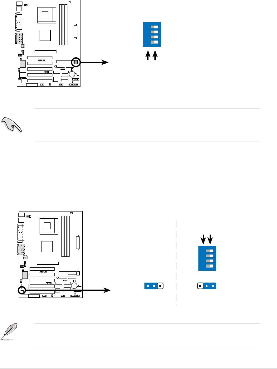
1) JumperFree™ Mode (3 pin JEN)
This jumper allows you to enable or disable the JumperFree™ mode. The
JumperFree™ mode allows processor settings to be made through the BIOS
setup.
JEN
DSW
ON
OFF
1234
A7S333
®
ON
12
2
3
Jumper Mode
Jumper Free
(Default)
A7S333 JumperFree™ Mode Setting
NOTE! The JEN jumper is set in conjunction with the DIP switches. In
JumperFree™ mode, set all DIP switches (DIP_SW) to OFF.
ASUS A7S333 motherboard user guide
21
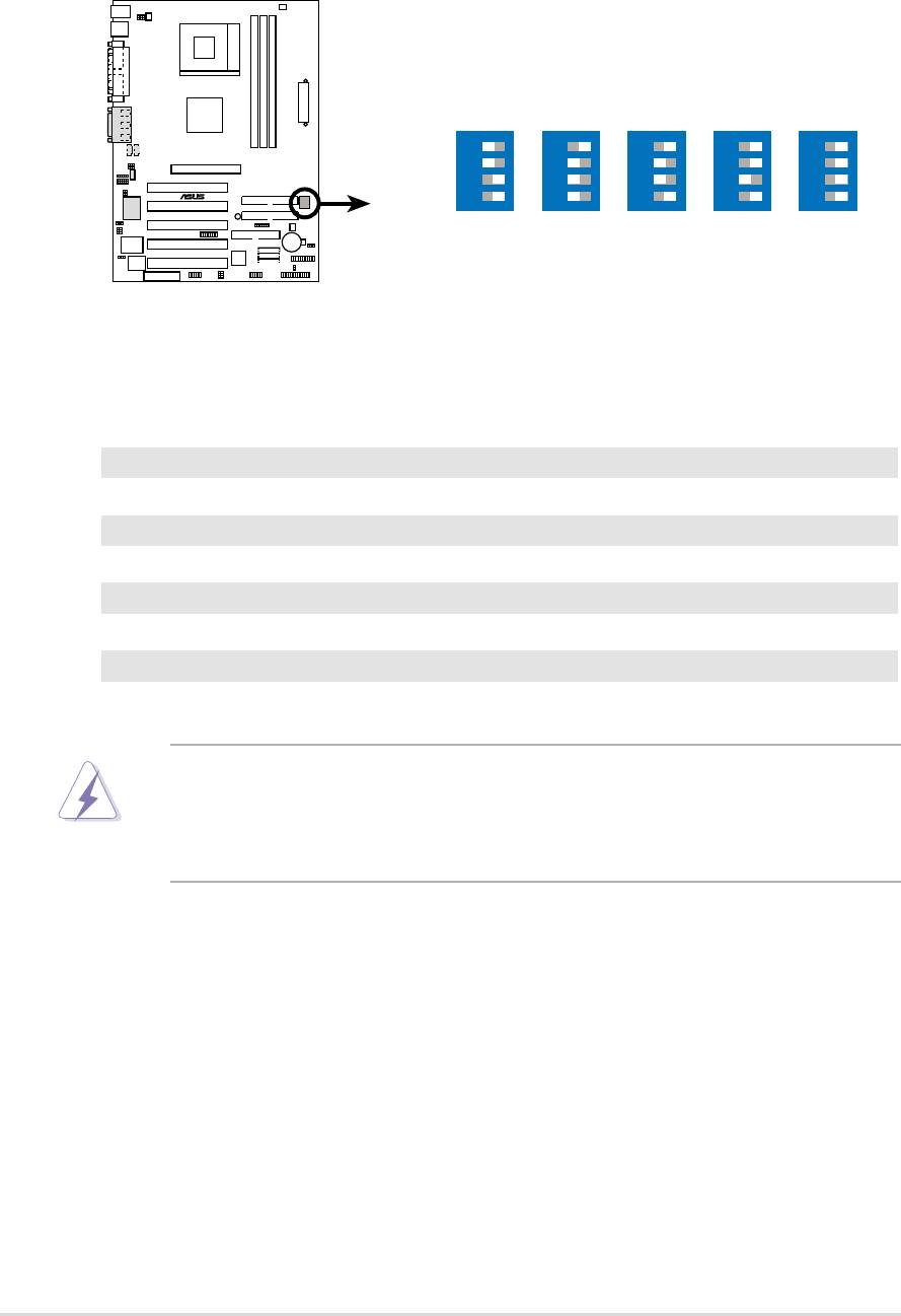
2) CPU and DRAM Frequency Selection (DIP_SW Switches 1–4)
This option tells the clock generator what frequency to send to the CPU,
DRAM, and the PCI bus, permiting selection of the CPU’s External frequency
(or, BUS Clock) and the DRAM memory speed.
DSW
A7S333
®
1234
1234
1234
1234
1234
ON
ON
ON
ON
ON
CPU
133MHz
100MHz
133MHz
133MHz
100MHz
DRAM
166MHz
133MHz
100MHz
133MHz
100MHz
A7S333 CPU
External Frequency Selection
Frequency Table
DSW
CPU DRAM 1 2 3 4
133 166 [OFF] [OFF] [ON] [ON]
100 133 [ON] [ON] [ON] [OFF]
133 100 [OFF] [ON] [ON] [OFF]
133 133 [OFF] [ON] [OFF] [OFF]
100 100 [OFF] [OFF] [OFF] [OFF]
WARNING! Set the CPU frequency only to the recommended settings.
Frequencies other than the recommended CPU bus frequencies are not
guaranteed to be stable. Overclocking the processor is not recommended.
It may result in a slower speed.
22
Chapter 2: Hardware information
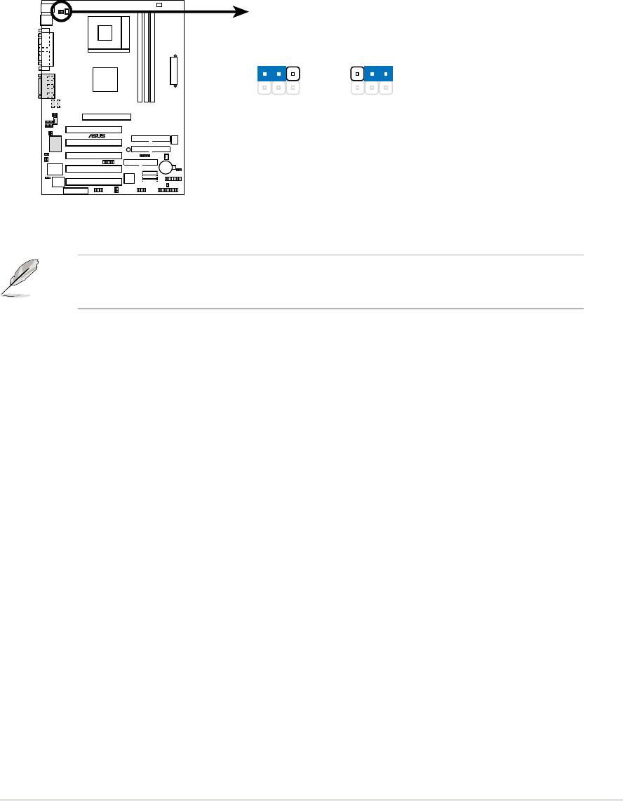
3) Keyboard Wake Up (3 pin KBPWR)
This allows you to disable or enable the keyboard power up function. This
jumper is set to [1-2], +5V, which disables keyboard power up. To enable
keyboard power up, change the jumper to [2-3], +5VSB. The keyboard
<Spacebar> can be used to power up the computer. This feature requires
an ATX power supply that can supply at least 300mA on the +5VSB lead.
(The computer will not power ON if you set this to [2-3] but do not have the
correct ATX power supply.)
KBPWR
12
23
+5V
+5VSB
(Default)
A7S333
®
A7S333 Keyboard Power Setting
NOTE! This jumper must be set in conjunction with Wake On PS2 KB/
PS2 Mouse/CIR in 4.5.1 Power Up Control.
ASUS A7S333 motherboard user guide
23
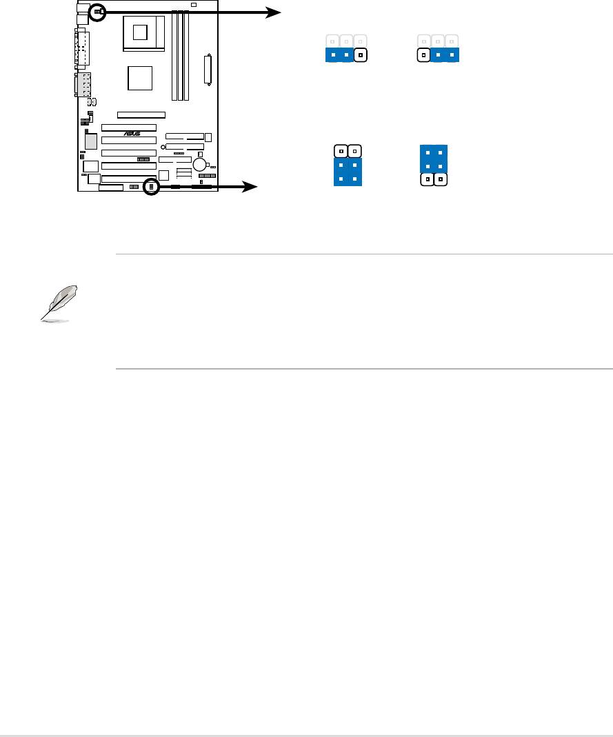
4) USB Device Wake-up (Three x 3 pin USBPWR_12, 34, 56)
Set these jumpers to +5V to allow wake up from the S1 sleep state (CPU
stopped; RAM refreshed; system running in low power mode) using the
connected USB devices. Set to +5VSB to allow wake up from S3 sleep state
(no power to CPU; RAM in slow refresh; power supply in reduced power
mode). The default setting for the three jumpers is [1-2] to select +5V (because
not all computers have the appropriate power supply).
The USBPWR_12 jumper activates device wake-up on the rear panel USB
ports. The USBPWR_34 jumper activates internal header, USB_34, and the
USBPWR_56 jumper activates header, USB_56.
USBPWR_12
12
23
+5V
+5VSB
(Default)
USBPWR_34
A7S333
®
USBPWR_56
3
2
2
1
+5V
+5VSB
A7S333 USB Device Wake Up
(Default)
NOTE! This feature requires an ATX power supply that can supply at
least 2A on the +5VSB lead when these jumpers are set to +5VSB.
Otherwise, the system does not power up. The total current consumed
must NOT exceed the power supply capability (+5VSB) whether under
normal working conditions or in sleep mode.
24
Chapter 2: Hardware information
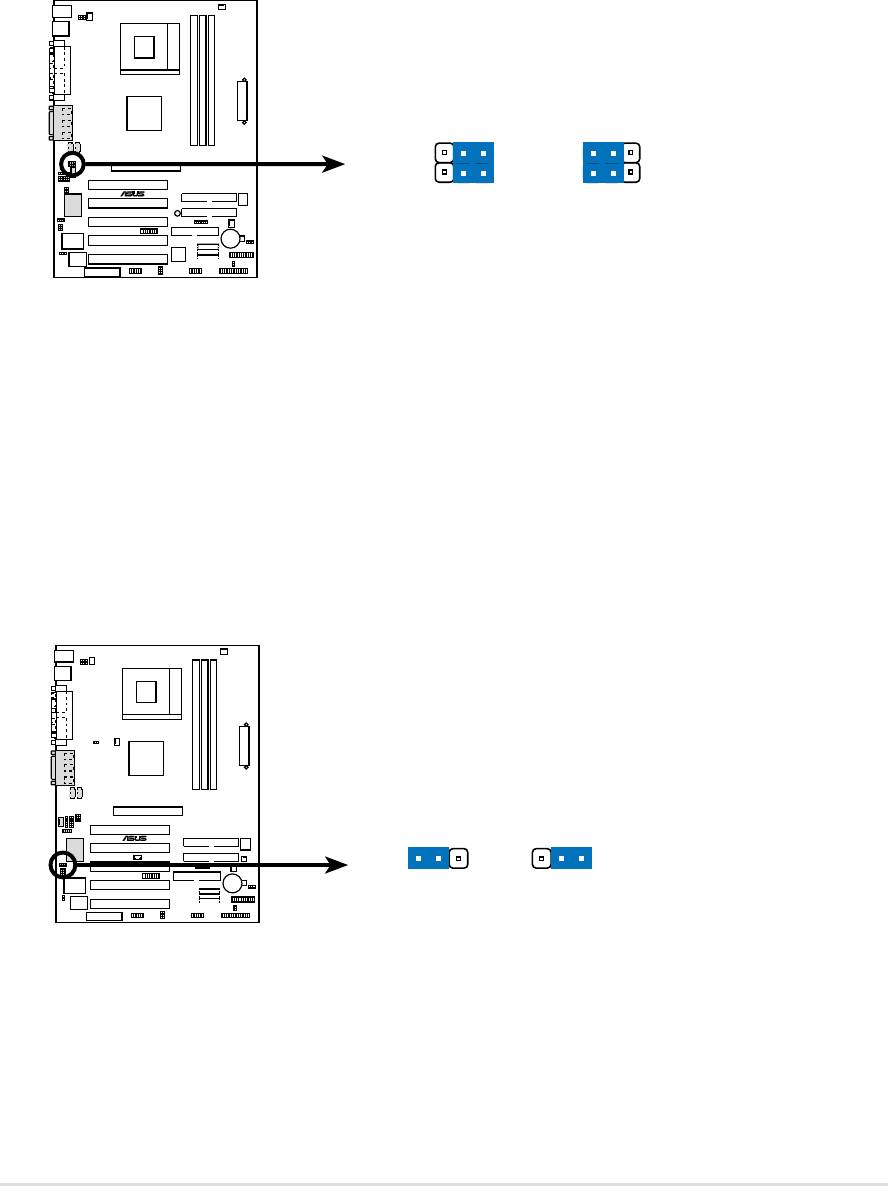
5) Bass Center Setting (Two x 3 pin CENTER/BASS, BASS/CENTER)
(audio models only)
Use these jumpers in conjunction with the C-Media PCI Audio Driver and to
adjust output for 4 or 6 speaker audio. No audio standard exists for the three
pick-up surfaces on male audio jacks, therefore it may be necessary to switch
jumpers from the default position, [1-2], to [2-3], in order to reroute signals
among the internal leads in the Line-In, Line-Out, Mic female sockets.
1223
BCS1
BCS1
BCS2
BCS2
A7S333
®
(CENTER/BASS)(BASS/CENTER)
(Default)
A7S333 Bass Center Setting
6) Audio Setting (3 pin Audio_En)
The onboard 6 channel audio chip may be enabled or disabled using these
jumpers. The default, [2-3], enables the audio setting. Disable the onboard
audio system if using a PCI audio card on any of the expansion slots.
AUDIO_EN
A7S333
®
12
23
Disable
Enable
(Default)
A7S333 Audio Codec Setting
ASUS A7S333 motherboard user guide
25
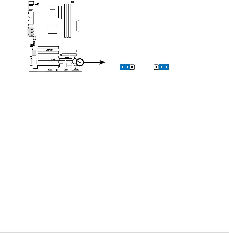
7) Clear RTC RAM (CLRTC)
This jumper allows you to clear the Real Time Clock (RTC) RAM in CMOS.
You can clear the CMOS memory of date, time, and system setup parameters
by erasing the CMOS RTC RAM data. The RAM data in CMOS is powered
by the onboard button cell battery.
To erase the RTC RAM:
1. Turn OFF the computer and unplug the power cord.
2. Remove the battery.
3. Remove the jumper cap from the Normal position and place it on
the [1-2], Clear CMOS position. After 5 seconds, replace the
jumper cap to the Normal position.
4. Re-install the battery.
5. Plug the power cord and turn ON the computer.
6. Hold down the <Del> key during the boot process and enter BIOS
setup to re-enter data.
A7S333
®
CLRTC
12
23
NormalClear CMOS
A7S333 Clear RTC RAM
(Default)
26
Chapter 2: Hardware information
2.8 Connectors
This section describes and illustrates the internal connectors on the
motherboard.
WARNING! Some pins are used for connectors or power sources. These
are clearly distinguished from jumpers in the Motherboard Layout. Placing
jumper caps over these connector pins will cause damage to your
motherboard.
IMPORTANT! Ribbon cables should always be connected with the red
stripe to Pin 1 in the connector scoket.
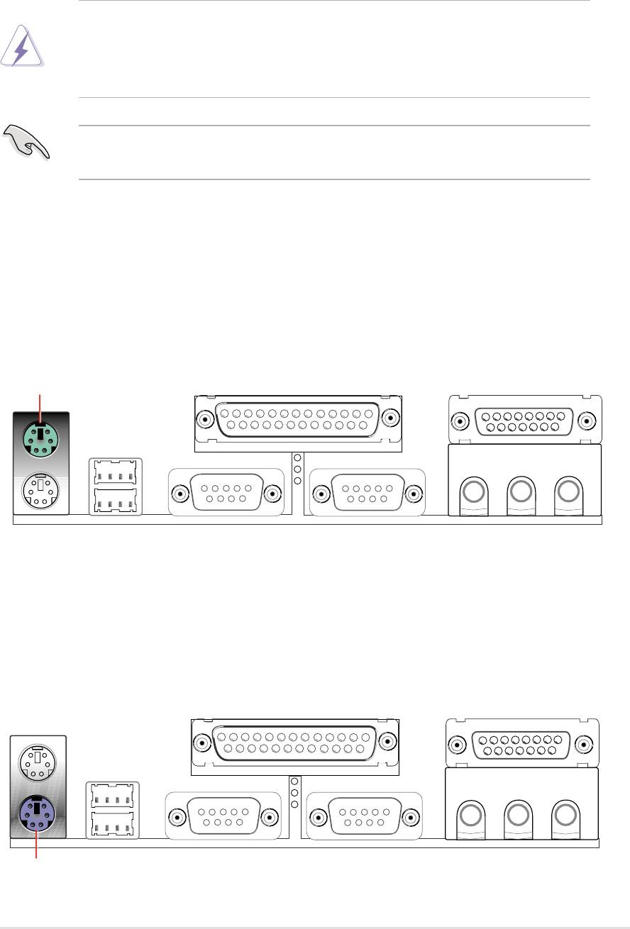
1) PS/2 Mouse Port (Green 6-pin PS2KBMS)
The system automatically directs IRQ12 to the PS/2 mouse if one is detected.
If no mouse is detected, IRQ12 become available to expansion cards. See
PS/2 Mouse Function Control in 4.4 Advanced Menu.
PS/2 Mouse (6-pin Female)
2) PS/2 Keyboard Port (Purple 6-pin PS2KBMS)
This connection is for a standard keyboard using an PS/2 plug (mini DIN).
This connector does not allow standard AT size (large DIN) keyboard plugs.
You may use a DIN to mini DIN adapter on standard AT keyboards.
PS/2 Keyboard (6-pin Female)
ASUS A7S333 motherboard user guide
27
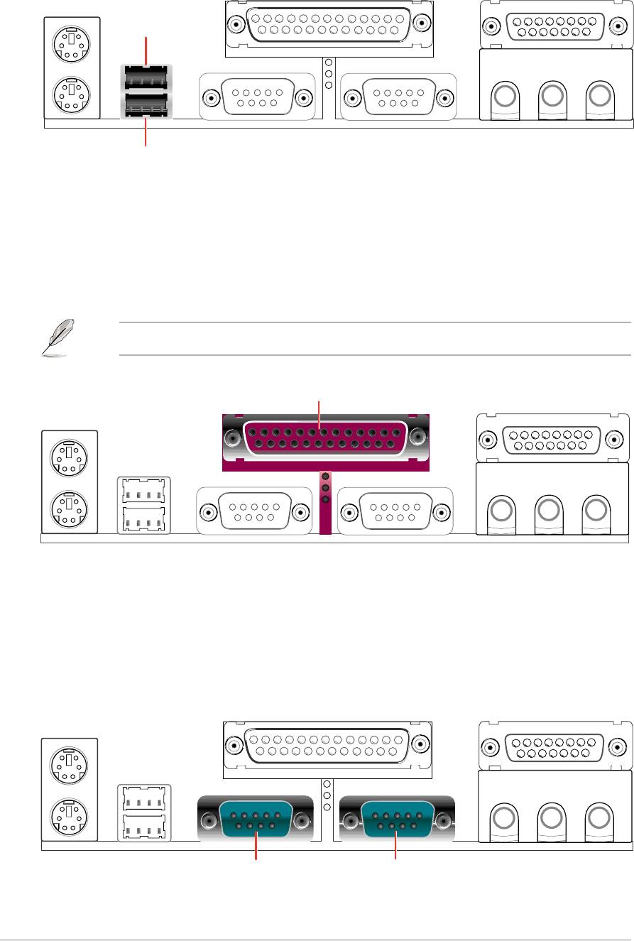
3) Universal Serial Bus Ports 1 and 2 (Black two x 4-pin USB)
Two USB ports are available for connecting USB devices.
USB 1
Universal Serial Bus (USB) 2
4) Parallel Port (Burgundy 25-pin LPT)
You can enable the parallel port and choose the IRQ through Onboard
Parallel Port (see 4.4.2 I/O Device Configuration).
NOTE! Serial printers must be connected to the serial port.
Parallel Port (25-pin Female)
5) Serial Ports (Teal/Turquoise two x 9-pin COM1 / COM2)
Two serial ports can be used for pointing devices or other serial devices. To
enable these ports, see Onboard Serial Port 1 / Onboard Serial Port 2 in
4.4.2 I/O Device Configuration for the settings.
COM2COM1
Serial Ports (9-pin Male)
28
Chapter 2: Hardware information
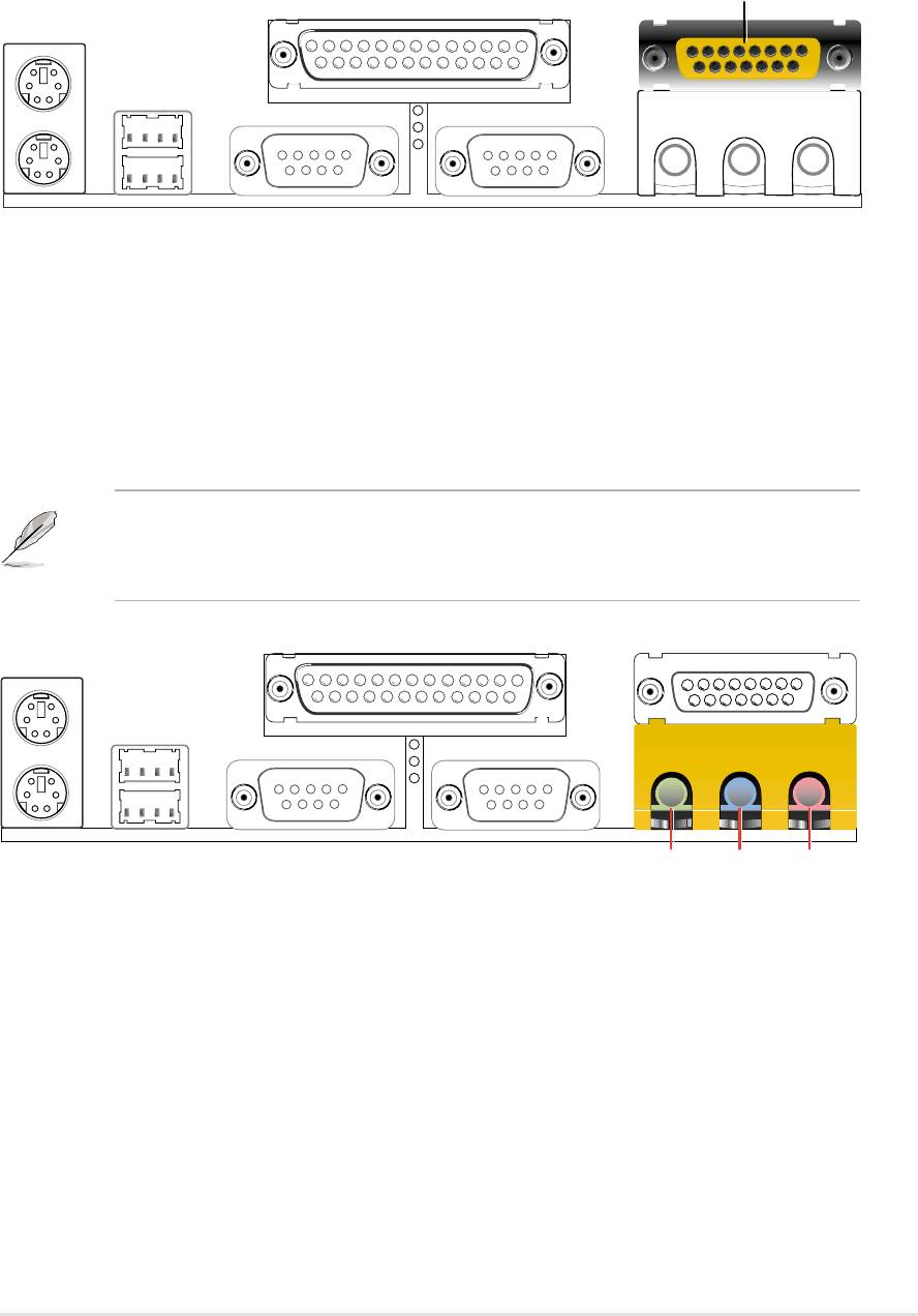
6) Game/MIDI Ports (Gold 15-pin GAME_AUDIO) (audio model only)
This connector supports a joystick or a game pad for playing games, and
MIDI devices for playing or editing audio files.
Game/MIDI (15-pin Female)
7) Audio Connectors (Three 1/8” AUDIO) (audio model only)
The Line Out (lime) connects a headphone or speakers. The Line In (light
blue) connects a tape players or other audio sources. The Mic (pink) connects
a microphone.
NOTE! The functions of the audio connectors Line Out, Line In, and Mic
change when the 6-channel audio feature is enabled. Refer to Chapter
5. SOFTWARE SETUP.
MicLine InLine Out
1/8" Stereo Audio Connectors
ASUS A7S333 motherboard user guide
29
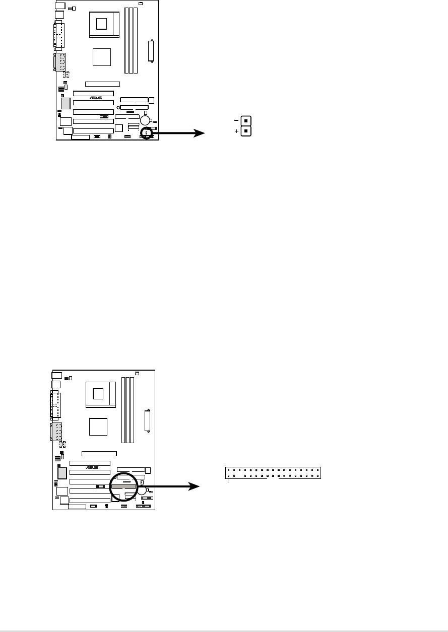
8) IDE Activity LED (2-pin IDE_LED)
This connector supplies power to the cabinet’s IDE activity LED. Read and
write activity by devices connected to the Primary or Secondary IDE
connectors cause the IDE LED to light up.
TIP: If the case-mounted LED does not
light, try reversing the 2-pin plug.
A7S333
®
IDE_LED
A7S333 IDE Activity LED
9) Floppy Disk Drive Connector (34-1 pin FLOPPY)
This connector supports the provided floppy drive ribbon cable. After
connecting the single end to the board, connect the two plugs on the other
end to the floppy drives. (Pin 5 is removed to prevent inserting in the
wrong orientation when using ribbon cables with pin 5 plugged).
FLOPPY
NOTE: Orient the red markings on
the floppy ribbon cable to PIN 1.
A7S333
®
PIN 1
A7S333 Floppy Disk Drive Connector
30
Chapter 2: Hardware information
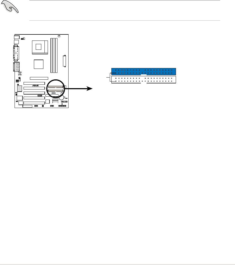
10) Primary (Blue) / Secondary (Black) IDE Connectors
(40-1 pin PRI_IDE and SEC_IDE)
The Primary and Secondary IDE connectors support the IDE hard disk ribbon
cables supplied with the motherboard. Connect the cable’s blue connector
to the motherboard’s primary IDE connector (recommended) or the secondary
IDE connector. Connect the opposite end of the cable to your UltraDMA100/
66 device (hard disk drive). If a second hard disk drive is connected,
youmay reset its jumper to Slave or Master/Slave mode. Non-UltraDMA100/
66 devices should be connected to the secondary IDE connector. BIOS
supports specific device bootup (see 4.6 Boot Menu.) UltraDMA100 is
backward compatible with DMA66/33 and with all with existing DMA devices
and systems.
IMPORTANT! UltraDMA100 IDE devices require a 40-pin 80-conductor
cable.
PRI_IDE Connector
PIN 1
A7S333
®
SEC_IDE Connector
NOTE: Orient the red markings
(usually zigzag) on the IDE
ribbon cable to PIN 1.
A7S333 IDE Connectors
ASUS A7S333 motherboard user guide
31
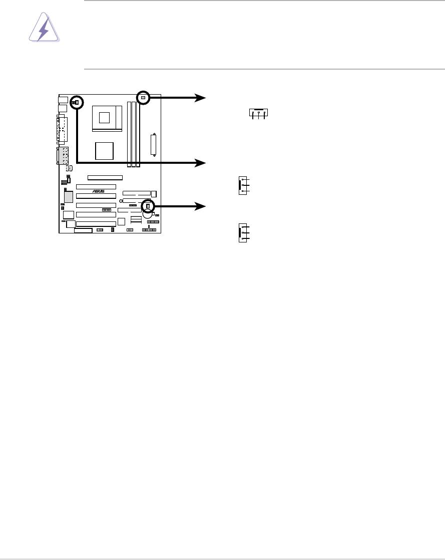
11) CPU Fan, Power Fan, and Chassis Fan Connectors
(CPU_, PWR_, CHA_FAN)
Three fan connectors support cooling fans of 350mA (4.2 Watts) or less.
Orient the fans so that airflow flows across the onboard heat sinks instead of
expansion slots. The fan wiring and plug vary depending on the type
employed. Connect the fan cable to the connector, ensuring that the black
wire matches the ground pin. (Use the “Rotation” signal only with a specially
designed fan with a rotation signal. You can monitor the Rotations Per Minute
(RPM) using ASUS PC Probe (see 5. Software Support).
WARNING! Make sure to connect the fan cables to the fan connectors.
Lack of sufficient airflow within the system could cause damage to the
motherboard. These are not jumpers, do not place jumper caps over
these connectors!
PWR_FAN
+12V
GND
Rotation
CPU_FAN
GND
A7S333
®
+12V
Rotation
CHA_FAN
GND
+12V
Rotation
A7S333 12-Volt Fan Connectors
32
Chapter 2: Hardware information
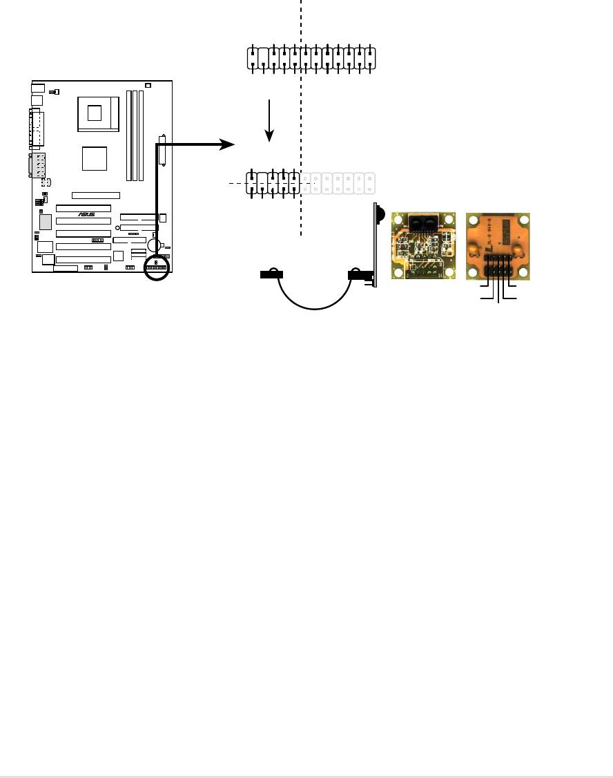
12) ASUS iPanel / Infrared Connector (24-1 pin AFPANEL)
This connector supports an optional ASUS iPanel, an easy to access drive
bay with front I/O ports, status LEDs, and space reserved for a hard disk
drive. Alternatively, if not using an ASUS iPanel, connect an optional wireless
transmitting and receiving infrared module to the SIR connector for wireless
transmitting/remote control functions through an external infrared module.
AFPANEL
+5 V
IRRX
GND
IRTX
SMBDATA
+3VSB
NC
NC
NC
NC
NC
NC
+5V SMBCLK
NC
GND
BATT
CIRRX
+5VSB
MLED-
EXTSMI#
PCIRST#
CHASSIS#
+5 V
IRRX
GND
IRTX
SIR
Standard Infrared (SIR)
CIR
Front View Back View
®
NC
NC
A7S333
GND
CIRRX
+5VSB
IR_CON
IRTX
+5V
A7S333 iPanel Connector
GND
(NC)
IRRX
ASUS A7S333 motherboard user guide
33
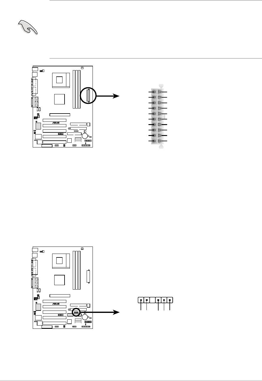
13) Power Supply Connectors (20-pin block ATXPWR)
This connector supports an ATX 12V power supply. The plug from the power
supply fits in only one orientation. Push down firmly ensuring that the pins
are aligned.
IMPORTANT! Make sure that the ATX 12V power supply (minimum
recommended wattage: 230W) can supply at least 10mA on the +5-volt
standby lead (+5VSB). The system may become unstable and may
experience difficulty powering up if the power supply is inadequate. For
Wake-On-LAN support, the ATX power supply must supply at least 720mA
+5VSB.
ATXPWR
+12.0VDC
+5.0VDC
+5VSB
+5.0VDC
PWR_OK
-5.0VDC
GND
GND
+5.0VDC
GND
GND
GND
A7S333
®
+5.0VDC
PS_ON#
GND
GND
+3.3VDC
-12.0VDC
+3.3VDC
+3.3VDC
A7S333 ATX Power Connectors
14) SMBus Connector (6-1 pin SMB)
This connector supports SMBus (System Management Bus) devices. SMBus
devices communicate by means of the SMBus with an SMBus host and/or
other SMBus devices. SMBus is a multi-device bus that permits multiple
chips to connect to the same bus and enable each one to act as a master by
initiating data transfer.
SMB_CON
A7S333
®
1
+3V
Ground
SMBCLK
FLOATING
SMBDATA
A7S333 SMBus Connector
34
Chapter 2: Hardware information
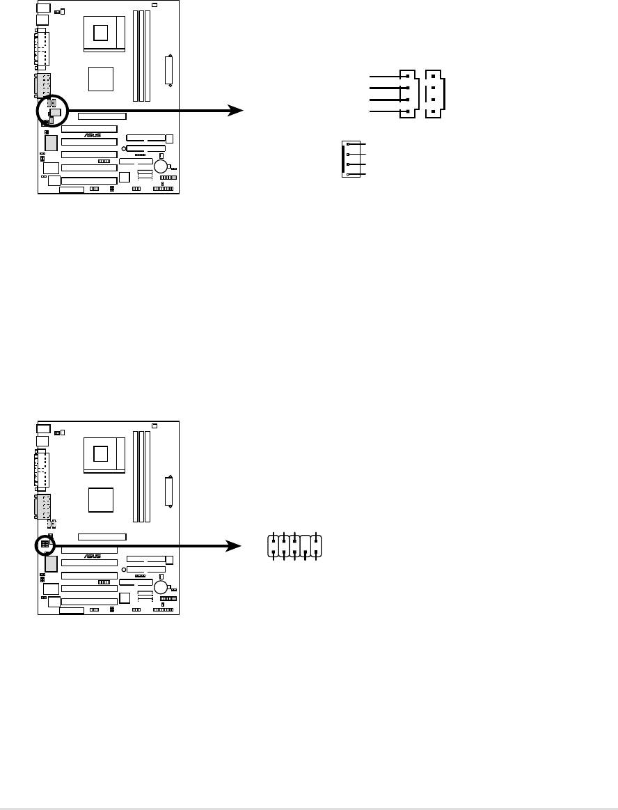
15) Internal Audio Connectors (Three x 4-1 pin CD, AUX, MODEM)
(on audio models only)
These connectors allow you to receive stereo audio input from sound sources
as a CD-ROM, TV tuner, or MPEG card. The MODEM connector allows the
onboard audio to interface with a voice modem card with a similar connector.
It also allows the sharing of mono_in (such as a phone) and a mono_out
(such as a speaker) between the audio and a voice modem card.
CD(Black)AUX (White)
Right Audio Channel
Ground
Ground
Left Audio Channel
A7S333
®
MODEM
Modem-Out
Ground
Ground
Modem-In
A7S333 Internal Audio Connectors
16) Front Panel Audio Connector (10-1 pin FP_AUDIO)
(on audio models only)
This connector supports audio control to the front panel.
FP_AUDIO
AGND
BLINE_OUT_R
BLINE_OUT_L
A7S333
®
NC
MIC2
MICPWR +5VA
Line out_R
Line out_L
A7S333 Front Panel Audio Connector
ASUS A7S333 motherboard user guide
35
17) Smart Card Reader Connector (14-1 pin SMARTCON)
This connector accommodates a Smart Card Reader that allows you to
conveniently make transactions such as financial, health care, telephony, or
traveling services through a Smart Card user interface software. When using
this connector, configure the UART2 Use As parameter in BIOS to set UART2
for use with Smart Card. See section “4.4.2 I/O Device Configuration” for
details.
SMARTCON
A7S333
®
NC
NC
SCRREST
NC
SCRUI
SCRRES#
1
NC
NC
VCC
GND
NC2
A7S333 Smartcard
SCRCLK
SCRFET#
18) IEEE-1394 Header (Three x 8-pin IEEE1394_1,2,3) (Optional)
This header supports an IEEE-1394 serial connector cable set that mounts
to a standard expansion slot in the computer case. 1394-compliant internal
fixed disk drives may also be connected to these headers.
IEEE-1394_1
IEEE-1394_2
IEEE-1394_3
A7S333
®
+12V
+12V
+12V
TPA2-
TPB2-
TPA2-
TPB2-
TPA2-
TPB2-
Ground
Ground
TPA2+
TPB2+
Ground
Ground
Ground
TPA2+
TPB2+
Ground
Ground
Ground
TPA2+
TPB2+
Ground
A7S333 IEEE-1394 Headers
36
Chapter 2: Hardware information
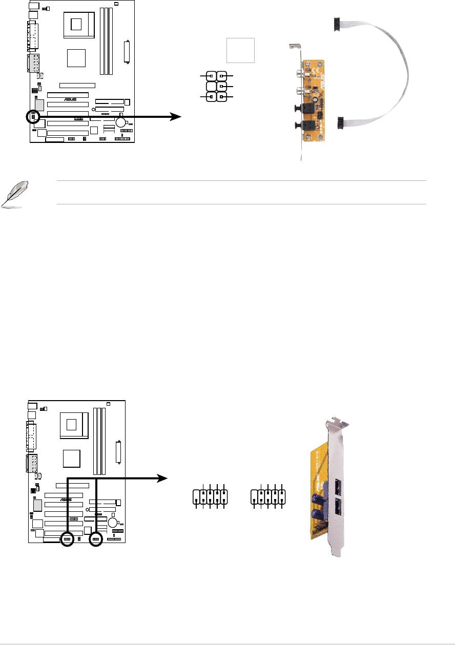
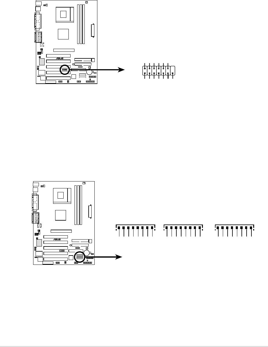
19) Digital Audio Interfaces (6-1pin SPDIF) (Optional)
This connector supports an S/PDIF audio module that permits digital instead
of analog sound output. Connect one end of the audio cable to the S/PDIF
Out connector on the motherboard, and the other end to the S/PDIF module.
SPDIF_C
GND
SPDIF_OUT
+5V
A7S333
®
GND
SPDIF_IN
1
A7S333 Digital Audio Connector
The SPDIF module is not included in the motherboard package.
20) USB Headers (Two x 10-1 pin USB_34, USB_56)
If the USB port connectors on the back panel are inadequate, two USB
headers are available for four additional USB port connectors. Connect a 2-
port USB connector set to a USB header and mount the USB bracket to an
open slot in the chassis. (The USB connector set is optional and does not
come with the motherboard package.)
USB_34USB_56
GND
USBP5+
USBP5–
USB Power
GND
USBP3+
USBP3–
USB Power
610
610
A7S333
®
15
15
NC
NC
GND
GND
USBP4+
USBP4–
USBP2+
USBP2–
USB Power
USB Power
A7S333 Front Panel USB Headers
ASUS A7S333 motherboard user guide
37
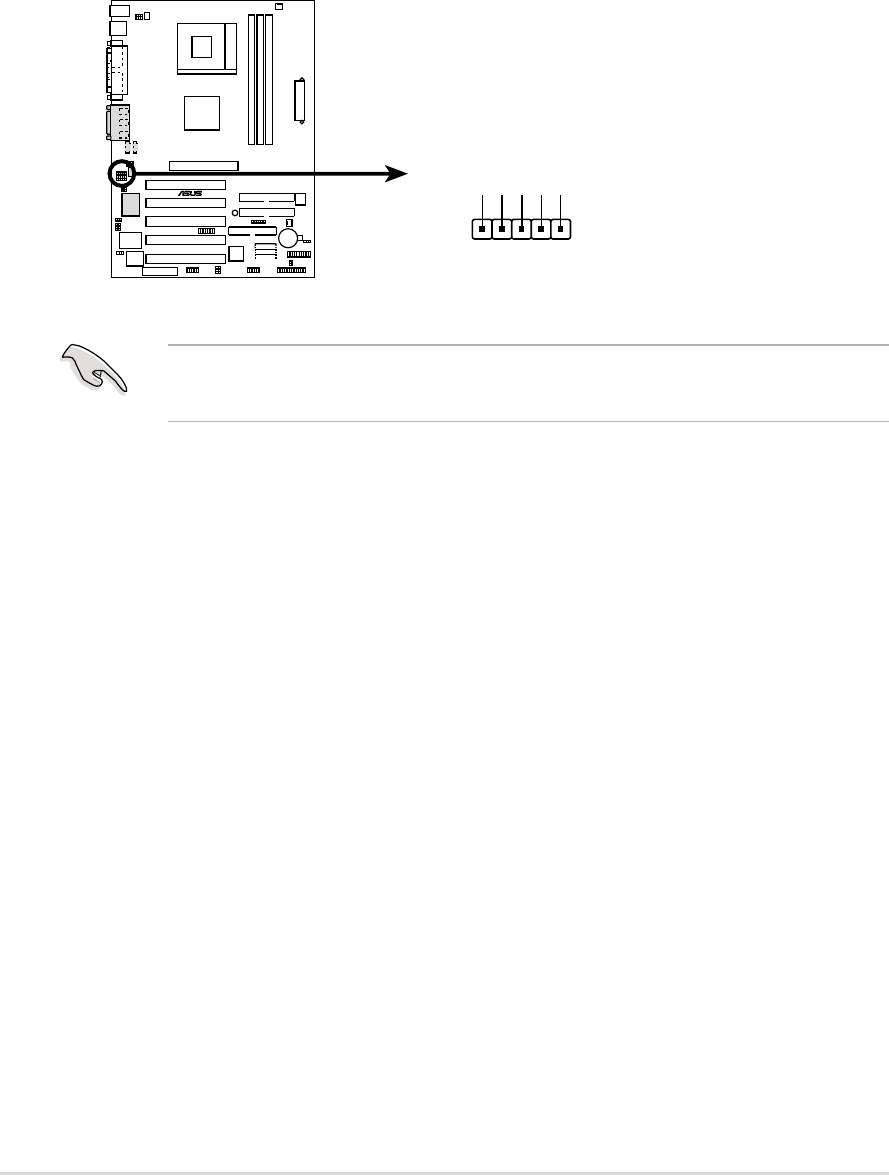
21) Line-in Connecters (5 pin FP_LIne_In) (Optional)
By default, these jumpers are shorted (jumpers on) to route the signal from
the audio controller to the rear panel Line Out jack to make it available for
audio out devices such as speakers or a headphone. If you connect the Intel
Front Panel audio cable to the FP_AUDIO connector, (see page 35), then
remove the caps from these two jumpers to permit automatic switching of
audio signals between the rear panel Line Out jack and the Intel audio cable.
FP_LINE_IN
A7S333
®
BLINE_IN_R
LINE_IN_R
AGND
BLINE_LIN_L
ALINE_LIN_L
A7S333 LINE_IN Connector
IMPORTANT! The motherboard ships with Jumper caps over pins 1-2
and 4-5. Remove them only when making audio input connections.
38
Chapter 2: Hardware information
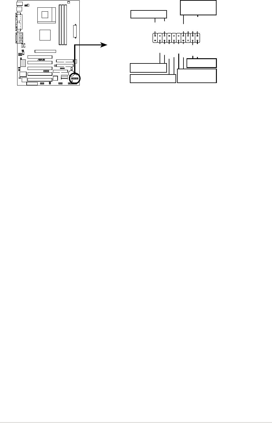
The following 20-pin PANEL illustration is for items 22-27:
Speaker
Connector
Power LED
+5 V
PLED
+5V
Ground
Ground
Speaker
+5 V
MLED
PWR
Ground
Ground
Reset
ExtSMI#
Ground
A7S333
®
Reset SW
Message LED
ATX Power
SMI Lead
Switch*
*
Requires an ATX power supply.
A7S333 System Panel Connectors
22) System Power LED Lead (3-1 pin PLED)
This 3-1 pin connector supplies the system power LED. The LED lights up
when the system power is on, and the LED blinks when the system is in
sleep or soft-off mode.
23) System Warning Speaker Lead (4 pin SPEAKER)
This 4-pin connector supplies the case-mounted speaker to sound system
beeps and warnings.
24) System Message LED Lead (2 pin MLED)
This 2-pin connector supports the system message LED to indicate receipt
of messages from a fax/modem. The normal status for this LED is ON,
when there is no incoming data signal. The LED blinks when data is received.
The system message LED feature requires an ACPI OS and driver support.
25) System Management Interrupt Lead (2 pin SMI)
This 2-pin connector permits switching to suspend mode, or “Green” mode,
in which system activity is instantly decreased to save power and to expand
the life of certain system components. Attach the case-mounted suspend
switch this 2-pin connector.
26) ATX Power Switch / Soft-Off Switch Lead (2 pin PWR)
The system power is controlled by a momentary switch attached to this
connector. Pressing the button switches the system between ON and SLEEP,
or ON and SOFT OFF, depending on the BIOS or OS settings. Pressing the
button while in the ON mode for more than 4 seconds turns the system off.
27) Reset Switch Lead (2-pin RESET)
This 2-pin connector supports the case-mounted reset switch for rebooting
the system without turning off the power switch.
ASUS A7S333 motherboard user guide
39

40
Chapter 2: Hardware information
