Dell Precision 350 – страница 2
Инструкция к Компьютеру Dell Precision 350
Оглавление

Back to Contents Page
Closing the Computer Cover
DellPrecision™Workstation350ServiceManual
1. Ensure that all cables are connected, and fold cables out of the way.
Gently pull the power cables toward you so that they do not get caught underneath the drives.
2. Ensure that no tools or extra parts are left inside the computer.
3. Close the computer cover:
a. Pivot the cover down.
b. Press down on the right side of the cover until it closes.
c. Press down on the left side of the cover until it closes.
d. Ensure that both sides of the cover are locked. If not, repeat step 3.
4. Connect your computer and devices to electrical outlets, and turn them on.
Back to Contents Page
NOTICE: To connect a network cable, first plug the cable into the network wall jack and then plug it into the computer.
Back to Contents Page
Opening the Computer Cover
DellPrecision™Workstation350ServiceManual
1. Shut down the computer through the Start menu.
2. Ensure that your computer and attached devices are turned off. If your computer and attached devices did not automatically turn off when you shut
down your computer, turn them off now.
3. Disconnect any telephone or telecommunication lines from the computer.
4. Disconnect your computer and all attached devices from electrical outlets, and then press the power button to ground the system board.
5. If you have installed a padlock through the padlock ring on the back panel, remove the padlock.
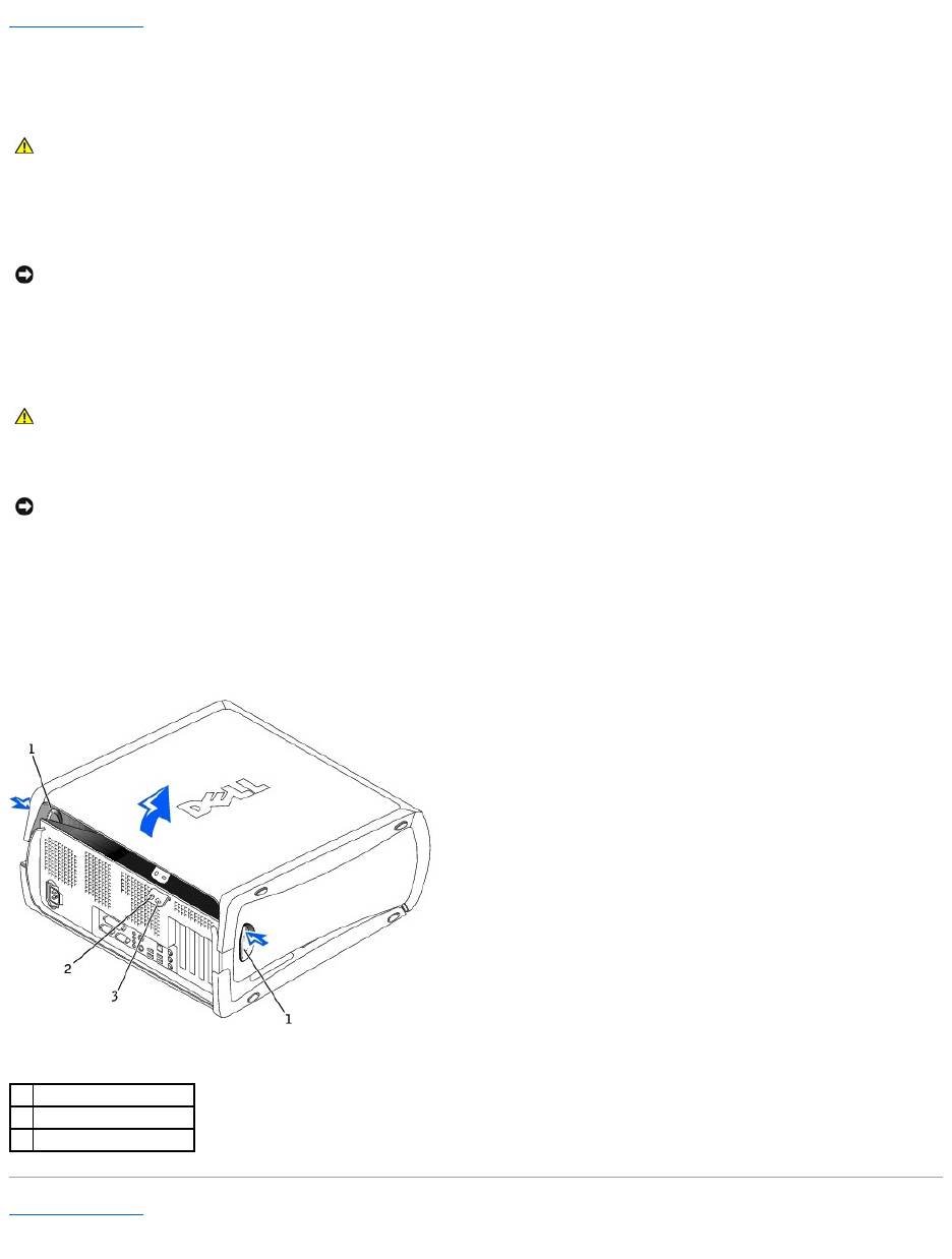
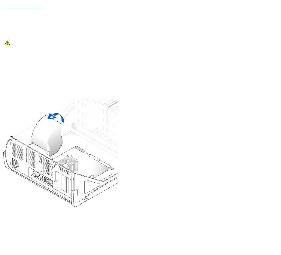
6. Lay the computer on its side as shown in the following illustration.
7. Open the cover:
a. Facing the back of the computer, press the release button on the right side of the computer with one hand while pulling up on the top of the
cover with the other hand.
b. Press the release button on the left side of the computer with one hand while pulling up on the top of the cover with the other hand.
c. Hold the bottom of the computer with one hand, and then pull open the cover with the other hand.
Back to Contents Page
CAUTION: Before you begin any of the procedures in this section, follow the safety instructions in the System Information Guide.
NOTICE: To disconnect a network cable, first unplug the cable from your computer and then unplug it from the network wall jack.
CAUTION: To guard against electrical shock, always unplug your computer from the electrical outlet before opening the cover.
NOTICE: Ensure that sufficient space exists to support the open cover—at least 30 cm (1 ft) of desk top space.
1
release buttons (2)
2
padlock ring
3
security cable slot
Back to Contents Page
Drives
DellPrecision™Workstation350ServiceManual
Overview
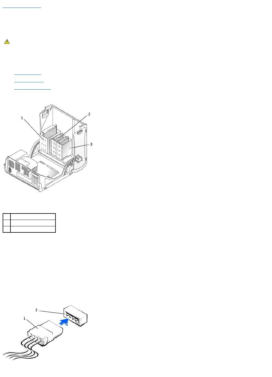
Your computer supports:
l Two hard drives
l Two floppy drives
l Two CD or DVD drives
IDE Drive Addressing
When you connect two IDE devices to a single IDE interface cable and configure them for the cable select setting, the device attached to the last connector on
the interface cable is the master or boot device (drive 0), and the device attached to the middle connector on the interface cable is the slave device (drive 1).
See the drive documentation in your upgrade kit for information on configuring devices for the cable select setting.
Your computer supports up to two IDE devices. Hard drives should be connected to the connector labeled "PRI IDE," and CD/DVD drives should be connected
to the connector labeled "SEC IDE."
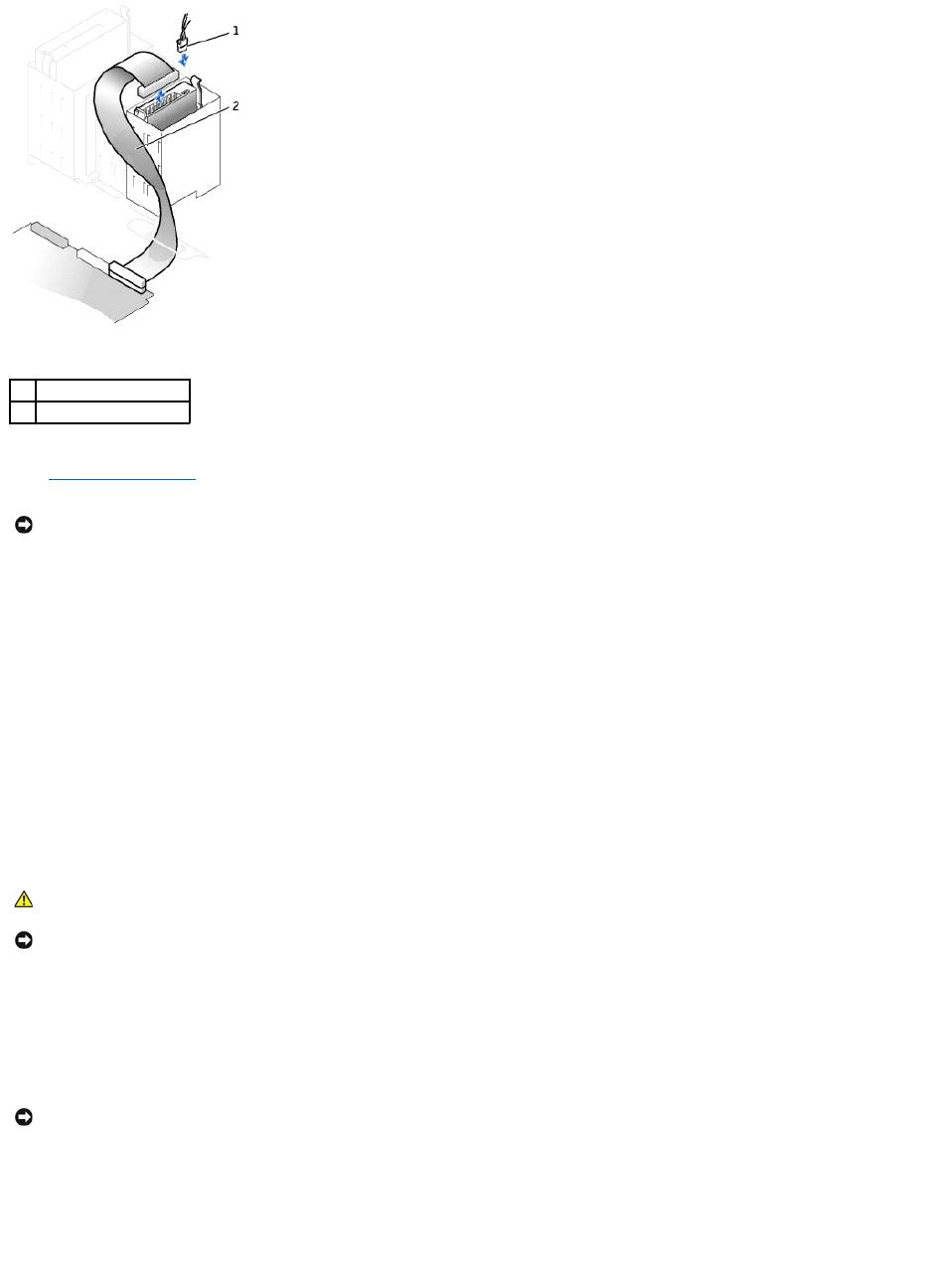
Connecting Drive Cables
When you install a drive, you connect two cables—a DC power cable and an interface cable—to the back of the drive.
CAUTION: Before you begin any of the procedures in this section, follow the safety instructions in the System Information Guide.
1
CD/DVD drive(s)
2
floppy drive(s)
3
hard drive(s)
Most interface connectors are keyed for correct insertion; that is, a notch or a missing pin on one connector matches a tab or a filled-in hole on the other
connector. Keyed connectors ensure that the pin-1 wire in the cable (indicated by the colored stripe along one edge of the cable) goes to the pin-1 end of the
connector. The pin-1 end of a connector on a board or a card is usually indicated by a silk-screened "1" printed directly on the board or card.
Removing a Hard Drive
1. If you are replacing a hard drive that contains data you want to keep, back up your files before you begin this procedure.
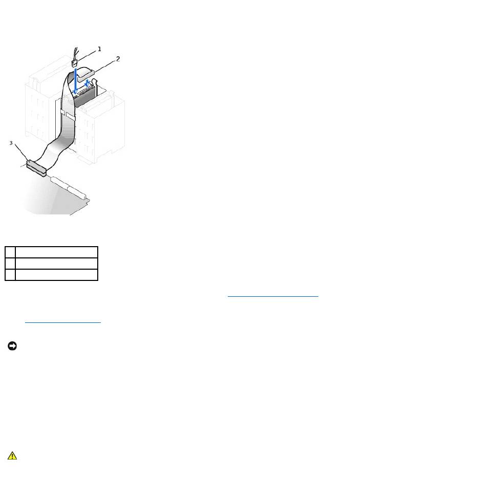
2. Disconnect the power and hard-drive cables from the drive.
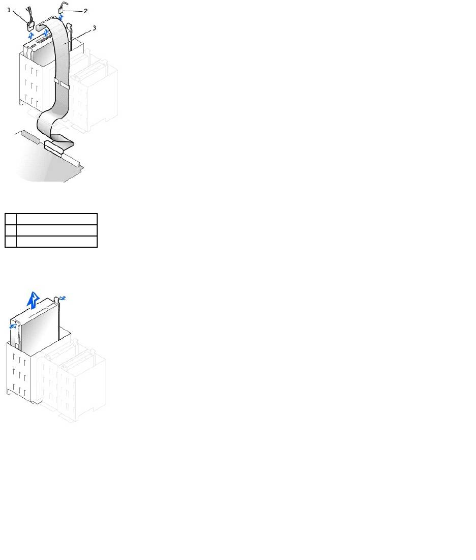
3. Press in on the tabs on each side of the drive and slide the drive up and out.
1
power cable
2
power input connector
1
interface connector
2
colored stripe on edge of
interface cable
3
interface cable
NOTICE: When you connect an interface cable, do not place the colored stripe away from pin 1 of the connector. Reversing the cable prevents the drive
from operating and could damage the controller, the drive, or both.
CAUTION: Before you begin any of the procedures in this section, follow the safety instructions in the System Information Guide.
NOTICE: To avoid damage to the drive, do not set it on a hard surface. Instead, set the drive on a surface, such as a foam pad, that will sufficiently
cushion it.
1
power cable
2
hard-drive cable
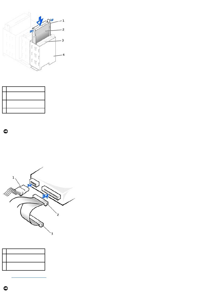
Installing a Hard Drive
1. Unpack the replacement hard drive, and prepare it for installation.
2. Check the documentation for the drive to verify that it is configured for your computer.
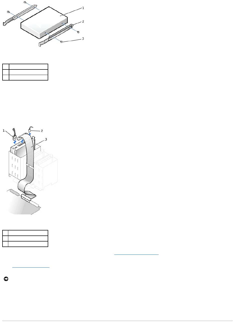
3. If your replacement hard drive does not have the bracket rails attached, remove the rails from the old drive by removing the two screws that secure
each rail to the drive. Attach the bracket rails to the new drive by aligning the screw holes on the drive with the screw holes on the bracket rails and
then inserting and tightening all four screws (two screws on each rail).
4. Gently slide the drive into place until the tabs securely click into position.
5. Connect the power and hard-drive cables to the drive.
1
tabs (2)
2
hard drive
1
drive
2
bracket rails (2)
3
screws (4)
NOTICE: Match the colored strip on the cable with pin 1 on the drive (pin 1 is marked as "1").
6. Check all connectors to be certain that they are properly cabled and firmly seated.
7. Close the computer cover.
8. Connect your computer and devices to electrical outlets, and turn them on.
See the documentation that came with the drive for instructions on installing any software required for drive operation.
9. If the drive you just installed is the primary drive, insert a bootable floppy disk into drive A.
10. Turn on the computer.
11. Enter system setup, and update the appropriate Primary Drive option (0 or 1).
12. Exit system setup, and restart the computer.
13. Partition and logically format your drive before you proceed to the next step.
See the documentation for your operating system for instructions.
14. Test the hard drive by running the Dell Diagnostics.
15. If the drive you just installed is the primary drive, install your operating system on the hard drive.
Adding a Second Hard Drive
1. Check the documentation for the drive to verify that it is configured for your computer.
2. Remove the two green plastic rails from the inside of the hard-drive bay by gently pulling the rails up and out of the bay.
3. Attach the rails to the hard drive using the two screws attached to the rails.
Ensure that the rail tabs are positioned at the back of the hard drive.
4. Remove the first hard drive from the upper bay and install it in the lower bay:
a. Disconnect the power and the hard-drive cables from the back of the first hard drive.
b. Press in the two green rail tabs and pull the first hard drive out of the upper bay.
c. Gently slide the first hard drive into the lower bay until you hear a click.
d. Reconnect the power and hard-drive cables to the back of the first hard drive.
5. Gently slide the new hard drive into the upper bay until you hear a click.
1
power cable
2
hard-drive cable
NOTICE: To connect a network cable, first plug the cable into the network wall jack and then plug it into the computer.
CAUTION: Before you begin any of the procedures in this section, follow the safety instructions in the System Information Guide.
NOTICE: To avoid damage to the drive, do not set it on a hard surface. Instead, set the drive on a surface, such as a foam pad, that will sufficiently
cushion it.
NOTICE: Do not install any drive into the lower hard-drive bay until you have removed the green drive rails from the inside of the hard-drive bay.
6. Connect a power cable to the drive.
7. Locate the extra connector on the drive cable that is attached to your first hard drive and attach the connector to the second hard drive.
Your computer uses cable-select drive cables. This means that the device connected to the end connector of the drive cable is the master device and
the device connected to the middle connector is the slave device. Be sure that the jumper setting on the new device is set for "cable select" (see the
documentation that came with the drive for information).
8. Close the computer cover.
9. Connect your computer and devices to electrical outlets, and turn them on.
10. See the documentation that came with the drive for instructions on installing any software required for drive operation.
1
rail tabs (2)
2
second hard drive in upper
bay
3
first hard drive in lower
bay
4
hard drive bay
NOTICE: Match the colored strip on the cable with pin 1 on the drive.
1
power cable
2
second hard-drive cable
(secondary drive)
3
first hard-drive cable
(primary boot drive)
NOTICE: To connect a network cable, first plug the cable into the network wall jack and then plug it into the computer.
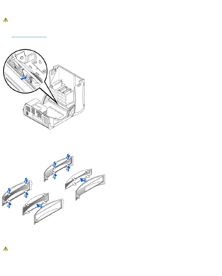
Front-Panel Inserts
If you are installing a new floppy or CD/DVD drive rather than replacing a drive, remove the front-panel inserts.
1. Open the computer cover to a 90-degree angle and release the insert tabs from inside the computer.
2. Press on the insert until it pops free of the front panel cover.
Removing a Floppy Drive
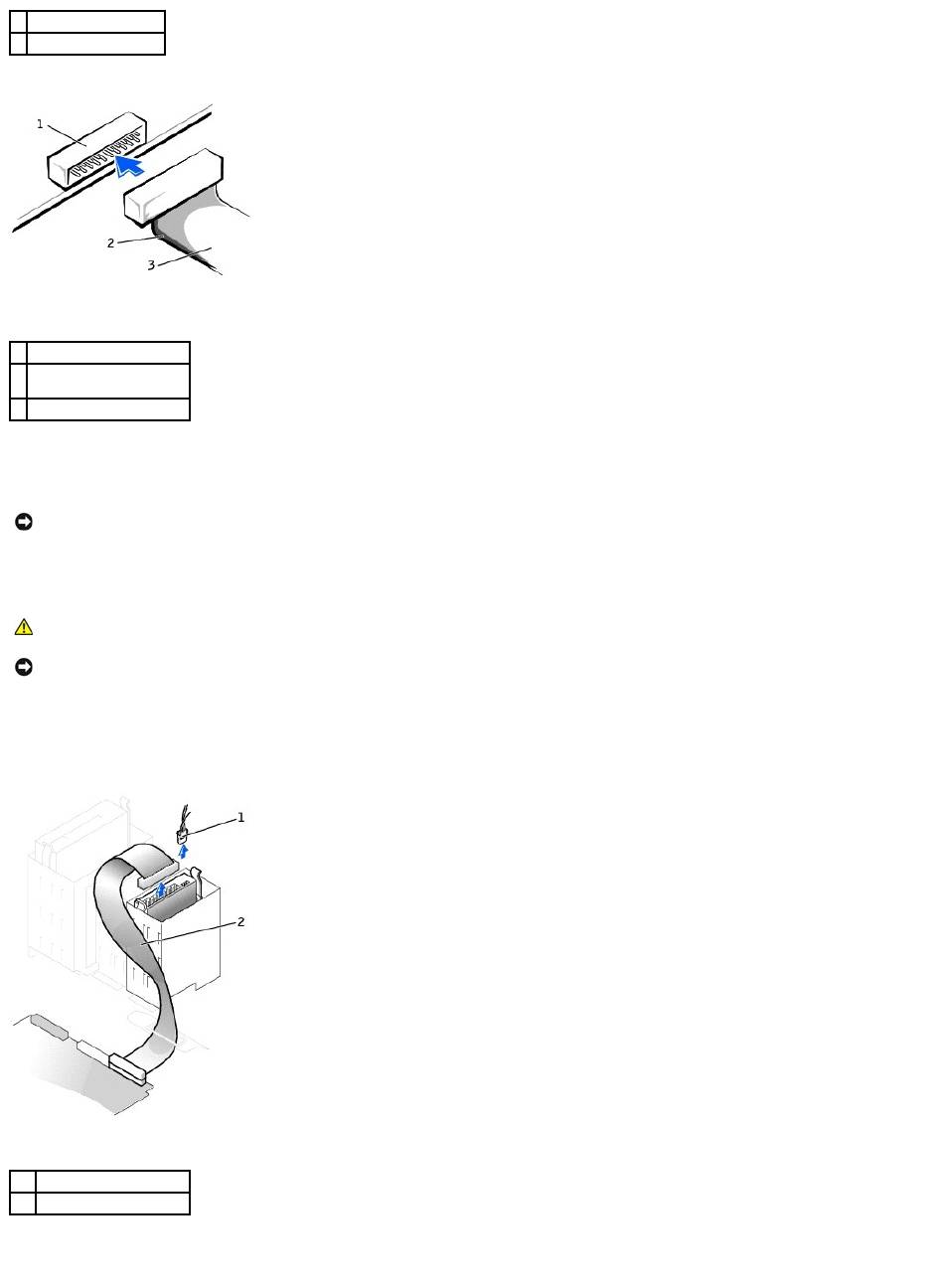
1. Disconnect the power and floppy-drive cables from the back of the floppy drive.
2. Disconnect the other end of the floppy-drive cable from the system board (labeled FLOPPY).
CAUTION: Before you begin any of the procedures in this section, follow the safety instructions in the System Information Guide.
CAUTION: Before you begin any of the procedures in this section, follow the safety instructions in the System Information Guide.
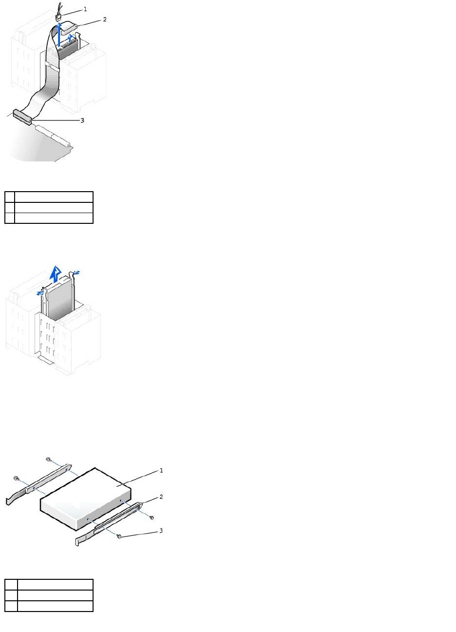
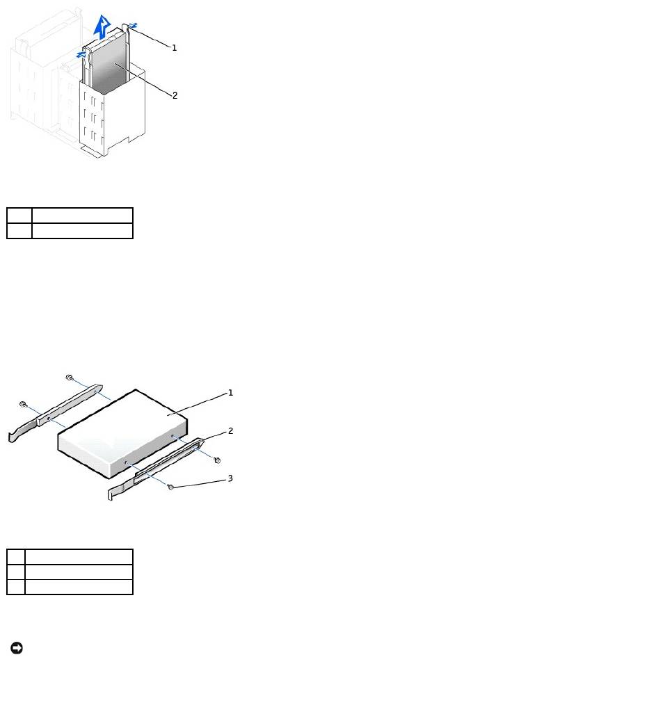
3. Press inward on the two tabs on the sides of the drive, slide the drive upward, and remove it from the floppy-drive bay.
Installing a Floppy Drive
1. If you are replacing a drive and the new drive does not have the bracket rails attached, remove the rails from the old drive by removing the two screws
that secure each rail to the drive. Attach the bracket to the new drive by aligning the screw holes on the drive with the screw holes on the bracket rails
and then inserting and tightening all four screws (two screws on each rail).
2. Gently slide the drive into place until the tabs securely click into position.
1
power cable
2
floppy-drive cable
3
floppy-drive connector
1
drive
2
bracket rails (2)
3
screws (4)
3. Attach the power and floppy-drive cables to the floppy drive.
4. Connect the other end of the floppy-drive cable to the connector labeled "FLOPPY" on the system board.
5. If you are installing a new floppy drive rather than replacing a drive, remove the front-panel inserts.
6. Check all cable connections, and fold cables out of the way to provide airflow for the fan and cooling vents.
7. Close the computer cover.
8. Connect your computer and devices to electrical outlets, and turn them on.
See the documentation that came with the drive for instructions on installing any software required for drive operation.
9. Enter system setup and update the appropriate Diskette Drive A option to reflect the size and capacity of your new floppy drive.
10. Verify that your computer works correctly by running the Dell Diagnostics.
Removing a CD/DVD Drive
1. Disconnect the power, audio, and CD/DVD drive cables from the back of the drive.
1
power cable
2
floppy-drive cable
3
floppy-drive connector
NOTICE: To connect a network cable, first plug the cable into the network wall jack and then plug it into the computer.
CAUTION: Before you begin any of the procedures in this section, follow the safety instructions in the System Information Guide.
2. Press inward on the two tabs on the sides of the drive, and then slide the drive upward and remove it from the drive bay.
Installing a CD/DVD Drive
1. If you are installing a new drive, unpack the drive and prepare it for installation.
Check the documentation that accompanied the drive to verify that the drive is configured for your computer. If you are installing an IDE drive, configure
the drive for the cable select setting.
2. Connect the new drive to the set of rails that are attached to the inside of the cover. If a set of rails is not attached inside the cover, contact Dell.
3. If you are installing a replacement drive and the new drive does not have the bracket rails attached, remove the rails from the old drive by removing
the two screws that secure each rail to the drive. Attach the bracket to the new drive by aligning the screw holes on the drive with the screw holes on
the bracket rails and then inserting and tightening all four screws (two screws on each rail).
1
power cable
2
audio cable
3
CD/DVD drive cable
4. Gently slide the drive into place until the tabs securely click into position.
5. If you are installing a drive that has its own controller card, install the controller card in a card slot.
See the documentation that accompanied the drive and controller card to verify that the configuration is correct for your computer. Change any settings
necessary for correct configuration.
6. Connect the power, audio, and CD/DVD drive cables to the drive.
7. If you are installing a new CD/DVD drive rather than replacing a drive, remove the front-panel inserts.
8. Check all cable connections, and fold cables out of the way to provide airflow for the fan and cooling vents.
9. Close the computer cover.
10. Connect your computer and devices to electrical outlets, and turn them on.
See the documentation that came with the drive for instructions on installing any software required for drive operation.
11. Update your configuration information by setting the appropriate Drive option (0 or 1) under Drives: Secondary to Auto. See "System Setup Options"
in your User's Guide for more information.
12. Verify that your computer works correctly by running the Dell Diagnostics.
1
drive
2
bracket rails (2)
3
screws (4)
1
power cable
2
audio cable
3
CD/DVD drive cable
NOTICE: To connect a network cable, first plug the cable into the network wall jack and then plug it into the computer.

Back to Contents Page
Back to Contents Page
Microprocessor
DellPrecision™Workstation350ServiceManual
Removing the Microprocessor
1. Disconnect the cooling fan power cable from the FAN connector on the system board.
2. Disconnect the power cable from the 12VPOWER connector on the system board.
3. Lift up the airflow shroud.
4. Remove the microprocessor heat sink:
a. For each of the metal securing clips that secure the heat sink to the microprocessor, press down on the clip's latch to release it from the heat-
sink retention base. Then lift the clip away from the heat sink.
b. Lift the heat sink away from the microprocessor.
CAUTION: Before you begin any of the procedures in this section, follow the safety instructions in the System Information Guide.
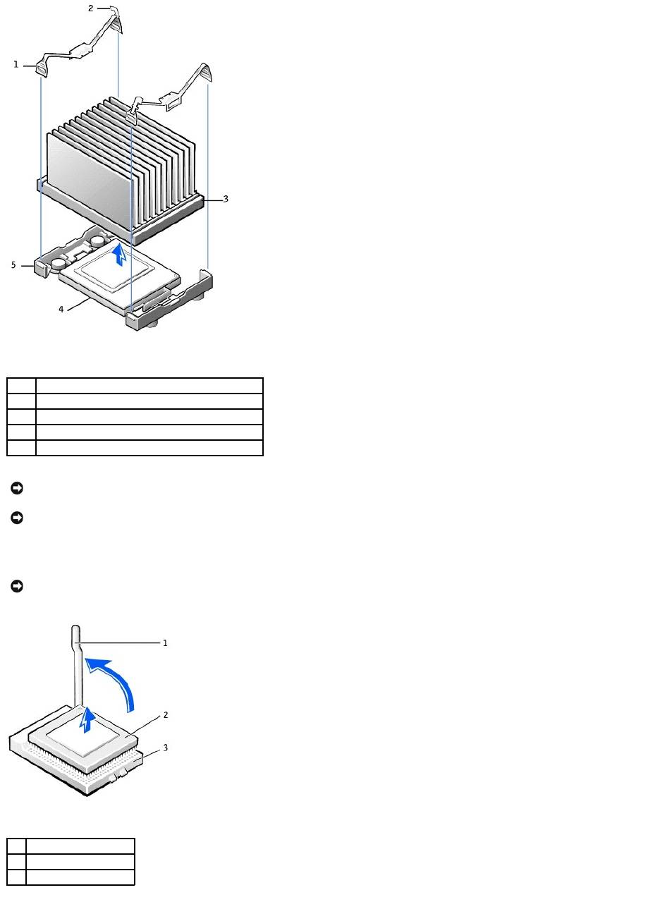
5. Pull the release lever straight up until the microprocessor is released.
6. Remove the microprocessor from the socket.
1
securing clip (2)
2
latch (2)
3
heat sink
4
microprocessor socket
5
retention base
NOTICE: Lay the heat sink down with the thermal grease facing upward.
NOTICE: If you are installing a microprocessor upgrade kit from Dell, discard the original heat sink. If you are not installing a microprocessor upgrade kit
from Dell, reuse the original heat sink and blower when you install your new microprocessor.
NOTICE: Be careful not to bend any of the pins when you remove the microprocessor from the socket. Bending the pins can permanently damage the
microprocessor.
1
release lever
2
microprocessor
3
socket
Leave the release lever extended in the release position so that the socket is ready for the new microprocessor.
Installing the Microprocessor
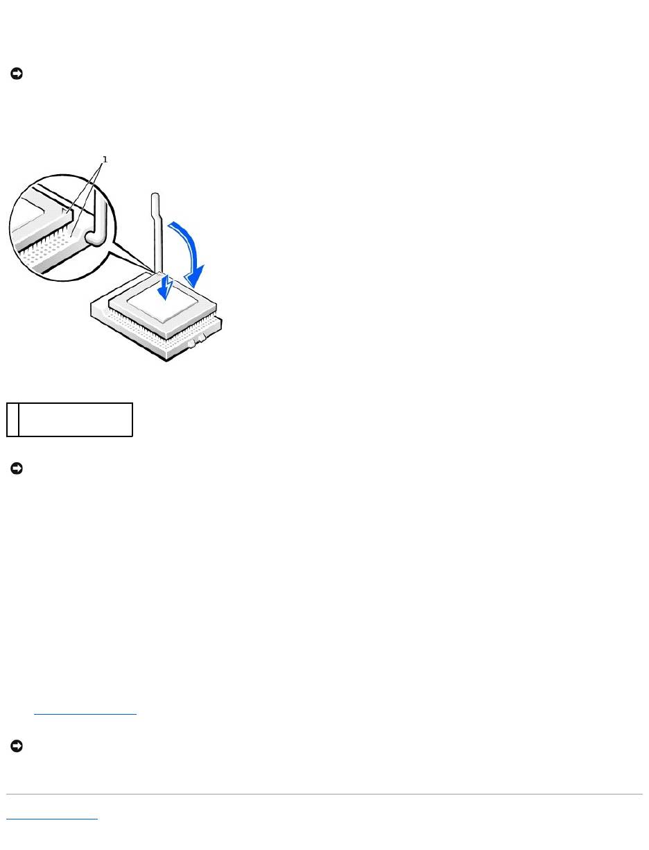
1. If the release lever is not extended to the release position, move it to that position.
2. Align pin-1 (the imprinted corner) of the microprocessor and pin-1 of the socket.
3. Carefully set the microprocessor in the socket and press it down lightly to seat it.
4. Rotate the release lever back toward the system board until it snaps into place, securing the microprocessor.
5. Place the heat sink in the base.
6. To replace the securing clips:
a. Fit the end of the clip that does not have a latch over a tab on the retention base.
b. Fit the middle of the clip over the middle tab on the retention base.
c. Press down the clip's latch so it fits over the tab and secures the clip to the retention base.
7. Lower the airflow shroud over the heat sink.
If you installed a microprocessor replacement kit from Dell, return the original heat sink assembly and microprocessor to Dell in the same package in
which your replacement kit was sent.
8. Reconnect the cooling fan power cable to the FAN connector on the system board.
9. Reconnect the power cable to the 12VPOWER connector on the system board.
10. Close the computer cover.
11. Connect your computer and devices to electrical outlets, and turn them on.
Back to Contents Page
NOTICE: You must position the microprocessor correctly in the socket to avoid permanent damage to the microprocessor and the computer.
1
pin-1 corners of
microprocessor and socket
aligned
NOTICE: Microprocessor pins are delicate. To avoid damage, ensure that the microprocessor aligns properly with the socket, and do not use excessive
force when you install the processor.
NOTICE: To connect a network cable, first plug the cable into the network wall jack and then plug it into the computer.
Back to Contents Page
Power Supply
DellPrecision™Workstation350ServiceManual
Removing the Power Supply
1. Disconnect the AC power cable from the back of the power supply.
2. Disconnect the DC power cables from the system board and the drives.
Note the routing of the DC power cables underneath the clips in the computer as you remove them from the system board and drives. You must route
these cables properly when you replace them to prevent them from being pinched or crimped.
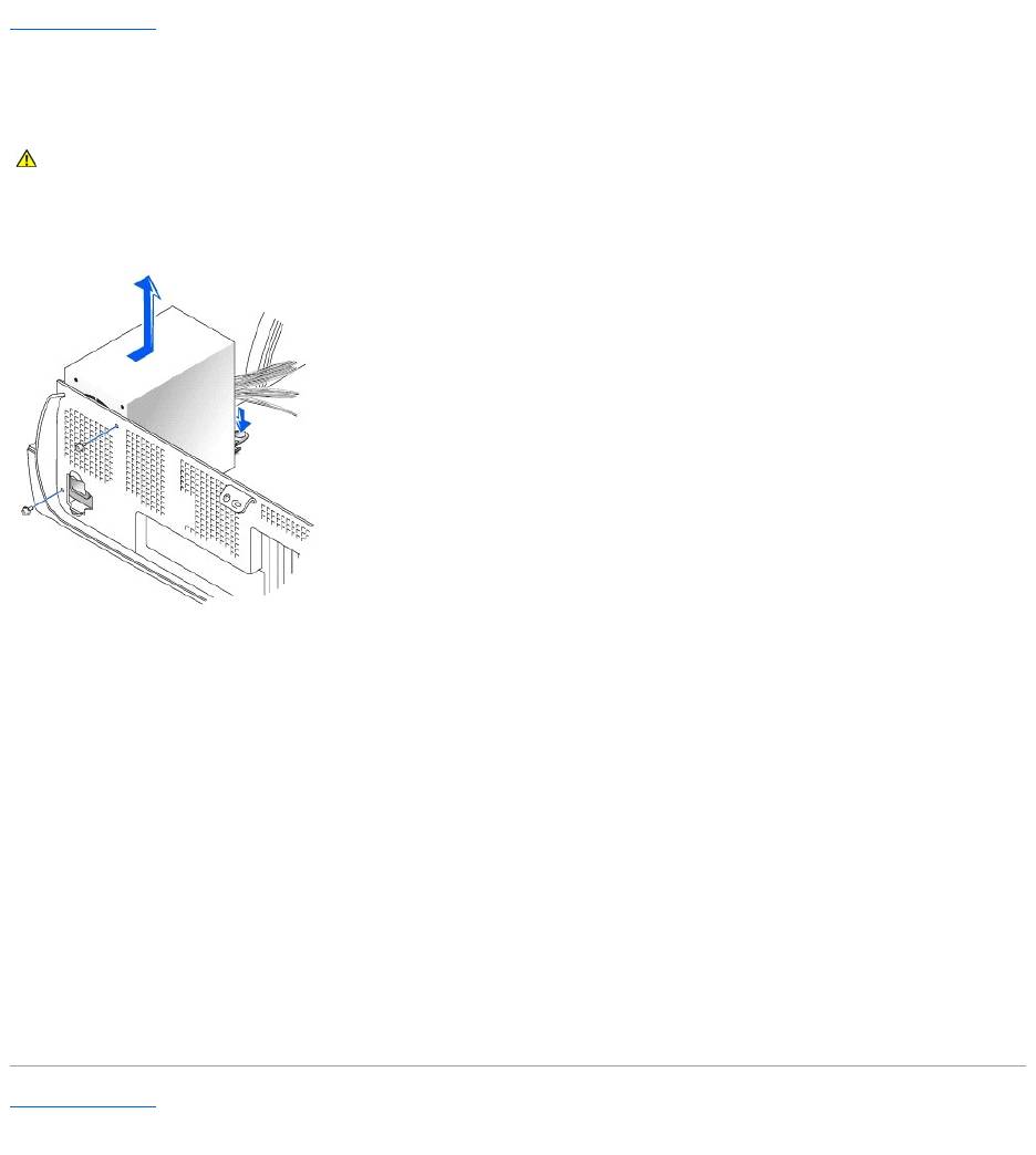
3. Remove the two screws that attach the power supply to the rear wall.
4. Press the release button.
5. Slide the power supply toward the front of the computer approximately 1 inch.
6. Lift the power supply up and out of the computer.
Replacing the Power Supply
1. Slide the power supply into place.
2. Reconnect the DC power cables.
3. Connect the AC power cable to the connector.
4. Run the cables underneath the clips.
5. Press the clips to close them over the cables.
Back to Contents Page
CAUTION: Before you begin any of the procedures in this section, follow the safety instructions in the System Information Guide.
Back to Contents Page
System Board
DellPrecision™Workstation350ServiceManual
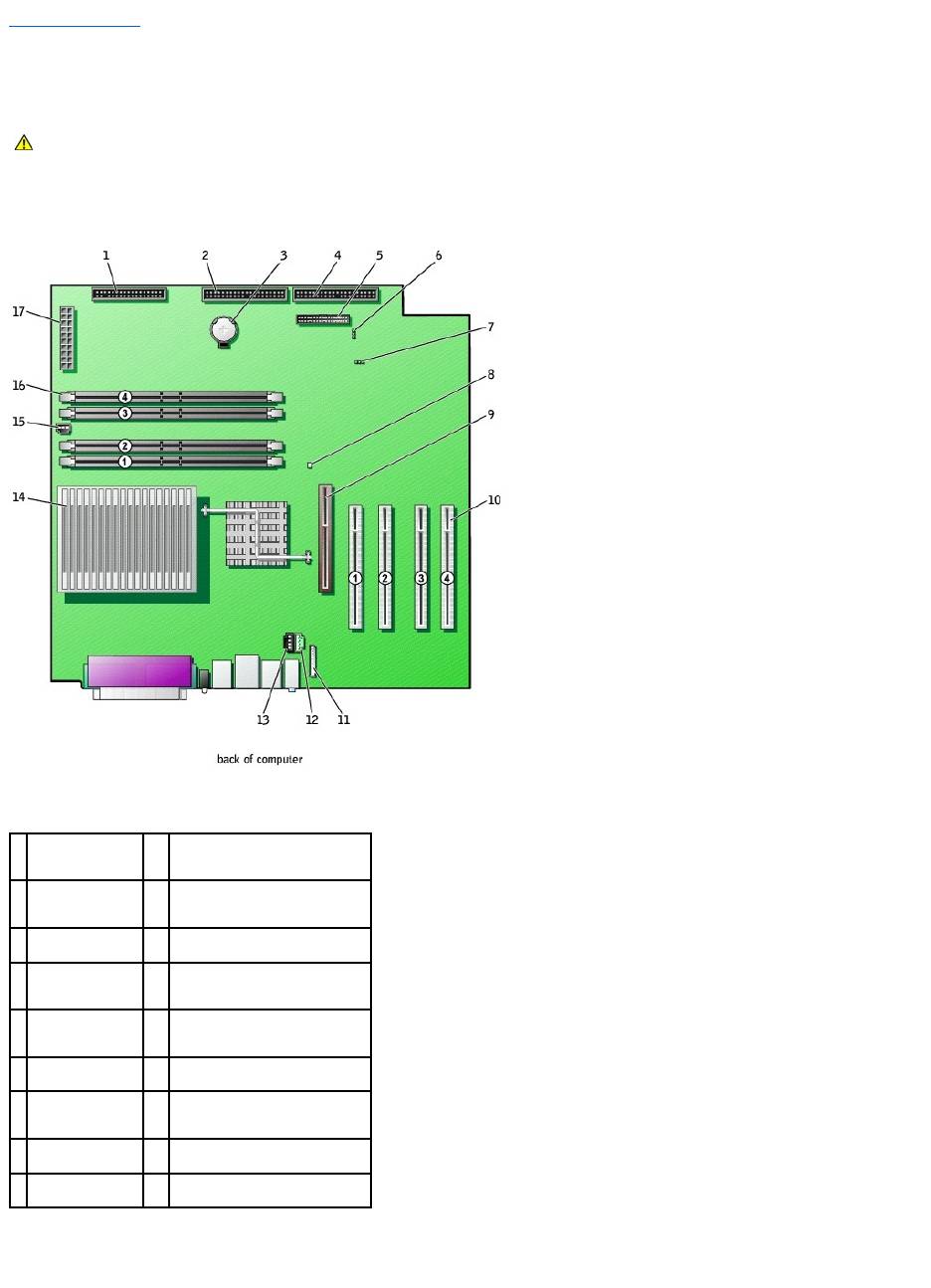
System Board Components
System Board Jumpers
CAUTION: Before you begin any of the procedures in this section, follow the safety instructions in the System Information Guide.
1
floppy drive
connector
(FLOPPY)
10
PCI card connectors (PCI1, PCI2,
PCI3, and PCI4)
2
CD/DVD drive
connector (SEC
IDE)
11
front-panel audio cable connector
(FNT PNL AUD)
3
battery socket
(BATTERY)
12
telephony connector (TELE)
4
hard drive
connector (PRI
IDE)
13
CD drive audio cable connector
(CD)
5
front-panel
connector (FNT
PNL)
14
microprocessor and heat sink
connector (J2E1)
6
password jumper
(PSWD)
15
microprocessor fan connector
(FAN2)
7
clear CMOS
jumper (CLR CM)
16
memory module connectors
(RIMM 1, RIMM 2, RIMM 3, and
RIMM 4)
8
standby power
light (PWR LED)
17
power connector (MAIN POWER)
9
AGP card
connector (J7C1)
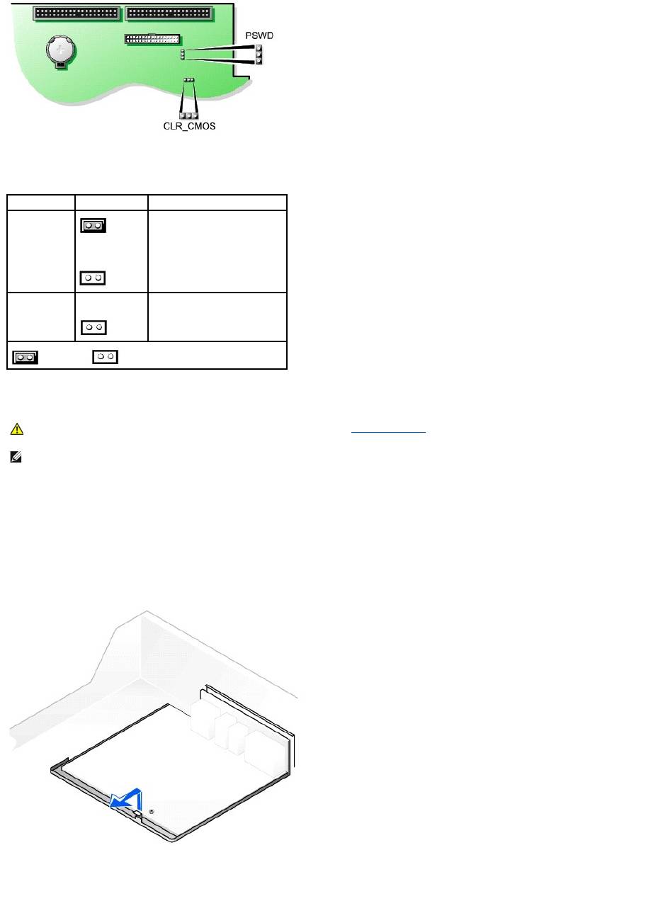
System-Board Jumper Settings
Removing the System Board
1. Remove any components that restrict access to the system board.
2. Disconnect all cables from the system board.
3. Before you remove the existing system board, visually compare the replacement system board to the existing system board to make sure that you have
the correct part.
4. Pull up on the tab and slide the system board toward the front of the computer, and then lift it up and away.
Removing the System Board
5. Place the system board that you just removed next to the replacement system board.
Replacing the System Board
Jumper
Setting
Description
PSWD
(green jumper)
(default)
Password features are enabled.
Password features are disabled.
CLR_CMOS
Clears the CMOS settings
jumpered unjumpered
CAUTION: Before you remove any component from the system board, see "Before You Begin."
NOTE: The system board and metal tray are attached and are removed as one piece.

1. Transfer components from the existing system board to the replacement system board.
2. Remove the memory modules and install them on the replacement board.
3. Remove the heat-sink assembly and microprocessor from the existing system board and transfer them to the replacement system board.
4. Configure the settings of the replacement system board.
5. Set the jumpers on the replacement system board so they are identical to the ones on the existing board.
6. Orient the replacement board by aligning the notches on the bottom to the tabs on the computer floor.
7. Slide the board toward the back of the computer until it clicks into place.
8. Replace any components and cables that you removed from the system board.
Back to Contents Page
CAUTION: The microprocessor package and heat-sink assembly can get hot. To avoid burns, be sure that the package and assembly have had
sufficient time to cool before you touch them.
NOTE: Some components and connectors on the replacement system board may be in different locations from the corresponding connectors on the
existing system board.
- 1
- 2
