Dell Latitude D610 – страница 2
Инструкция к Ноутбуку Dell Latitude D610
Оглавление
- Dell™Latitude™D610ServiceManual

5. Press the hard drive cover down until it is fully seated in the bay, and tighten the screws.
6. Install the operating system for your computer.
7. Install the drivers and utilities for your computer.
Back to Contents Page
Back to Contents Page
Center Control Cover
Dell™Latitude™D610ServiceManual
Removing the Center Control Cover
Installing the Center Control Cover
Removing the Center Control Cover
1. Follow the instructions in "Preparing to Work Inside the Computer."
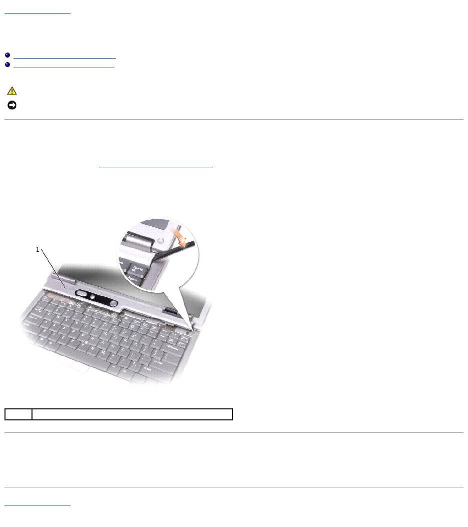
2. Open the display all the way (180 degrees) so that it lies flat against your work surface.
3. Starting on the right side of the computer, use a plastic scribe to gently pry up the center control cover.
Installing the Center Control Cover
Gently snap the center control cover into place starting from left to right.
Back to Contents Page
CAUTION: Before you begin any of the procedures in this section, follow the safety instructions in the Product Information Guide.
NOTICE: To avoid electrostatic discharge, ground yourself by using a wrist grounding strap or by periodically touching an unpainted metal surface (such
as the back panel) on the computer.
1
center control cover
Back to Contents Page
Keyboard
Dell™Latitude™D610ServiceManual
Removing the Keyboard
Installing the Keyboard
Removing the Keyboard
1. Follow the instructions in "Preparing to Work Inside the Computer."
2. Remove the center control cover (see "Removing the Center Control Cover").
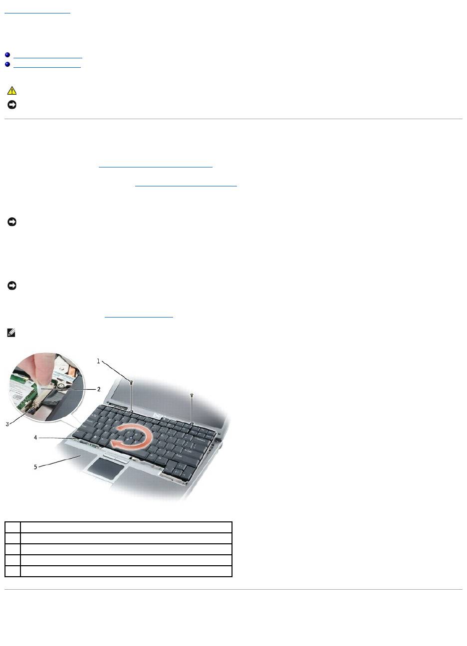
3. Remove the two M2.5 x 5-mm screws across the top of the keyboard.
4. Lift and rotate the keyboard clockwise 90 degrees to access the pull-tab.
5. Using the keyboard cable pull-tab, pull up to disconnect the keyboard cable connector from the keyboard connector on the system board.
6. Remove the keyboard (see "Removing the Keyboard").
Installing the Keyboard
1. Connect the keyboard cable connector to the keyboard connector on the system board.
CAUTION: Before you begin any of the procedures in this section, follow the safety instructions in the Product Information Guide.
NOTICE: To avoid electrostatic discharge, ground yourself by using a wrist grounding strap or by periodically touching an unpainted metal surface (such
as the back panel) on the computer.
NOTICE: When you remove the keyboard, pull up gently to avoid damaging the keyboard cable.
NOTICE: The keycaps on the keyboard are fragile, easily dislodged, and time-consuming to replace. Be careful when removing and handling the
keyboard.
NOTE: When you replace the keyboard, ensure that the keyboard tabs are completely in place to avoid scratching the palm rest.
1
M2.5 x 5-mm screws (2)
2
keyboard cable pull-tab
3
keyboard connector on system board
4
keyboard tabs (5)
5
palm rest

2. Slide the keyboard tabs at the bottom of the keyboard into the base of the computer.
3. Tighten the two M2.5 x 5-mm screws across the top of the keyboard.
4. Replace the center control cover (see "Installing the Center Control Cover").
Back to Contents Page
NOTE: You may need to slightly push the keyboard tabs into the base of the computer.
Back to Contents Page
Base Latch
Dell™Latitude™D610ServiceManual
Removing the Base Latch
Installing the Base Latch
Removing the Base Latch
1. Follow the instructions in "Preparing to Work Inside the Computer."
2. Remove the center control cover (see "Removing the Center Control Cover").
3. Remove the keyboard (see "Removing the Keyboard").
4. Remove the display assembly (see "Removing the Display Assembly").
5. Remove the palm rest (see "Removing the Palm Rest").
6. Remove the speaker assembly (see "Removing the Speaker Assembly").
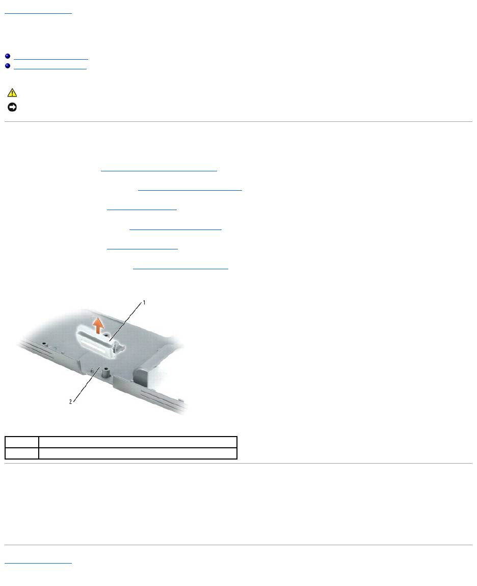
7. Pull the base latch straight up and out of the computer base (no screws secure it in place).
Installing the Base Latch
1. Slide the latch over the notch located in the center of the system base.
2. Replace the speaker assembly to secure the latch in place.
Back to Contents Page
CAUTION: Before you begin any of the procedures in this section, follow the safety instructions in the Product Information Guide.
NOTICE: To avoid electrostatic discharge, ground yourself by using a wrist grounding strap or by periodically touching an unpainted metal surface (such
as the back panel) on the computer.
1
base latch
2
computer base
Back to Contents Page
Mini PCI Card
Dell™Latitude™D610ServiceManual
Removing the Mini PCI Card
Installing the Mini PCI Card
Removing the Mini PCI Card
1. Follow the instructions in "Preparing to Work Inside the Computer.
2. Remove the center control cover (see "Removing the Center Control Cover").
3. Remove the keyboard (see "Removing the Keyboard").
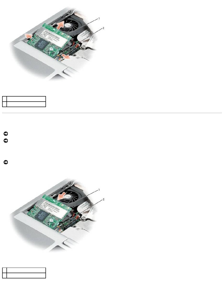
4. Remove the antenna cables from the routing clips.
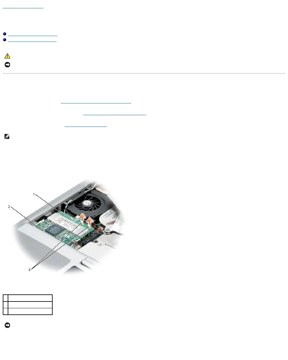
5. Disconnect the antenna cables from the Mini PCI card.
6. Release the Mini PCI card by spreading the metal securing tabs until the card pops up slightly.
7. Remove the Mini PCI card from the Mini PCI card connector at a 45-degree angle.
CAUTION: Before you begin any of the procedures in this section, follow the safety instructions in the Product Information Guide.
NOTICE: To avoid electrostatic discharge, ground yourself by using a wrist grounding strap or by periodically touching an unpainted metal surface (such
as the back panel) on the computer.
NOTE: If a Mini PCI card is not already installed, install the Mini PCI card. If you are replacing a Mini PCI card, remove the existing card:
1
Mini PCI card
2
Mini PCI card connector
3
antenna cables (2)
NOTICE: To prevent damage to the Mini PCI card connector, do not use tools to spread the securing clips that secure the card.
Installing the Mini PCI Card
1. Align the Mini PCI card with the connector at a 45-degree angle, and press the Mini PCI card into the connector until it clicks.
2. Connect the antenna cables to the Mini PCI card.
1
Mini PCI card
2
metal securing tabs (2)
NOTICE: To avoid damaging the antenna cables or the Mini PCI card, never place the cables under the card.
NOTICE: The connectors are keyed to ensure correct insertion. If you feel resistance, check the connectors and realign the card.
NOTICE: Ensure the antenna cables are properly secured by the routing clips on the left side of the fan. Failure to do so may cause damage to the
antenna cables and the fan.
1
Mini PCI card
2
metal securing tabs (2)
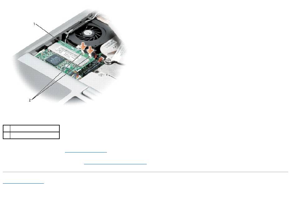
3. Replace the keyboard (see "Installing the Keyboard").
4. Replace the center control cover (see "Installing the Center Control Cover").
Back to Contents Page
1
Mini PCI card
2
antenna wires (2)
Back to Contents Page
Palm Rest
Dell™Latitude™D610ServiceManual
Removing the Palm Rest
Installing the Palm Rest
Removing the Palm Rest
1. Follow the instructions in "Preparing to Work Inside the Computer."
2. Remove the center control cover (see "Removing the Center Control Cover").
3. Remove the keyboard (see "Removing the Keyboard").
4. Remove the display assembly (see "Removing the Display Assembly").
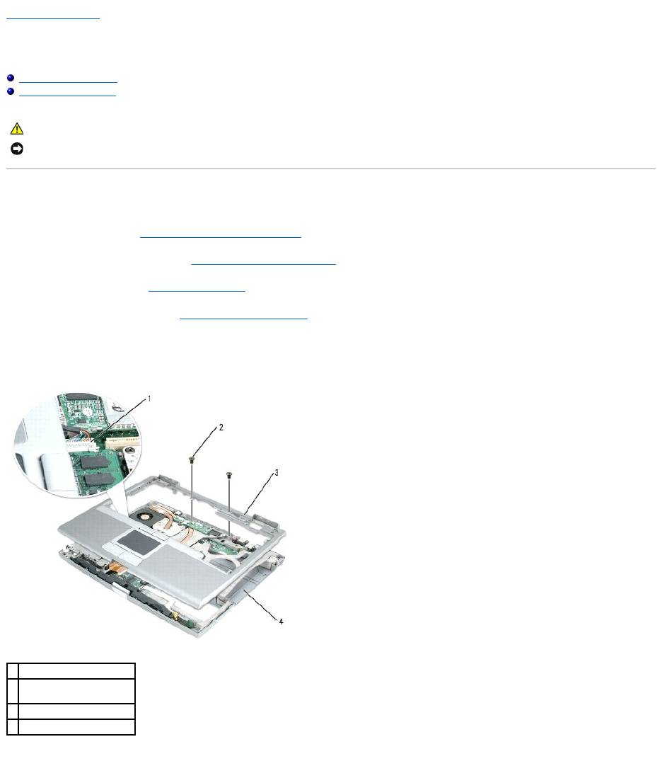
5. Remove the two M2.5 x 5-mm screws from the top of the palm rest.
6. Disconnect the touch pad cable from the connector on the system board.
7. Turn the computer over and remove the thirteen M2.5 x 8-mm screws.
CAUTION: Before you begin any of the procedures in this section, follow the safety instructions in the Product Information Guide.
NOTICE: To avoid electrostatic discharge, ground yourself by using a wrist grounding strap or by periodically touching an unpainted metal surface (such
as the back panel) on the computer.
1
touch pad connector
2
screws (2) at top of palm
rest
3
palm rest
4
computer base
8. Starting at the back center of the palm rest, use your fingers to separate the palm rest from the computer base by lifting the inside of the palm rest
while pushing in on the outside.
Installing the Palm Rest
1. Align the palm rest with the computer base and snap into place.
2. Connect the touch pad cable to the connector on the system board.
3. Replace the three M2.5 x 5-mm screws on the top of the palm rest.
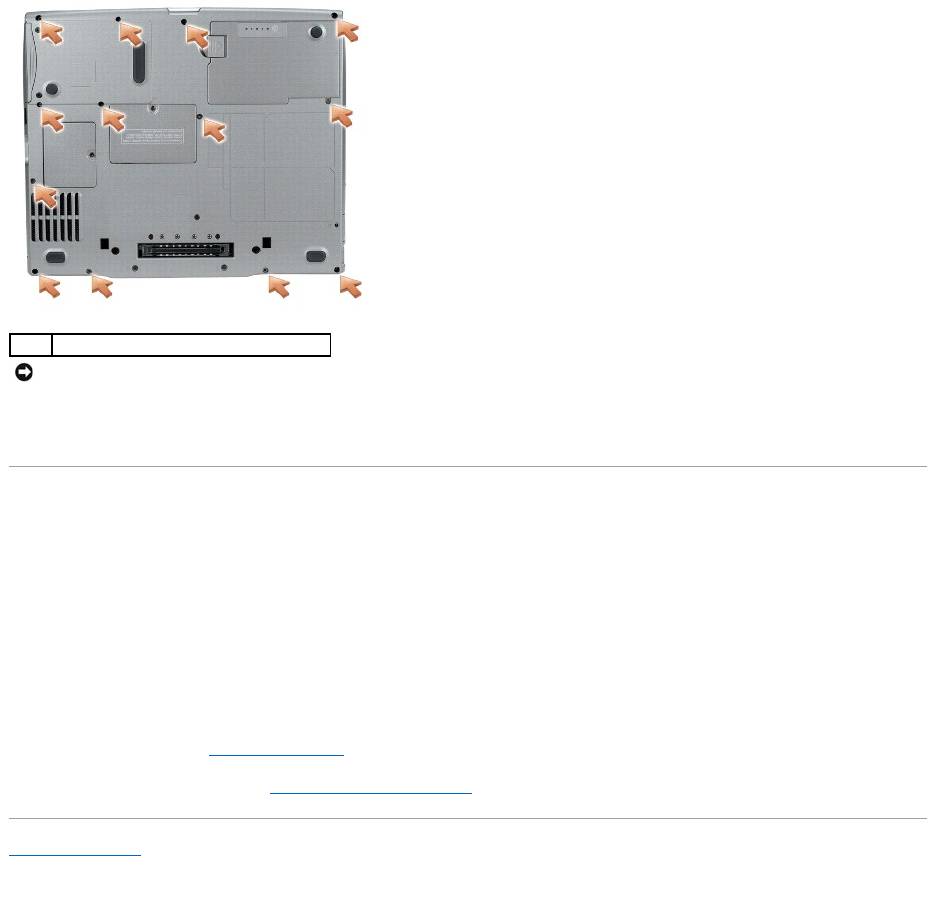
4. Turn the computer over and replace the thirteen M2.5 x 8-mm screws.
5. Replace the display assembly.
6. Replace the keyboard (see "Installing the Keyboard").
7. Replace the center control cover (see "Installing the Center Control Cover").
Back to Contents Page
1
M2.5 x 8-mm screws (13)
NOTICE: Carefully separate the palm rest from the computer base to avoid damage to the palm rest.
Back to Contents Page
Pin Assignments for I/O Connectors
Dell™Latitude™D610ServiceManual
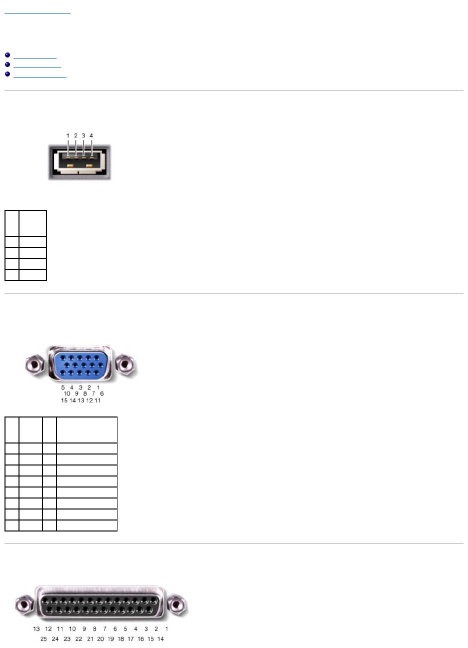
USB Connector
Video Connector
Parallel Connector
USB Connector
Video Connector
Parallel Connector
Pin
Signal
1
USB5V+
2
USBP–
3
USBP+
4
GND
Pin
Signal
Pin
Signal
1
CRT_R
9
5V+
2
CRT_G
10
GND
3
CRT_B
11
MONITOR_DETECT–
4
NC
12
DDC_DATA
5
GND
13
CRT_HS
6
GND
14
CRT_VS
7
GND
15
DDC_CLK
8
GND

Back to Contents Page
Pin
Signal
Pin
Signal
1
STROBE–
10
ACK–
2
PD0
11
BUSY
3
PD1
12
PE
4
PD2
13
SLCT
5
PD3
14
AFD/3M–
6
PD4
15
ERROR–
7
PD5
16
INIT–
8
PD6
17
SLIN–
9
PD7
18-25
GND
Back to Contents Page
Speaker Assembly
Dell™Latitude™D610ServiceManual
Removing the Speaker Assembly
Installing the Speaker Assembly
Removing the Speaker Assembly
1. Follow the instructions in "Preparing to Work Inside the Computer."
2. Remove the center control cover (see "Removing the Center Control Cover").
3. Remove the keyboard (see "Removing the Keyboard").
4. Remove the display assembly (see "Removing the Display Assembly").
5. Remove the palm rest (see "Removing the Palm Rest").
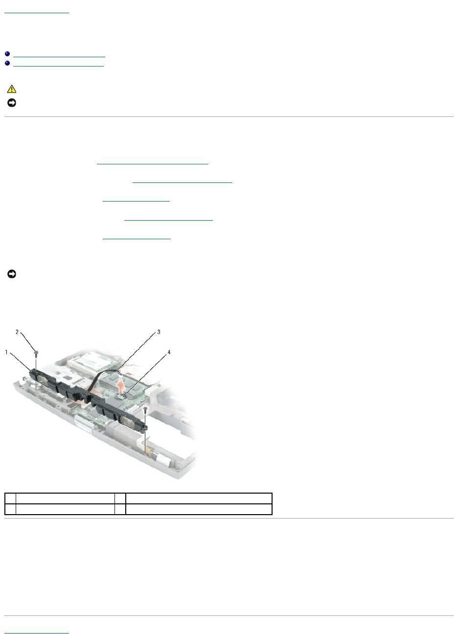
6. Disconnect the speaker cable from the speaker connector on the system board.
7. Remove the two M2.5 x 5-mm screws (one on each side) from the speaker assembly.
8. Remove the speaker assembly by pulling it straight up and out of the computer base.
Installing the Speaker Assembly
1. Slide the speaker assembly over the notch located in the center of the computer base.
2. Replace the two M2.5 x 5-mm screws (one on each side) on the speaker assembly.
3. Reconnect the speaker cable to the speaker connector on the system board.
Back to Contents Page
CAUTION: Before you begin any of the procedures in this section, follow the safety instructions in the Product Information Guide.
NOTICE: To avoid electrostatic discharge, ground yourself by using a wrist grounding strap or by periodically touching an unpainted metal surface (such
as the back panel) on the computer.
NOTICE: Handle the speaker assembly with care to avoid damaging it.
1
speaker assembly
3
speaker cable
2
M2.5 x 5-mm screws (2)
4
speaker connector on system board

Back to Contents Page
System Board
Dell™Latitude™D610ServiceManual
Removing the System Board
Installing the System Board
Removing the System Board
The system board's BIOS chip contains the Service Tag, which is also visible on a barcode label on the bottom of the computer. The replacement kit for the
system board includes a CD that provides a utility for transferring the Service Tag to the replacement system board.
1. Follow the instructions in "Preparing to Work Inside the Computer."
2. Remove the center control cover (see "Removing the Center Control Cover").
3. Remove the keyboard (see "Removing the Keyboard").
4. Remove the display assembly (see "Removing the Display Assembly").
5. Remove the palm rest (see "Removing the Palm Rest").
6. Remove the fan (see "Removing the Fan").
7. Remove the microprocessor thermal-cooling assembly (see "Removing the Microprocessor Thermal-Cooling Assembly").
8. Remove the microprocessor (see "Removing the Microprocessor Module").
9. Remove the speaker assembly (see "Removing the Speaker Assembly").
10. Remove the internal card with Bluetooth® wireless technology (see step #4).
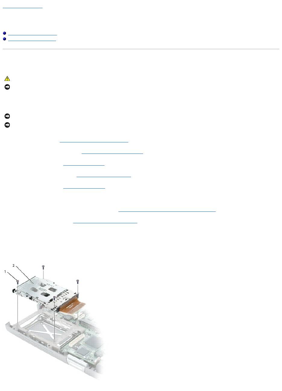
11. Remove the four M2x3 screws that secure the PCMCIA card cage to the system board.
CAUTION: Before you begin any of the procedures in this section, follow the safety instructions in the Product Information Guide.
NOTICE: To avoid electrostatic discharge, ground yourself by using a wrist grounding strap or by periodically touching an unpainted metal surface (such
as the back panel) on the computer.
NOTICE: Disconnect the computer and any attached devices from electrical outlets, and remove any installed batteries.
NOTICE: To avoid electrostatic discharge, ground yourself by using a wrist grounding strap or by touching an unpainted metal surface on the computer.
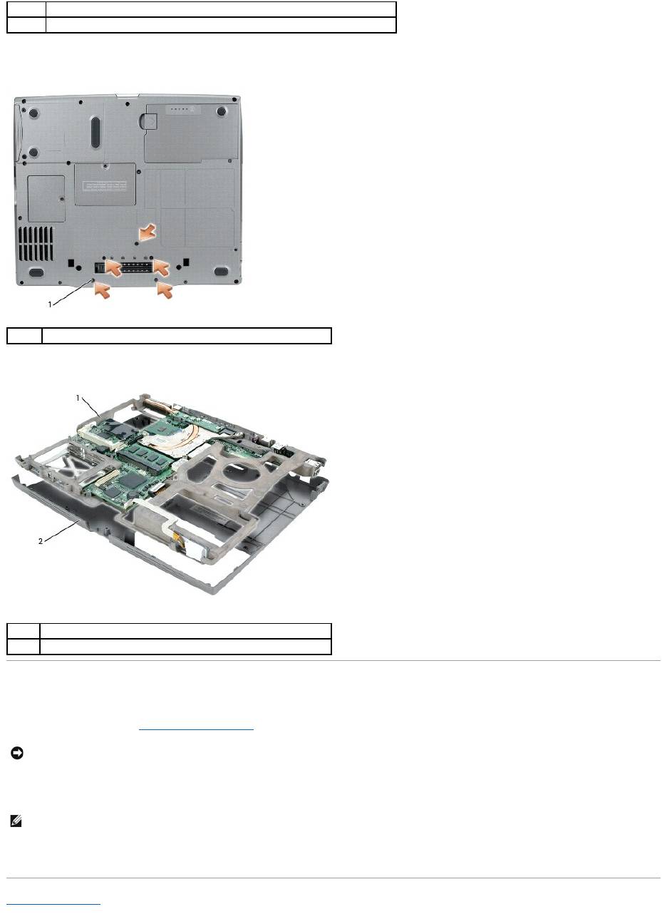
12. Turn the computer over and remove the five M2 x 3-mm screws labeled "B" that secure the system board assembly to the computer base.
13. Pull out the system board assembly starting from the front of the palm rest.
Installing the System Board
1. Follow all of the steps in "Removing the System Board" in reverse order.
2. Turn on the computer.
3. Insert the CD that accompanied the replacement system board into the appropriate drive. Follow the instructions that appear on the screen.
Back to Contents Page
1
M2.5 x 4-mm screws (4)
2
PCMCIA card cage
1
M2 x 3-mm screws (5)
1
system board assembly
2
computer base
NOTICE: Before turning on the computer, replace all screws and ensure that no stray screws remain inside the computer. Failure to do so may result in
damage to the computer.
NOTE: After replacing the system board, enter the computer Service Tag into the BIOS of the replacement system board.

Back to Contents Page
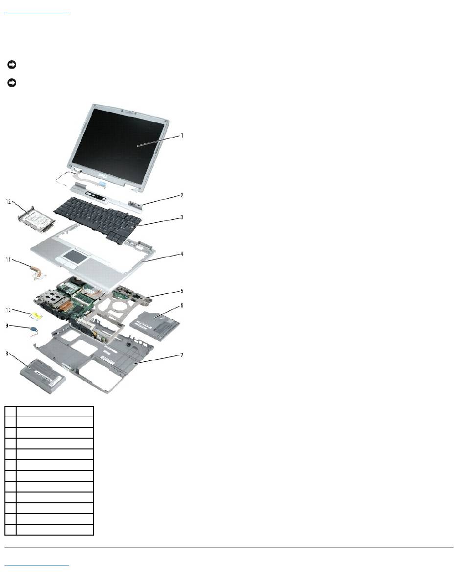
System Components
Dell™Latitude™D610ServiceManual
Back to Contents Page
NOTICE: Only a certified service technician should perform repairs on your computer. Damage due to servicing that is not authorized by Dell is not
covered by your warranty.
NOTICE: Unless otherwise noted, each procedure in this document assumes that a part can be replaced by performing the removal procedure in
reverse order.
1
display assembly
2
center control cover
3
keyboard
4
palm rest
5
system board assembly
6
optical device
7
computer base
8
primary battery
9
coin-cell battery
10
modem
11
thermal cooling assembly
12
hard drive
Back to Contents Page
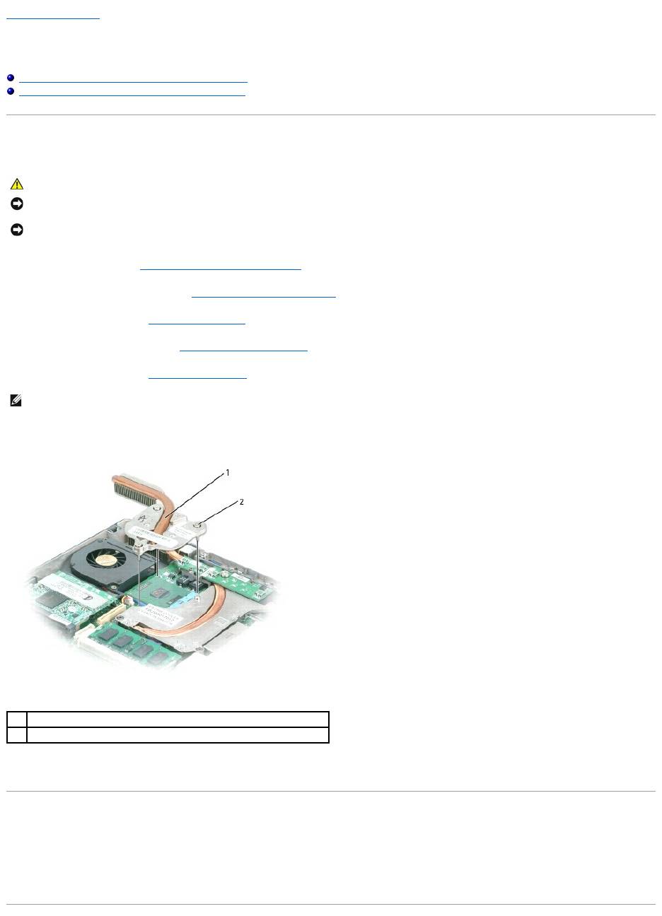
Microprocessor Thermal-Cooling Assembly
Dell™Latitude™D610ServiceManual
Removing the Microprocessor Thermal-Cooling Assembly
Installing the Microprocessor Thermal-Cooling Assembly
Removing the Microprocessor Thermal-Cooling Assembly
1. Follow the instructions in "Preparing to Work Inside the Computer."
2. Remove the center control cover (see "Removing the Center Control Cover").
3. Remove the keyboard (see "Removing the Keyboard").
4. Remove the display assembly (see "Removing the Display Assembly").
5. Remove the palm rest (see "Removing the Palm Rest").
6. Loosen in consecutive order the three captive screws, labeled "1" through "3," that secure the microprocessor thermal-cooling assembly to the system
board.
7. Lift to remove the microprocessor thermal-cooling assembly away from the system board.
Installing the Microprocessor Thermal-Cooling Assembly
1. Place the microprocessor thermal-cooling assembly on the system board.
2. Tighten the three captive screws, labeled "1" through "3," in consecutive order.
CAUTION: Before you begin any of the procedures in this section, follow the safety instructions in the Product Information Guide.
NOTICE: To avoid electrostatic discharge, ground yourself by using a wrist grounding strap or by periodically touching an unpainted metal surface (such
as the back panel) on the computer.
NOTICE: Disconnect the computer and any attached devices from electrical outlets, and remove any installed batteries.
NOTE: You can remove the microprocessor thermal-cooling assembly with the fan attached.
1
microprocessor thermal-cooling assembly
2
captive screws (3)

Back to Contents Page
