Dell Latitude D500 – страница 2
Инструкция к Ноутбуку Dell Latitude D500
Оглавление
- Dell™ Latitude™ D500 Service Manual
Back to Contents Page
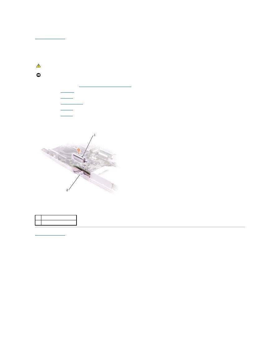
Base Latch
Dell™ Latitude™ D500 Service Manual
1.
Follow the instructions in "
Preparing to Work Inside the Computer
."
2.
Remove the
hard drive
.
3.
Remove the
keyboard
.
4.
Remove the
display assembly
.
5.
Remove the
palm rest
.
6.
Remove the
speakers
.
7.
Pull the base latch straight up and away from the computer base.
Back to Contents Page
CAUTION:
Before performing the following procedures, read the safety instructions in your
System Information Guide
.
NOTICE:
To avoid electrostatic discharge, ground yourself by using a wrist grounding strap or by periodically touching an unpainted metal surface (such
as the back panel) on the computer.
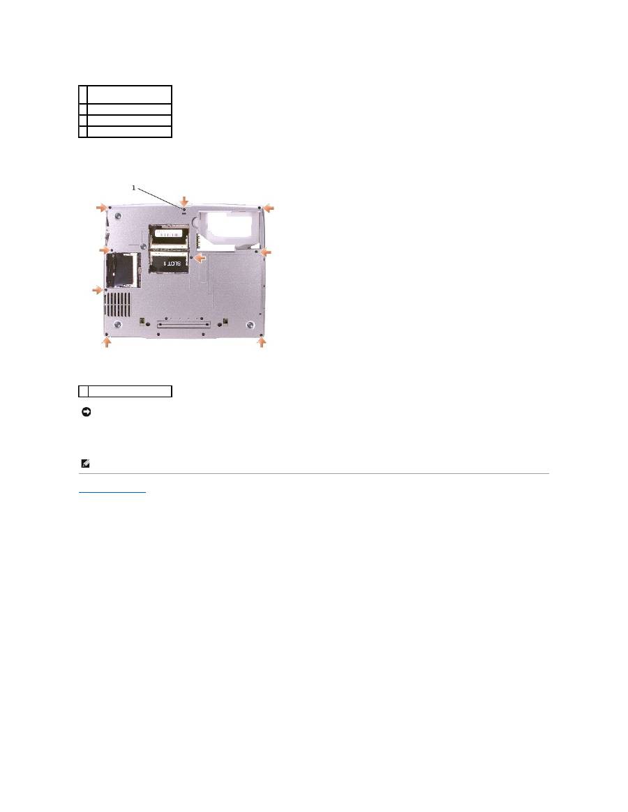
1
base latch
2
computer base
Back to Contents Page
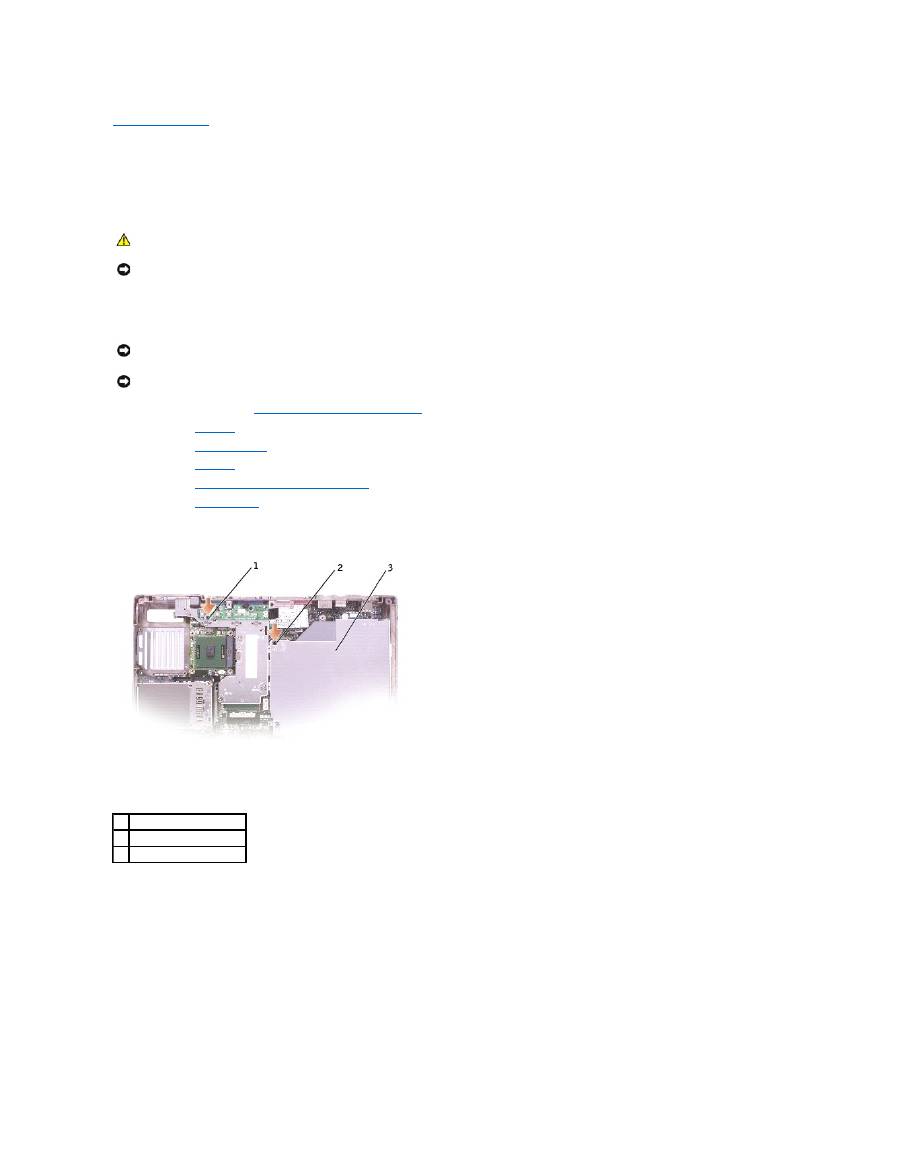
Modem
Dell™ Latitude™ D500 Service Manual
1.
Follow the instructions in "
Preparing to Work Inside the Computer
."
2.
Remove the
keyboard
.
3.
Remove the
display assembly
.
4.
Remove the
palm rest
.
5.
Remove the M2 x 3-mm screw.
6.
Disconnect the modem cable from the modem.
7.
Pull up on the pull-tab to disconnect the modem from the system board connector.
CAUTION:
Before performing the following procedures, read the safety instructions in your
System Information Guide
.
NOTICE:
To avoid electrostatic discharge, ground yourself by using a wrist grounding strap or by periodically touching an unpainted metal surface (such
as the back panel) on the computer.
1 modem
4 system board connector
2 pull-tab
5 modem cable
3 M2 x 3-mm screw
NOTICE:
Do not disconnect the modem cable from the system board.
NOTICE:
Ensure that the modem cable is routed correctly when you replace the modem.
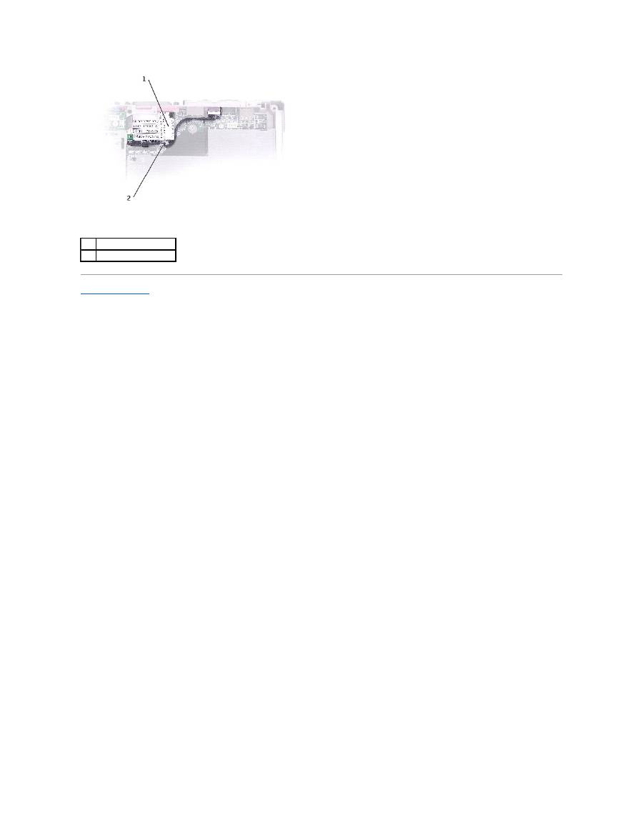
Back to Contents Page
1
modem
2
modem cable
Back to Contents Page
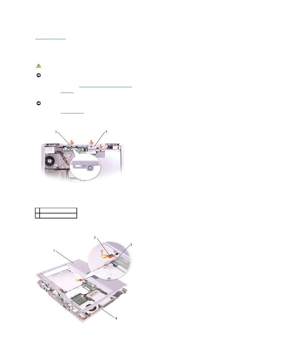
Palm Rest
Dell™ Latitude™ D500 Service Manual
1.
Follow the instructions in "
Preparing to Work Inside the Computer
."
2.
Remove the
keyboard
.
3.
Remove the
display assembly
.
4.
Remove the three M2 x 3-mm screws labeled "circle P" from the top of the palm rest.
5.
Disconnect the touch pad connector from the system board.
CAUTION:
Before performing the following procedures, read the safety instructions in your
System Information Guide
.
NOTICE:
To avoid electrostatic discharge, ground yourself by using a wrist grounding strap or by periodically touching an unpainted metal surface (such
as the back panel) on the computer.
NOTICE:
You must remove the display assembly before you remove the palm rest; the display hinges pass through the back of the palm rest.
1 M2 x 3-mm screws (3)
2 top of the palm rest
6.
Turn the computer over and remove the nine M2.5 x 8-mm screws.
7.
Starting at the back center of the palm rest, use your fingers to separate the palm rest from the computer base by lifting the inside of the palm rest
while pushing in on the outside.
Back to Contents Page
1 back center of the palm
rest
2 touch pad connector
3 system board connector
4 computer base
1 M2.5 x 8-mm screws (9)
NOTICE:
Carefully separate the palm rest from the computer base to avoid damage to the palm rest.
NOTE:
When you reinstall the palm rest, attach the right side of the palm rest first.
Back to Contents Page
Pin Assignments for I/O Connectors
Dell™ Latitude™ D500 Service Manual
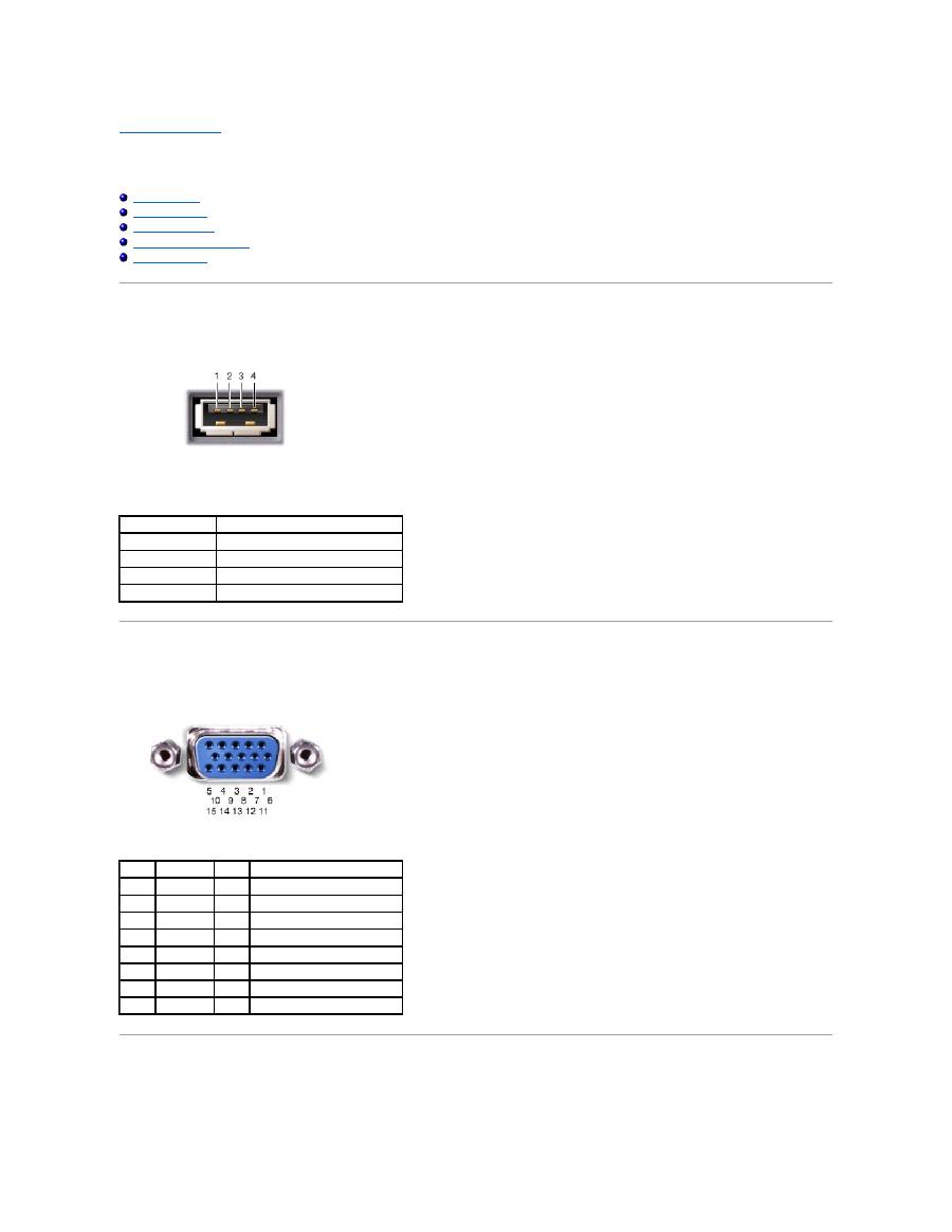
USB Connector
Video Connector
Parallel Connector
S-Video TV-Out Connector
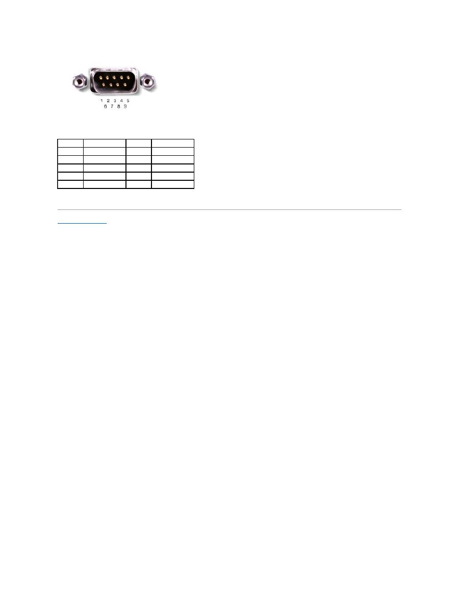
Serial Connector
USB Connector
Video Connector
Parallel Connector
Pin
Signal
1
USB5V+
2
USBP
–
3
USBP+
4
GND
Pin
Signal
Pin
Signal
1
CRT_R
9
5V+
2
CRT_G
10
GND
3
CRT_B
11
MONITOR_DETECT
–
4
NC
12
DDC_DATA
5
GND
13
CRT_HS
6
GND
14
CRT_VS
7
GND
15
DDC_CLK
8
GND
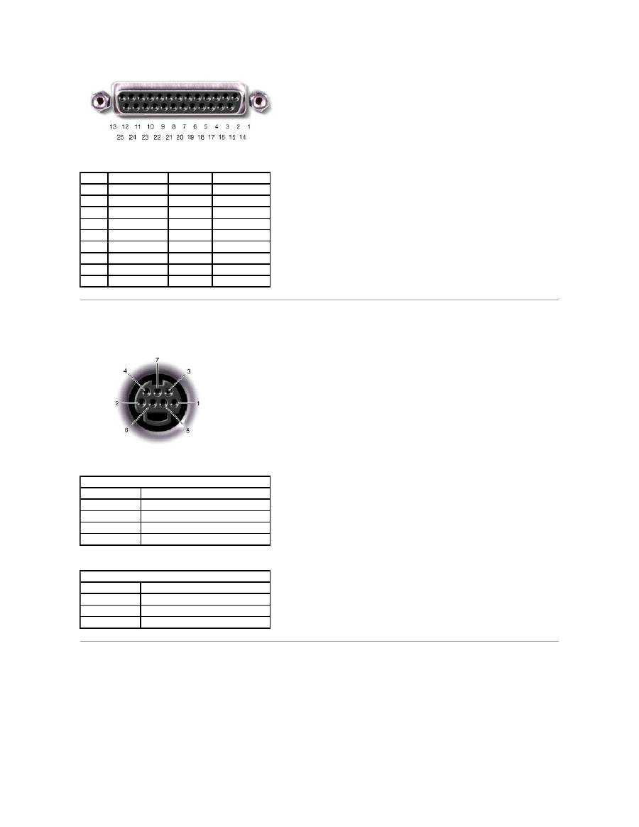
S-Video TV-Out Connector
Serial Connector
Pin
Signal
Pin
Signal
1
STROBE
–
10
ACK
–
2
PD0
11
BUSY
3
PD1
12
P E
4
PD2
13
SLCT
5
PD3
14
AFD/3M
–
6
PD4
15
ERROR
–
7
PD5
16
INIT
–
8
PD6
17
SLIN
–
9
PD7
18
–
25
GND
S-Video
Pin
Signal
1
GND
2
GND
3
DLUMA-L
4
DCRMA-L
Composite Video
Pin
Signal
5
NC
6
DCMPS-L
7
GND
Back to Contents Page
Pin
Signal
Pin
Signal
1
DCD
6
DSR
2
RXDA
7
RTS
3
TXDA
8
CTS
4
DTR
9
RI
5
GND
Back to Contents Page
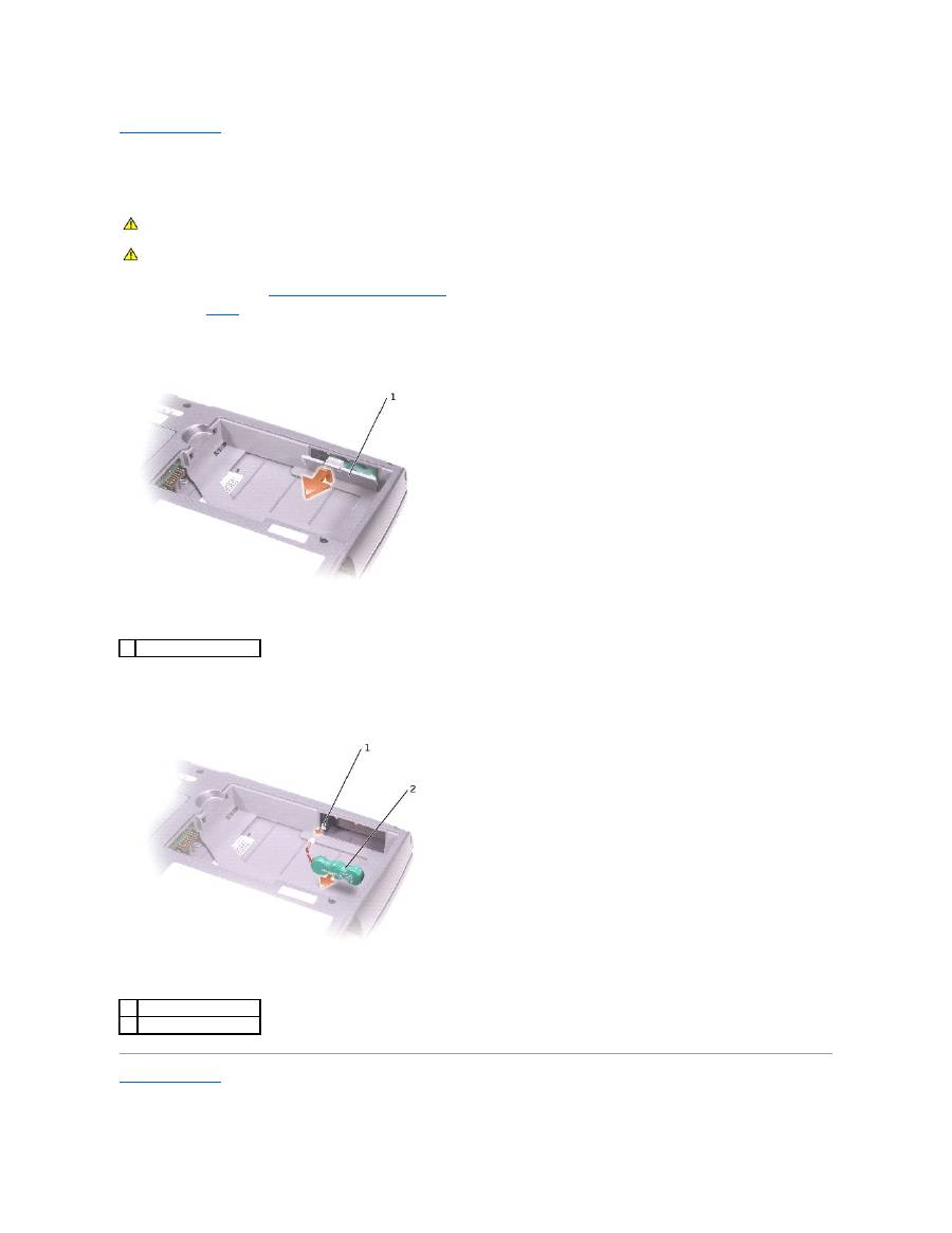
Reserve Battery
Dell™ Latitude™ D500 Service Manual
1.
Follow the instructions in "
Preparing to Work Inside the Computer
."
2.
Remove the
battery
.
3.
Depress the battery latch and rotate it out to remove the reserve battery cover.
4.
Pull the reserve battery straight out of the computer base.
5.
Disconnect the reserve-battery cable connector from the battery connector.
Back to Contents Page
CAUTION:
Before working inside your Dell™ computer, read the safety instructions in your
System Information
Guide
.
CAUTION:
To prevent static damage to components inside your computer, discharge static electricity from your body before you touch any of
your computer's electronic components. You can do so by touching an unpainted metal surface.
1 reserve battery cover
1
battery connector
2
reserve battery
Back to Contents Page
Speakers
Dell™ Latitude™ D500 Service Manual
1.
Follow the instructions in "
Preparing to Work Inside the Computer
."
2.
Remove the
keyboard
.
3.
Remove the
display assembly
.
4.
Remove the
palm rest
.
5.
Disconnect the speaker connector from the system board connector.
6.
Remove the M2.5 x 8-mm screw from the speakers.
7.
Remove the M2.5 x 4-mm screw from the speakers.
8.
Remove the speakers by pulling them straight up and out of the computer base.
9.
Remove the
reserve battery
from the speakers.
Back to Contents Page
CAUTION:
Before performing the following procedures, read the safety instructions in your
System Information Guide
.
NOTICE:
To avoid electrostatic discharge, ground yourself by using a wrist grounding strap or by periodically touching an unpainted metal surface (such
as the back panel) on the computer.
NOTICE:
Handle the speakers with care to avoid damaging them.
1 speaker
5 M2.5 x 4-mm screw
2 speaker connector
6 computer base
3 system board connector
7 M2.5 x 8-mm screw
4 reserve battery
Back to Contents Page
System Board
Dell™ Latitude™ D500 Service Manual
Removing the System Board
The system board's BIOS chip contains the Service Tag, which is also visible on a barcode label on the bottom of the computer. The replacement kit for the
system board includes a CD that provides a utility for transferring the Service Tag to the replacement system board.
1.
Follow the instructions in "
Preparing to Work Inside the Computer
."
2.
Remove the
keyboard
.
3.
Remove the
display assembly
.
4.
Remove the
palm rest
.
5.
Remove the
microprocessor thermal-cooling assembly
.
6.
Remove the
microprocessor
.
7.
Remove the one M2.5 x 8-mm screw and one M2.5 x 4-mm screw labeled "circle B."
CAUTION:
Before performing the following procedures, read the safety instructions in your
System Information Guide
.
NOTICE:
To avoid electrostatic discharge, ground yourself by using a wrist grounding strap or by periodically touching an unpainted metal surface (such
as the back panel) on the computer.
NOTICE:
Disconnect the computer and any attached devices from electrical outlets, and remove any installed batteries.
NOTICE:
To avoid electrostatic discharge, ground yourself by using a wrist grounding strap or by touching an unpainted metal surface on the computer.
1
M2.5 x 4-mm screw
2
M2.5 x 8-mm screw
3
system board
8.
Remove the four M2 x 3-mm screws labeled "circle B" that secure the system board to the computer base.
9.
Pull out the system board starting from the front of the computer.
Installing the System Board
1.
Follow all of the steps in "
Removing the System Board
" in reverse order.
2.
Turn on the computer.
3.
Insert the floppy disk or CD that accompanied the replacement system board into the appropriate drive. Follow the instructions that appear on the
screen.
Back to Contents Page
1 M2 x 3-mm screws (4)
NOTICE:
Before turning on the computer, replace all screws and ensure that no stray screws remain inside the computer. Failure to do so may result in
damage to the computer.
NOTE:
After replacing the system board, enter the computer Service Tag into the BIOS of the replacement system board.
Back to Contents Page
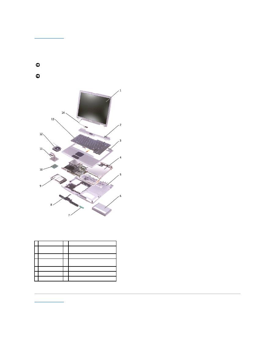
System Components
Dell™ Latitude™ D500 Service Manual
Back to Contents Page
NOTICE:
Only a certified service technician should perform repairs on your computer. Damage due to servicing that is not authorized by Dell is not
covered by your warranty.
NOTICE:
Unless otherwise noted, each procedure in this document assumes that a part can be replaced by performing the removal procedure in
reverse order.
1 display assembly 8
speakers
2 center control
cover
9
hard drive
3 palm rest
10 microprocessor
4 system board
11 microprocessor thermal-cooling
assembly
5 computer base
12 fan
6 battery
13 keyboard
7 reserve battery
14 display cable
Back to Contents Page
Microprocessor Thermal-Cooling Assembly
Dell™ Latitude™ D500 Service Manual
Removing the Microprocessor Thermal-Cooling Assembly
1.
Follow the instructions in "
Preparing to Work Inside the Computer
."
2.
Remove the
keyboard
.
3.
Loosen in consecutive order the four captive screws, labeled "1" through "4," that secure the microprocessor thermal-cooling assembly to the system
board.
4.
Rotate the microprocessor thermal-cooling assembly up toward the side of the computer and away from the system board.
Installing the Microprocessor Thermal-Cooling Assembly
1.
Place the left side of the microprocessor thermal-cooling assembly under the palm rest and rotate the assembly onto the system board.
2.
Tighten the four captive screws, labeled "1" through "4," in consecutive order.
Back to Contents Page
CAUTION:
Before performing the following procedures, read the safety instructions in your
System Information Guide
.
NOTICE:
To avoid electrostatic discharge, ground yourself by using a wrist grounding strap or by periodically touching an unpainted metal surface (such
as the back panel) on the computer.
NOTICE:
Disconnect the computer and any attached devices from electrical outlets, and remove any installed batteries.
NOTE:
You can remove the microprocessor thermal-cooling assembly with the fan attached.
1 microprocessor thermal-
cooling assembly
2 captive screws (4)

Back to Contents Page
Dell™ Latitude™ D500 Service Manual
Information in this document is subject to change without notice.
© 2003 Dell Computer Corporation. All rights reserved.
Reproduction in any manner whatsoever without the written permission of Dell Computer Corporation
is strictly forbidden.
Trademarks used in this text:
Dell
, the
DELL
logo, and
Latitude
are trademarks of Dell Computer Corporation;
Intel
is a registered trademarks of Intel Corporation;
Microsoft
and
Windows
are registered trademarks of Microsoft Corporation;
Bluetooth
is a trademark owned by Bluetooth SIG, Inc. and is used by Dell Computer Corporation under license.
Other trademarks and trade names may be used in this document to refer to either the entities claiming the marks and names or their products. Dell Computer Corporation
disclaims any proprietary interest in trademarks and trade names other than its own.
Model PP05L
April 2003 Rev. A00
Back to Contents Page
NOTE:
A NOTE indicates important information that helps you make better use of your computer.
NOTICE:
A NOTICE indicates either potential damage to hardware or loss of data and tells you how to avoid the problem.
CAUTION:
A CAUTION indicates a potential for property damage, personal injury, or death.
Back to Contents Page
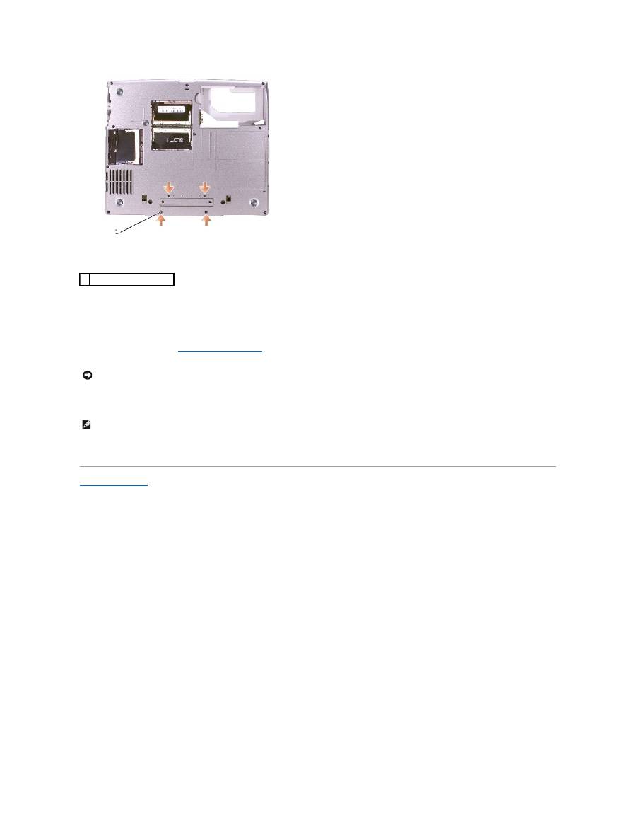
Memory Module, Mini PCI Card, and Devices
Dell™ Latitude™ D500 Service Manual
Memory Module
Mini PCI Card
Devices
Memory Module
1.
Follow the instructions in "
Preparing to Work Inside the Computer
."
2.
Turn the computer over, loosen the captive screw from the memory module cover, and lift the cover.
3.
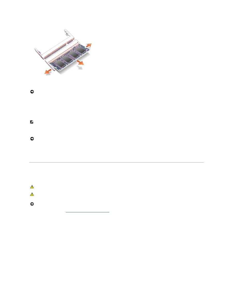
If you are replacing a memory module, remove the existing module.
a.
Use your fingertips to carefully spread apart the securing clips on each end of the memory module connector until the module pops up.
b.
Remove the module from the connector.
CAUTION:
Before working inside your Dell™ computer, read the safety instructions in your
System Information
Guide
.
CAUTION:
To prevent static damage to components inside your computer, discharge static electricity from your body before you touch any of
your computer's electronic components. You can do so by touching an unpainted metal surface.
NOTE:
Memory modules purchased from Dell are covered under your computer warranty.
NOTICE:
To prevent damage to the memory module connector, do not use tools to spread the securing clips that secure the memory module.
NOTICE:
Handle memory modules by their edges, and do not touch the components on a module.
4.
Ground yourself and install the new memory module:
a.
Align the notch in the module with the slot in the center of the connector.
b.
Slide the edge of the module firmly into the connector, and rotate the module down until you feel a click. If you do not feel the click, remove the
module and reinstall it.
5.
Replace the cover and screw.
6.
Insert the battery into the battery bay, or connect the AC adapter to your computer and an electrical outlet.
7.
Turn on the computer.
As the computer boots, it detects the additional memory and automatically updates the system configuration information.
Mini PCI Card
If you ordered a Mini PCI card at the same time that you ordered your computer, Dell has already installed the card for you.
1.
Follow the instructions in "
Preparing to Work Inside the Computer
."
2.
Turn the computer over, and loosen the captive screw on the Mini PCI card cover.
NOTICE:
If you need to install memory modules in two connectors, install a memory module in the connector labeled "JDIM (Slot 1)" before you install a
module in the connector labeled "JDIM2."
NOTE:
If the memory module is not installed properly, the computer does not boot. No error message indicates this failure.
NOTICE:
If the memory module cover is difficult to close, remove the module and reinstall it. Forcing the cover to close may damage your computer.
CAUTION:
Before working inside your computer, read the safety instructions in your
System Information
Guide
.
CAUTION:
To prevent static damage to components inside your computer, discharge static electricity from your body before you touch any of
your computer's electronic components. You can do so by touching an unpainted metal surface.
NOTICE:
Handle components and cards by their edges, and avoid touching pins and contacts.
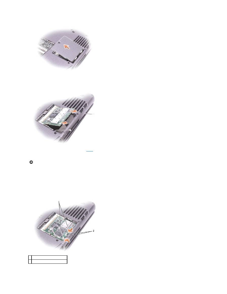
3.
Place your finger under the cover at the indentation, lift up the cover, and slide the cover open.
4.
If a Mini PCI card is not already installed, go to
step 5
. If you are replacing a Mini PCI card, remove the existing card:
a.
Disconnect the Mini PCI card from any attached cables.
b.
Release the Mini PCI card by spreading the securing clips until the card pops up slightly.
c.
Lift the Mini PCI card out of its connector.
5.
Slide the new Mini PCI card firmly into the connector, and rotate the module down until you feel a click. If you do not feel the click, remove the card and
reinstall it.
6.
Connect the antenna cables from the Mini PCI card to the antenna connectors on the computer.
NOTICE:
To prevent damage to the memory module connector, do not use tools to spread the securing clips that secure the memory module.
1 antenna cables
2 antenna connectors on card (2)
7.
Lower the Mini PCI card toward the inner tabs to approximately a 20-degree angle.
8.
Continue lowering the Mini PCI card until it snaps into the inner tabs of the connector.
9.
Replace the cover.
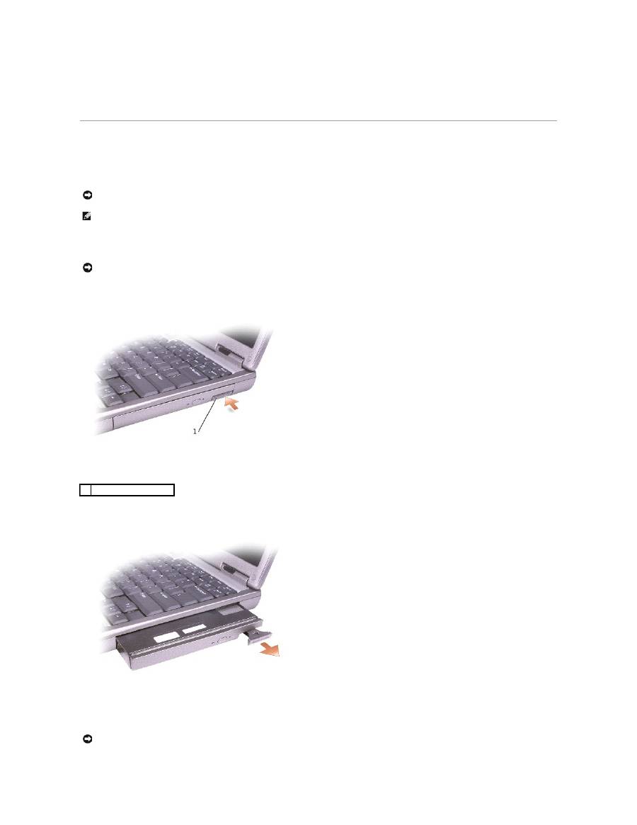
Devices
Your computer ships with an optical drive installed in the module bay. However, the device security screw is not installed in the optical drive but packaged
separately. When you install your device in the module bay, you can install the device security screw.
If the Device Security Screw Is Not Installed
1.
Press the device latch release so that the latch release pops out.
2.
Pull the device by the latch release to remove the device from the module bay.
If the Device Security Screw Is Installed
1.
If the computer is connected to a docking device (docked), undock it. See the documentation that came with your docking device for instructions.
NOTICE:
Insert devices into the module bay before you dock and turn on the computer.
NOTE:
You do not need to install the device security screw unless you want to secure the module inside the computer for security purposes.
NOTICE:
To prevent damage to devices, place them in a safe, dry place when they are not installed in the computer. Avoid pressing down on them or
placing heavy objects on top of them.
1 device latch release
NOTICE:
To prevent damage to devices, place them in a safe, dry place when they are not installed in the computer. Avoid pressing down on them or
placing heavy objects on top of them.
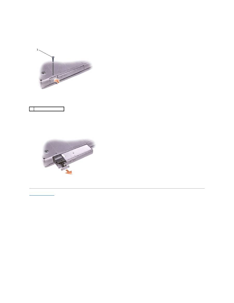
2.
Close the display and turn the computer over.
3.
Use a #1 Phillips screwdriver to remove the M2 x 3-mm screw from the bottom of the computer.
4.
Press the device latch release so that the latch release pops out.
5.
Pull the device by the latch release to remove the device from the module bay.
Back to Contents Page
1
M2 x 3-mm screw
- 1
- 2
